
Related Manuals for Thermal Dynamics PAKMaster 100 XL Plus


Summary of Contents for Thermal Dynamics PAKMaster 100 XL Plus
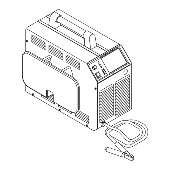
- Page 1 Plasma Cutting Power Supply ® PAKMaster 100 XL Plus A-02464 Operating Manual February 10, 2003 Manual No. 0-2748...
- Page 3 Manufacturer assumes no liability for its use. Plasma Cutting Power Supply PAK Master ® 100XL Plus Operating Manual Number 0-2748 Published by: Thermal Dynamics Corporation 82 Benning Street West Lebanon, New Hampshire, USA 03784 (603) 298-5711 www.thermal-dynamics.com Copyright 1999 by Thermal Dynamics Corporation All rights reserved.
-
Page 4: Table Of Contents
TABLE OF CONTENTS SECTION 1: GENERAL INFORMATION ....................1-1 1.01 Notes, Cautions and Warnings ..............1-1 1.02 Important Safety Precautions ............... 1-1 1.03 Publications ....................1-2 1.04 Note, Attention et Avertissement ..............1-3 1.05 Precautions De Securite Importantes ............1-3 1.06 Documents De Reference ................ - Page 5 TABLE OF CONTENTS (continued) SECTION 5: SERVICE ......................... 5-1 5.01 Introduction ....................5-1 5.02 General Maintenance ................... 5-1 5.03 Common Operating Problems ..............5-2 5.04 Troubleshooting Guide ................. 5-4 5.05 Power Supply Parts Replacement ..............5-6 SECTION 6: PARTS LISTS ........................6-1 6.01 Introduction ....................
-
Page 7: General Information
SECTION 1: GASES AND FUMES GENERAL INFORMATION Gases and fumes produced during the plasma cutting process can be dangerous and hazardous to your health. 1.01 Notes, Cautions and Warnings • Keep all fumes and gases from the breathing area. Throughout this manual, notes, cautions, and warnings Keep your head out of the welding fume plume. -
Page 8: Publications
• Wear dry gloves and clothing. Insulate yourself from the work piece or other parts of the welding PLASMA ARC RAYS circuit. • Repair or replace all worn or damaged parts. Plasma Arc Rays can injure your eyes and burn your skin. •... - Page 9 6. ANSI Standard Z49.2, FIRE PREVENTION IN THE USE OF CUTTING AND WELDING PROCESSES, obtain- able from American National Standards Institute, 1430 Broadway, New York, NY 10018 7. AWS Standard A6.0, WELDING AND CUTTING CON- TAINERS WHICH HAVE HELD COMBUSTIBLES, ob- tainable from American Welding Society, 550 N.W.
-
Page 10: Declaration Of Conformity
Rigorous testing is incorporated into the manufacturing process to ensure the manufactured product meets or exceeds all design specifications. Thermal Dynamics has been manufacturing products for more than 30 years, and will continue to achieve excellence in our area of manufacture. -
Page 11: Statement Of Warranty
None Warranty repairs or replacement claims under this limited warranty must be submitted by an authorized Thermal Dynamics® repair facility within thirty (30) days of the repair. No transportation costs of any kind will be paid under this warranty. Transportation charges to send products to an authorized warranty repair facility shall be the responsibility of the customer. - Page 12 GENERAL INFORMATION May 14, 2002...
-
Page 13: Introduction
The PCH / M-102 torch provides a maximum 1 inch (25.4 SECTION 2: mm) cut capacity. Hand torches are available in a 70° INTRODUCTION and 90° configuration; a machine torch is available in a 180° configuration. Torch leads are available in 25 ft (7.6 m), or 50 ft (15.2 m) lengths with fittings for simple in- stallation. -
Page 14: Power Supply Options And Accessories
7. Cut Capacity (Mild Steel) C. High Pressure Regulators 1 inch (25.4 mm); 1-1/4 inch (31.8 mm) severance High pressure regulators are available for air and ni- trogen. The regulators are used to set the proper pres- 8. Pilot Circuitry sure for the type gas being used. -
Page 15: Installation
SECTION 3: 3.03 Unpacking INSTALLATION Each component of the system is packaged and protected with a carton and packing material to prevent damage during shipping. 3.01 Introduction 1. Unpack each item and remove any packing material. The Cutting Spare Parts Kit is shipped in the Torch This section describes installation of the Power Supply Leads Storage Area on the side of the Power Supply. -
Page 16: Input Power Connections
1. Remove the screws which secure the left side panel 3.05 Input Power Connections (viewed from front of unit) to the frame assembly. The Power Supply accepts input voltages from 208V to 460V. Input can be 50 or 60 Hz, single-phase or three- Left Side phase. -
Page 17: Primary Input Power Cable Connections
To change the voltage selection use the following proce- 3.07 Primary Input Power Cable dure as required: Connections 1. Pull the single wire voltage selection plug from the Units ordered as 230V, single-phase, have a six foot power connector mounted on the internal center chassis. input cable and plug factory installed. -
Page 18: Gas Connections
c. Locate the ground stud and remove the top nut and washer. Input d. Install a lug terminal on the ground wire. Contactor e. Place the ground wire terminal onto the ground stud and secure with the nut and washer. f. - Page 19 B. Checking Air Quality D. Optional Air Line Filter Installation To test the quality of air, place the RUN / SET / LATCH Filtering is required when using air from a compressor to switch to SET position, place a welding filter lens in front ensure that moisture and debris from the supply hose does of the torch and turn on the gas.
-
Page 20: Connecting Torch Leads
E. Using High Pressure Gas Cylinders The Torch Leads must be properly installed to the Power Supply for proper operation. If the torch leads were not 1. Refer to the following when using high pressure gas factory-installed, make all torch connections to the Torch cylinders as the gas supply: Bulkhead Panel for the desired application. - Page 21 10. Tighten the Strain Relief onto the Torch Leads. Strain Relief 11. Check the torch for proper parts assembly. Torch Leads 12. Close the access panel and turn the latching screw. Assembly B. Machine Systems (Unshielded Leads) WARNING Strain Relief Negative / Disconnect primary power at the source before as- Plasma Lead...
- Page 22 6. Connect the Control Circuit Connectors to the mating connectors on the Adapter supplied on the Power Supply (see Warning). Adapter Connector Negative/Plasma Lead Connection Power Supply Adapter WARNING Control Circuit Connectors The Adapter supplied with the Power Supply has Open two additional Shield Connectors that are used for Shielded Systems only.
- Page 23 C. Machine Systems (Shielded Leads) Adapter Connector WARNING Negative/Plasma Adapter Lead Connection (Supplied With Power Supply) Disconnect primary power at the source before as- sembling or disassembling the power supply, torch Control (PIP) Circuit Connectors parts, or torch and leads assemblies. Shield Connectors 1.
-
Page 24: Ground Connections For Mechanized Applications
6 - 8 ft (1.8 - 2.4 m) into the earth so that For Thermal Dynamics components it is recom- the rod contacts moist soil over most of its length. mended to use a minimum of 10 AWG (European 6... -
Page 25: Tip Saver / Drag Cut Sensing Circuit
3.11 Tip Saver / Drag Cut Sensing Circuit 115VAC: 3.0 VAC This power supply is equipped with a Tip Saver / Drag 230VAC: 1.5 VAC Cut Sensing Circuit which cuts current back to 35 amps if the tip touches the workpiece. The purpose of this is to prolong the life of the tip. - Page 26 INSTALLATION 3-12 Manual 0-2748...
-
Page 27: Operation
B. Control Panel Components SECTION 4: OPERATION 4.01 Operating Controls CURRENT This subsection provides specific functional descriptions TEMP of the Power Supply operating controls and indicators. A. Front and Side Panel Components 1. Control Panel All operator controls, except gas pressure adjustment, are located on this panel. - Page 28 3. RUN / SET / LATCH Switch C. Torch Bulkhead Panel RUN (up) position is used for general torch operation The torch bulkhead panel is under the access panel. (torch switch must be held). SET (center) position used 1. Pilot Lead Stud for setting pressure and purging gas lines.
- Page 29 D. Rear Panel Components 4. Optional Filters Single-Stage Air Filter Assembly 1. Gas Input This in-line filter removes moisture and contaminants Input connection for air or nitrogen (N2) input. from the air stream when using compressed air. The filter is capable of filtering to at least 0.85 microns. WARNING This unit not to be used with oxygen (O A-02460...
-
Page 30: Sequence Of Operation
5. Place RUN / SET / LATCH switch to RUN mode. a. Gas flow stops. b. GAS indicator turns OFF. 6. Protect eyes and press or activate torch switch a. Gas pre-flows starts. b. GAS indicator turns ON. 7. After gas pre-flow (approximately 2 seconds) a. -
Page 31: Preparations For Operating
13. Gas will flow for 20 seconds (post-flow). a. Gas solenoid closes Make a solid work cable connection to the work- b. Gas flow stops. piece or cutting table c. GAS indicator turns OFF. 14. Place the ON / OFF power switch on the front panel of the unit to OFF a. -
Page 32: Cut Quality
Cut quality will vary on different types of material and 4.04 Cut Quality thicknesses. Cut quality requirements differ depending on applica- The following table shows the cut quality that can be ex- tion. For instance, nitride build-up and bevel angle may pected from this equipment for materials with a thick- be major factors when the surface will be welded after ness from gage to 1 inch (25.4 mm):... -
Page 33: Service
5. The filter element and spool, with the baffle ring SECTION 5: in place (teeth facing downward) can be screwed SERVICE back into the Regulator body by compressing the spring on the spool. Tighten firmly by hand. 5.01 Introduction This section describes basic maintenance procedures per- Regulator/Filter formable by operating personnel. -
Page 34: Common Operating Problems
WARNING Housing Always turn off the air supply and bleed the sys- tem before disassembling the Filter Assembly as injury could result. Filter Element 3. Loosen the two bolts on the top of the Filter As- (Cat. No. 9-7741) sembly enough to allow the Filter Elements to move freely. - Page 35 Cutting current too low D. Direction of Cut f. Non - genuine Thermal Dynamics parts used In the torches, the plasma gas stream swirls as it leaves 2. Main Arc Extinguishes the torch to maintain a smooth column of gas.
-
Page 36: Troubleshooting Guide
Close main power panel switch. e. Improperly assembled torch 2. Input power not properly connected to customer's main f. Non - genuine Thermal Dynamics parts used power panel 5.04 Troubleshooting Guide a. Check that input power is present and unit is properly connected (refer to Section 3.05, In-... - Page 37 5. Faulty components in unit 2. Incorrect setting of CURRENT control a. Return for repair or have qualified technician a. Check and adjusted to proper setting. repair per Service Manual. 3. Faulty components in unit C. Torch will not pilot when torch switch is activated a.
-
Page 38: Power Supply Parts Replacement
B. Fuse Replacement 5.05 Power Supply Parts Replacement 1. Remove the left side panel per paragraph "A" above. 2. Locate the internal fuse on the left side of the unit. WARNING 3. Replace the fuse. See Section 6, Parts Lists, for re- placement fuse catalog number. -
Page 39: Parts Lists
SECTION 6: PARTS LISTS 6.01 Introduction Parts List Breakdown The parts list provide a breakdown of all replaceable com- ponents. The parts lists are arranged as follows: Section 6.03 Complete Power Supply Replacement Section 6.04 Replacement Parts Section 6.05 Options and Accessories NOTE Parts listed without item numbers are not shown, but may be ordered by the catalog number shown. -
Page 40: Complete Power Supply Replacement
6.03 Complete Power Supply Replacement Power supply includes: Work cable and clamp, pressure regulator/air filter, and operating manual. Description Catalog # PAK Master 100XL PLUS Power Supply 208/230 VAC, Single - Phase, with Input Cable and Molded Plug 3-0056-1 460 VAC, Three - Phase, without Input Cable and Plug 3-0056-2 6.04 Replacement Parts Description... -
Page 41: Appendix 1: Input Wiring Requirements
APPENDIX 1: INPUT WIRING REQUIREMENTS Input Power Input Current Input Suggested Sizes (See Notes) Voltage Freq. 1-Ph 3-Ph 1-Ph 3-Ph Fuse (Amps) Wire (AWG) Wire (Canada) (Volts) (Hz) (kVA) (kVA) (Amps) (Amps) 1-Ph 3-Ph 1-Ph 3-Ph 1-Ph 3-Ph 50/60 18.9 17.3 50/60 18.9... -
Page 42: Appendix 2: Sequence Of Operation (Block Diagram
APPENDIX 2: SEQUENCE OF OPERATION (BLOCK DIAGRAM) LATCH ACTION ACTION ACTION ACTION ON/OFF switch Close external RUN/SET/LATCH RUN/SET/LATCH switch to ON. disconnect switch. switch to RUN. to SET. RESULT RESULT RESULT RESULT AC indicator blinks for 8 Power to system. Gas flow stops. -
Page 43: Appendix 3: Maintenance Schedule
APPENDIX 3: MAINTENANCE SCHEDULE This schedule applies to all types of non - liquid cooled plasma cutting systems. Some systems will not have all the parts listed and those checks need not be performed. NOTE The actual frequency of maintenance may need to be adjusted according to the operating environment. Daily Operational Checks or Every Six Cutting Hours: 1. -
Page 44: Appendix 4: System Schematic
APPENDIX 4: SYSTEM SCHEMATIC INRUSH INRUSH A-02465 APPENDIX Manual 0-2748... - Page 45 OK TO MOVE 8/23/99 08/23 AC EC 8397 A-02465 Manual 0-2748 APPENDIX...
Need help?
Do you have a question about the PAKMaster 100 XL Plus and is the answer not in the manual?
Questions and answers