Table of Contents
Advertisement
374RAN
MULTIPOISE OIL FURNACE
FOR INPUT CAPACITIES OF 70,000- -154,000, SERIES B
NOTE: Read the entire instruction manual before starting the
installation.
TABLE OF CONTENTS
. . . . . . . . . . . . . . . . . . . . . . . . . . . . . . . . . . .
. . . . . . . . . . . . . . . . . . . . . . . . . . . . . . . . . . . . . . . .
. . . . . . . . . . . . . . . . . . . . . . . . . . . . . . . . . . .
. . . . . . . . . . . . . . . . . . . . . . . . . . . . . . . . . . . .
. . . . . . . . . . . . . . . . . . . . . . . . . . . . . . . . . . .
. . . . . . . . . . . . . . . . . . . . . . . . . . . . . . . . . . .
. . . . . . . . . . . . . . . . . . . . . . . . . . . . . . . .
. . . . . . . . . . . . . . . . . . . . . . . . . . . .
. . . . . . . . . . . . . . . . . . . . . . . . . . . . . . . . . . . . . . . . . .
. . . . . . . . . . . . . . . . . . . . . . . . . . . . . . . . . .
. . . . . . . . . . . . . . . . . . . . . . . . . . . . . . .
Installation Instructions
. . . . . . . . . . . . . . . . . . . . . . . . .
. . . . . . . . .
. . . . . . . . . . . . .
. . . . . . . . . . . . . . . . . .
. . . . . . . . . . . . . . . . . . . . .
. . . . . . . . . . . . . . . . . . . . .
. . . . . . . . . . . . . . . . . . . . .
. . . . . . . . . .
. . . . . . . . . . . . . . . . . . . . . .
. . . . . . . . . . . . . . . . . . . . . .
. . . . . . . . . . . . . . . . . . . . . . . . .
. . . . . . . . . . . . . . . . . . . . . .
. . . . . . . . . . . . . . . . . . . . . . .
. . . . . . . . . . . . .
. . . . . . . . . . . . . . . . . . . . . . . .
. . . . . . . . . . . . . . . .
. . . . . . . . . . . . . . . . . . . . . . . . . .
PAGE
1
3
3
3
4
4
4
4
5
8
8
9
9
9
9
11
13
.
13
13
13
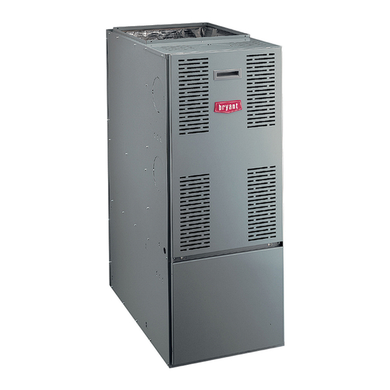
Fig. 1 - - 374RAN Multipoise Oil Furnace
15
SAFETY CONSIDERATIONS
16
17
Recognize safety information. This is the safety- -alert symbol
When you see this symbol on the furnace and in instructions or
17
manuals, be alert to the potential for personal injury.
17
Understand the signal words DANGER, WARNING, and
17
CAUTION. These words are used with the safety- -alert symbol.
DANGER identifies the most serious hazards which will result in
17
severe personal injury or death. WARNING signifies a hazard
18
which could result in personal injury or death. CAUTION is used
18
to identify unsafe practices which may result in minor personal
injury or product and property damage. NOTE is used to highlight
suggestions which will result in enhanced installation, reliability, or
operation.
ama
B140.0--- B140.4--- UL727
A06623
.
157971
Advertisement
Table of Contents

Related Manuals for Bryant 374RAN


Summary of Contents for Bryant 374RAN
-
Page 1: Table Of Contents
Step 2 — Sequence of Operation ..... . Fig. 1 - - 374RAN Multipoise Oil Furnace Step 3 — Combustion Check . - Page 2 TOP KNOCK-OUT FOR J DIAM VENT 20 in. (51 mm) (483 mm) 3 in. (76 mm) KNOCK-OUT BOTH SIDES 19 in. FOR J DIAM VENT (483 mm) PULL VENT CONN OIL INLET (BOTH SIDES) 2 in. (51 mm) ELECTRICAL CONNECTIONS (BOTH SIDES) .88 DIAM TYP 20 in.
-
Page 3: Introduction
INTRODUCTION - -Clean outside air is provided for combustion. This is to The model 374RAN Furnace is available in two sizes. Each size minimize the corrosive effects of adhesives, sealers and other unit is capable of 3 heat/airflow combinations by a simple nozzle construction materials. -
Page 4: Step 2 - Location Relative To Cooling Equipment
Table 1 – Minimum Clearances to Combustible Materials - - In. (mm) UNIT APPLICATION UPFLOW DOWNFLOW HORIZONTAL Furnace 0 (0) 2 (51) 2 (51) Sides Supply Plenum and Warm--- Air Duct Within 6 ft. (1.8 M) of 1 (25) 2 (51) 1 (25) Furnace Back... -
Page 5: Step 3 - Ductwork Recommendations
space, the number of windows and ventilation openings, the 2. If combustion air is taken from outdoors through vertical number of doors to the outside, internal doors which can close off ducts, the openings and ducts MUST have at least 1 in. unconfined space, and overall tightness of building construction. - Page 6 NOTE: Both acoustical lining and fibrous ductwork shall comply with NFPA 90B as tested by UL Standard 181 for Class 1 Rigid air Ducts. Chimney Ventilation louvers (each end of attic) Outlet air Furnace Water heater Inlet air duct [ends 1 ft (0.3m) above floor] The Outlet air duct and Inlet air duct must have free area of not less than 1 square inch per 4000 BTUH based on the total input rating of all appliances in the space.
- Page 7 Chimney Outlet air duct Furnace Water heater Inlet air duct The Outlet air duct and Inlet air duct must have a free area of not less than 1 square inch per 2000 BTUH based on the total input rating of all appliances in the space. A06465 Fig.
-
Page 8: Step 4 - Venting
Step 4 — Venting 3. Cleaning chimney or vent if previously used for venting a solid fuel burning appliance or fireplace. Venting of furnace should be to the outside and in accordance with 4. Confirming that all unused chimney or vent connections are local codes or requirements of local utility. -
Page 9: Step 6 - Oil Burner
Step 6 — Oil Burner WARNING This furnace is supplied with a high- -pressure atomizing retention head- -type burner (for use with grade 1 or 2 Fuel Oil). The FIRE, CARBON MONOXIDE POISONING HAZARD mounting flange is fixed to burner air tube and no adjustment is required for insertion length. - Page 10 The Blocked Vent Shut-Off The BVSO must be (BVSO) must be installed installed between 2 in. between the furnace outlet and 12 in. from the and the draft regulator. furnace outlet. Use the three wire fastners. The wires must not come in contact with the flue and cleaning pipes.
-
Page 11: Step 10 - Electrical Connections
Step 10 — Electrical Connections WARNING ELECTRICAL SHOCK HAZARD Failure to follow this warning could result in personal injury or death. The unit cabinet must have an uninterrupted or unbroken electrical ground. A green ground screw is provided in control box for this connection. 115- -V Wiring Before proceeding with electrical connections, make certain that voltage, frequency, and phase correspond to that specified on unit... -
Page 13: Step 11 - Horizontal Or Downflow Installation
Accessory Installation Table 4 – Filter Size and Quantity 1. General UNIT AIR FILTER SIZE FLANGE OPENING SIZE When installing optional accessories to this appliance, SIZE IN (mm) IN (mm) follow manufacturer’s Installation Instructions included 16 x 24 x 1 with accessory. - Page 14 A04183 A04185 Fig. 15 - - 24- -VAC Oil Furnace Wiring with 1- -Speed Fig. 17 - - 24- -VAC Oil Furnace with 1- -Speed Air Conditioner Heat Pump A04184 A04186 Fig. 16 - - 24- -VAC Oil Furnace Wiring with 2- -Speed Fig.
-
Page 15: Step 3 - Combustion Check
Oil Fired Heating Mode low- -cooling airflow. When the thermostat is satisfied, the BLWM switches to continuous- -blower airflow. 1. The thermostat closes R to W. 4. When the thermostat calls for high cooling, the BLWM 2. Burner motor starts. The burner motor fan pre- -purges the keeps continuous- -blower speed until the end of “Short run”... -
Page 16: Step 4 - Fan Adjustment Check
1. On a new installation, air entrapped in oil line leading from Table 5 – Furnace Draft Conditions (in wc) tank to nozzle must be thoroughly purged in order to TOTAL prevent excessive after drip. The oil pump is provided with FURNACE FLUE DRAFT OVER--- FIRE DRAFT... -
Page 17: Step 5 - Limit- -Control Check
Table 7 – 374RAN105 Dip Switch Adjustment for Oil Heating WARNING Mode SW1--- HEAT DIP SWITCH SW4--- DELAY DIP INPUT INPUT FIRE HAZARD AND UNIT RELIABILITY POSITION SWITCH POSITION USGPH USGPH Failure to follow this warning could result in property 0.75 0.75 damage, personal injury, or death. -
Page 18: Step 3 - Heat Exchanger And Flue Pipe
Depending on above inspection, service could also include a 1. Turn off all oil and electrical supplies upstream of furnace. cleaning and vacuuming of heat exchanger tubes and possibly the 2. Disconnect flue pipe. heat exchanger drum section. 3. Remove flue collar panel located in front part of furnace. Removal of any heat exchanger components which are sealed by 4. - Page 19 120 VAC NEUTRALS 120 VAC HEAT COOL OFF OFF OFF OFF ON ON ON ON DELAY OFF OFF OFF OFF ON ON ON ON LED7 LED4 LED3 LED5 LED7 LED8 LED1 Y/Y2 NOTES 1. The Red LED to the right of P-1 will illuminate whenever the limit switch is open. 2.
- Page 20 Table 13 – 374RAN105 OIL HEATING MODE 24 VAC INPUT (R) ON W ONLY AIRFLOW (CFM) SW1--- HEAT HEAT INPUT EXTERNAL STATIC PRESSURE (IN WC) DIP SWITCH POSITION (USGPH) A (1=OFF, 2=OFF)* 1128 1146 1146 A (1=OFF, 2=OFF)** 0.75 1275 1295 1295 A (1=OFF, 2=OFF)***...
- Page 21 Table 13 - - 374RAN120 (cont) OIL HEATING MODE 24 VAC INPUT (R) ON W ONLY AIRFLOW (CFM) SW1--- HEAT HEAT INPUT EXTERNAL STATIC PRESSURE (IN WC) DIP SWITCH POSITION (USGPH) A (1=OFF, 2=OFF)* 1417 1417 1417 1407 A (1=OFF, 2=OFF)** 1601 1601 1601...
- Page 22 Catalog No. II374R ---105--- 5 E2009 Bryant Heating & Cooling Systems 7310 W. Morris St. Indianapolis, IN 46231 Printed in U.S.A. Edition Date: 05/09 Manufacturer reserves the right to discontinue, or change at any time, specifications or designs without notice and without incurring obligations.
Need help?
Do you have a question about the 374RAN and is the answer not in the manual?
Questions and answers