DriSteem VAPOR-LOGIC 3 Installation And Operation Manual
Microprocessor-based humidifier control system
Hide thumbs
Also See for VAPOR-LOGIC 3:
- Field conversion instructions (4 pages) ,
- Conversion instructions (4 pages) ,
- Installation manual (22 pages)

Related Manuals for DriSteem VAPOR-LOGIC 3


Summary of Contents for DriSteem VAPOR-LOGIC 3
- Page 1 Read and save these instructions! VAPOR-LOGIC ® Microprocessor-based humidifier control system Installation and operation manual...
- Page 2 Corporate headquarters European office 14949 Technology Drive • Eden Prairie, MN 55344 Bell Place, Bell Lane • Syresham, Brackley • NNN13 5HP, UK 952-949-2415 • 800-328-4447 • 952-949-2944 (fax) +44 1280 850122 • +44 1280 850124 (fax) sales@dristeem.com (e-mail) 106277.1443@compuserv.com (e-mail)
- Page 3 Product overview VAPOR-LOGIC features overview. ® Accurate, responsive Control mode options microprocessor control • On-off operating mode controls single or Our newest controller, VAPOR-LOGIC multiple electric staged outputs. provides unprecedented, comprehensive control for Expected accuracies: ±5-7% RH DRI-STEEM humidifiers. With expanded capabilities, easy-to-use keypad, and modular, open •...
- Page 4 Product overview VAPOR-LOGIC features overview. ® Summary of features • Tank temperature sensor: • PID control provides the most accurate, – preheats tanks for uninterrupted operation responsive and adjustable relative humidity – senses for freeze protection (RH) control. – senses for low water/over temperature •...
- Page 5 Product overview VAPOR-LOGIC circuit board. ® Figure 3-1: VAPOR-LOGIC printed circuit board Ready Power water indicator RJ-11 indicator 5/64" dia. Cable RJ-45 (6) mounting holes keypad Service Cable indicator network To expansion board (ribbon cable) 4.228 3.548 Jumper connector 0.339 R=Resistive input I=Current input V=Voltage input...
-
Page 6: Main Control Board Connections
Product overview Main control board connections. ® VAPOR-LOGIC main control board connections J1 Wire terminal supplies 24 VAC to power the J8 Connector receives necessary continuity input VAPOR-LOGIC control board. signals from water detection devices: • Double terminal T1 – 24 VAC, 10 VA •... - Page 7 Product overview Main control board connections (cont.). Main control board connections (cont.) Important note about J17, J18 and J19: J18 Identical to J17 input selector pins except used to configure duct high limit RH input (terminals All connection diagrams show connector shunts 24 through 26) for wire connector terminal J27 on J17, J18 and J19.
- Page 8 Product overview Main control board connections (cont.). Main control board connections (cont.) J23 Wire terminal connection provides optically J27 Wire terminal connector receives the necessary isolated connection to air flow proving switch signal from the duct high limit RH sensor. and safety circuit.
- Page 9 Product overview Expansion board connections. ® ® and VAPORSTREAM expansion board connections J8 Wire terminal connector supplies 24 VAC voltage with terminal pairs 1 and 2, 3 and 4, and 5 and 6 J1 1/4" push-on connector for earth ground to either contactors or GTS ignition controllers.
- Page 10 Product overview Program code nomenclature. F. System pounds output: Program code explained ##### = Output capacity ® A 14-digit VAPOR-LOGIC program code appears on (e.g., 00285 = output capacity in lbs/hr) the front of the control cabinet and on the wiring G.
- Page 11 Product overview Program code nomenclature. Program code example 00048 A. English ® B. VAPORMIST C. One-tank system D. Single keypad One heat stage 48 lbs/hr capacity G .. Standard water with autodrain H.. TP operating mode No VAV option No temp comp option K.
-
Page 12: Two-Year Limited Warranty
Product overview Two-year limited warranty. DRI-STEEM Humidifier Company (“DRI-STEEM”) DRI-STEEM’s limited warranty is made in lieu of, warrants to the original user that its products will be and DRI-STEEM disclaims all other warranties, free from defects in materials and workmanship for a whether express or implied, including but not limited period of two (2) years after installation or twenty- to any IMPLIED WARRANTY OF... -
Page 13: Installation Checklist
Installation Installation checklist. ® Before installing your VAPOR-LOGIC control Attach the heater/machine ground lug in the system, review this checklist to ensure proper junction box, on the humidifier, to the subpanel installation of the product. Failure to follow the machine ground lug with the appropriate wire, recommendations listed below could result in failure sized per equipment grounding section of The or damage to the humidifier or microprocessor. -
Page 14: Proper Wiring Procedures
Installation Proper wiring procedures. Proper wiring prevents electrical noise Most noise problems can be prevented by using proper wiring practices and techniques to prevent Electrical noise can produce undesirable effects on coupling or inducing of electrical interference into electronic control circuits, thereby affecting control circuits. - Page 15 Installation Proper wiring procedures (cont.). Proper wiring prevents electrical noise (cont.) • Return all shielded cable connections to the control cabinet for grounding. Do not ground • Do not use chassis or safety grounds as current- shield at the device end. carrying commons.
- Page 16 Installation Control cabinet installation and wiring. ® The VAPOR-LOGIC control board is shipped • VAPOR-LOGIC is powered by a low voltage mounted with all internal wiring completed within a Class 2 control transformer. The transformer control cabinet. All software has been custom provides a 24 VAC supply, and is protected by programmed into your VAPOR-LOGIC system...
- Page 17 Installation Keypad/display installation. Installing modular cable Installing the keypad/display IMPORTANT: When routing modular cable IMPORTANT: Do not locate the keypad/display inside the control cabinet, route cable away from all inside the control cabinet. The hardware is power wiring and connect the male modular plug into premounted in the keypad/display case with front ®...
- Page 18 Installation Sensing devices and humidity control. Important to properly place sensing devices Other factors that affect humidity control Humidity sensing devices must be properly placed to Unsatisfactory humidity control may involve more achieve accurate humidity control. A typical small air than just the controller’s capability to control the handling system is shown in the drawings on Pages system.
-
Page 19: System Diagram
Installation System Diagram. Figure 17-1: System diagram Line voltage ® ULTRA-SORB Liquid level detectors dispersion unit Electrical supply Keypad/display 24 volt Line voltage Control cabinet VAPORSTREAM ® VLC humidifier OM-3007 Installation: Component placement... - Page 20 Installation Placement of sensing devices. Figure 18-1: Recommended sensor locations Best Alternative location Not recommended Best duct high limit humidistat High limit humidistat or high limit transmitter (set at 90% RH max.) placement for VAV 10' min. Outside air applications (3 meters) Air flow switch (sail type...
- Page 21 Installation Wiring of sensing devices. Wiring on-off humidistats Wiring modulating humidity or temperature transmitters DRI-STEEM provides three types of on-off controls: wall-mounted humidistat, duct-mounted humidistat, Transmitters provide an analog signal proportional to or pneumatic/electric relay. The wiring diagram the process variable being measured. All transmitters (found on the inside of the humidifier control provided by DRI-STEEM are two-wire devices.
- Page 22 Installation Wiring of sensing devices. Figure 20-1: Example of proper shielding techniques when ® connecting humidity or temperature devices to VAPOR-LOGIC control inputs OM-VL3-17 Note: The wiring diagram (found on the inside of the humidifier control cabinet) will show the proper controls wiring.
- Page 23 Installation Wiring VAV sensing device. Variable air volume (VAV) option When this occurs, the keypad/display will show the message “VAV output limit.” If necessary, the This option is identified as a “V” in the third-from-last reduction of the humidifier output will continue until place of your program code nomenclature (for maximum high limit set point has been reached, example: EV11400285A7VOX).
- Page 24 Installation Temperature compensation transmitter. Temperature compensation offset option The transmitter provided with VAPOR-LOGIC calibrated for -20°F to 160°F (-29°C to 71°C) with This option is identified as a “T” in the second-from- output from 4-20 mA. For example, a temperature last place of your program code nomenclature (for reading of 70°F should produce a measurement of example: EV11400285A7OTX).
- Page 25 Installation Changing control input. Changing control input Change the last character in the configuration string to the desired input signal type identified ® VAPOR-LOGIC has the ability to accept different from the program coded nomenclature types of demand signals from either an energy information on Pages 8 and 9.
-
Page 26: Start-Up Checklist
Operation Start-up checklist. Note: Check the integral gain setting in the Your humidification system may not have all “System Set Up” menu of the keypad/display of the options listed below. If an item does not (default is 40). appear, skip to the next item and continue the Check the derivative gain setting in the process. - Page 27 Operation Start-up checklist (cont.). Confirm that all wiring is correct per the wiring Confirm that the high limit humidistat input is diagram. closed or that the variable air volume (VAV) control system high limit transmitter is Confirm that proper grounding and an approved connected.
-
Page 28: Keypad/Display Overview
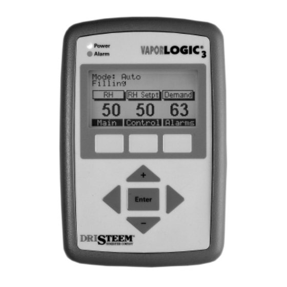
Operation Keypad/display overview. Components of the keypad/display The menu system ® The VAPOR-LOGIC keypad/display consists of The VAPOR-LOGIC keypad/display software (see Figure 26-1 below): organizes the control of the humidification system under six top-level screens: • A 128 x 64-pixel backlit LCD display •... - Page 29 Operation VAPOR-LOGIC menu structure. ® Main Menu 1) Status Soft key) Main – Returns to the Main Menu screen Soft key) Back – Scrolls to the previous Status item Soft key) Next – Scrolls to the next Status item 2) Control Modes 1) Auto Mode 2) Test Mode 3) Manual Drain...
- Page 30 Operation “Set Up” menu information. “Set Up” menu “Set Up” menu Range Default readout description RH Set point Relative humidity set point 20-80% RH RH Offset RH offset calibration ±20% RH Dewpoint Set point Dew point set point 20-80°F/-7-27°C 50°F/10°C Dewpoint Offset Dew point offset calibration ±20°F/±20°C...
- Page 31 Operation Keypad/display readouts. Readout displayed Description Filling The unit is filling with water. Skimming The unit has completed a fill cycle and is now skimming. Draining The unit is draining. Flushing The unit is flushing. No Duct Air Flow The air flow proving switch is open. Interlock Disable The interlock circuit is open.
- Page 32 Operation Main menu: 1) Status. Status The Status screen is used to view some of the operating parameters of the humidification system. Some of the parameters that may be displayed include: • RH setpoint • Room RH • Dewpoint setpoint •...
- Page 33 Operation Main menu: 2) Control Modes. Control Modes In the Control Modes screen, the operational mode of the humidifier can be set. You may choose from auto, test, manual drain or standby. In Auto Mode, the humidifier operates normally. All inputs and outputs are monitored and controlled.
- Page 34 Operation Main menu: 3) Alarms. Alarms The Alarms screen is used to view the alarm log. Use the vertical arrow keys to scroll through the alarm log. The alarm log contains a record of the previous 10 faults that have occurred on the humidifier. The alarms may either be acknowledged or cleared using the soft keys below the display.
- Page 35 Operation Main menu: 4) Set Up. Set Up In the Set Up screen, the operational parameters of the humidifier can be set. Depending on system options, parameters available may include: • RH setpoint • RH offset • Dewpoint setpoint • Dewpoint offset •...
- Page 36 Operation Main menu: 5) Diagnostics. Depending on system options and type, diagnostics Diagnostics available may include: The Diagnostics screen enables you to troubleshoot • RH input some of the hardware input and output points of the ® VAPOR-LOGIC control system. The soft keys Next •...
- Page 37 Operation Main menu: 6) Reports. Reports The Reports screen is useful for viewing historical information about your humidifier. In this section, you are able to view the amount of water that has been used by your humidifier and the amount of energy it has consumed.
- Page 38 Operation Main menu: Idle screen. Idle Screen The Idle screen allows you to monitor the humidifier’s basic operation. Depending on system options, you may view system set point, the actual space condition and the system demand. The top line of the display informs you of the current mode of the humidifier.
-
Page 39: Control Modes
Operation Control modes. On-off control Demand signal control Transmitter control Operation: Control modes... - Page 40 Operation Modulation types: TP modulation. TP modulation Operation: TP modulation...
- Page 41 Operation Modulation types: SSR modulation. 100% SSR modulation SSR modulation with contactors Operation: SSR modulation...
- Page 42 Operation Modulation types: valves and burners. ® ® ® , LTS and ULTRA-FOG valve modulation ® burner modulation Operation: Valve and burner modulation...
- Page 43 Operation Control functions: adjusting set point. Adjust set point through Set Up menu Operation: Adjusting set point...
- Page 44 Operation Control functions: PID tuning. Tune your system with PID loop The proportional term The integral term Operation: PID tuning...
- Page 45 Operation Control functions: PID tuning (cont.). PID setup tips The derivative term Operation: PID tuning...
- Page 46 Operation VAV, temp comp, dew point control. VAV control Dew point control Temperature compensation control Operation: VAV, temp comp, dew point control...
- Page 47 Operation Aquastat, heat-up, SDU, offsets, metric. Aquastat operation SDU timer Sensor offsets Tank heat-up feature Metric conversion Operation: Aquastat, heat-up, SDU, offsets, metric...
- Page 48 Operation Water level control: conductivity probe. Probe system Figure 46-1: Conductivity probe system Figure 46-2: Conductivity probe system ® ® ® ® ® ® for GTS , VLC , VAPORMIST and CRUV for STS and LTS Water level - A Water level - B Water level - A Water level - C...
- Page 49 Operation Water level control: float valve. Float valve system Figure 47-1: Float valve system used with DI/RO systems Stem OM-3009 Operation: Float valve...
- Page 50 Operation Drain and flush, skim. Drain and flush options Skim timer Operation: Drain and flush, skim...
- Page 51 Operation Service interval, EOS, date set. Service interval Setting date and time End of season drain Operation: Service interval, EOS, date set...
-
Page 52: Safety Features
Operation Safety features. Fill timer Over-temp fault Operation: Fill timer, over-temp fault... - Page 53 Operation Fault messages, diagnostics. Alarms screen Fill and drain faults Sensor faults Operation: Fault messages, diagnostics...
- Page 54 Operation Fault messages, diagnostics (cont.). Humidifier faults Sensor meter feature Operation: Fault messages, diagnostics...
- Page 55 Operation Reports, multiple tank systems. Energy usage report Multiple tank systems Water usage report Operation: Reports, multiple tank systems...
-
Page 56: Troubleshooting
Operation Troubleshooting 1, 2, 3. Review troubleshooting index Call us if you’re still having problems Review possible causes and recommended actions Humidifier model number ___________________ Humidifier serial number ___________________ VAPOR-LOGIC program code ________________ Operation: Troubleshooting introduction... - Page 57 Operation Index to troubleshooting guide. Description Operation: Index to troubleshooting guide...
-
Page 58: Troubleshooting Guide
Operation Troubleshooting guide. Problem Problem Possible cause Action number More on next page ... Operation: Troubleshooting guide... - Page 59 Operation Troubleshooting guide. Problem Problem Possible cause Action number More on next page ... Operation: Troubleshooting guide...
- Page 60 Operation Troubleshooting guide. Problem Problem Possible cause Action number More on next page ... Operation: Troubleshooting guide...
- Page 61 Operation Troubleshooting guide. Problem Problem Possible cause Action number More on next page ... Operation: Troubleshooting guide...
- Page 62 Operation Troubleshooting guide. Problem Problem Possible cause Action number More on next page ... Operation: Troubleshooting guide...
- Page 63 Operation Troubleshooting guide. Problem Problem Possible cause Action number More on next page ... Operation: Troubleshooting guide...
- Page 64 Operation Troubleshooting guide. Problem Problem Possible cause Action number More on next page ... Operation: Troubleshooting guide...
- Page 65 Operation Troubleshooting guide. Problem Problem Possible cause Action number More on next page ... Operation: Troubleshooting guide...
- Page 66 Operation Troubleshooting guide. Problem Problem Possible cause Action number More on next page ... Operation: Troubleshooting guide...
- Page 67 Operation Troubleshooting guide. Problem Problem Possible cause Action number More on next page ... Operation: Troubleshooting guide...
- Page 68 Operation Troubleshooting guide. Problem Problem Possible cause Action number More on next page ... Operation: Troubleshooting guide...
- Page 69 Operation Troubleshooting guide. Problem Problem Possible cause Action number More on next page ... Operation: Troubleshooting guide...
- Page 70 Operation Troubleshooting guide. Problem Problem Possible cause Action number More on next page ... Operation: Troubleshooting guide...
- Page 71 Operation Troubleshooting guide. Problem Problem Possible cause Action number More on next page ... Operation: Troubleshooting guide...
- Page 72 Operation Troubleshooting guide. Problem Problem Possible cause Action number Operation: Troubleshooting guide...
- Page 75 14949 Technology Drive • Eden Prairie, MN 55344 Phone: (612) 949-2415 • Fax: (612) 949-2933 E-Mail: sales@dristeem.com • Web: www.dristeem.com European Office: Bell Place, Bell Lane • Syresham, Brackley • NN13 5HP, U.K. Phone: +44 1280 850122 • Fax: +44 1280 850124 E-Mail: 106277.1443@compuserve.com...
Need help?
Do you have a question about the VAPOR-LOGIC 3 and is the answer not in the manual?
Questions and answers