DriSteem VAPOR-LOGIC Installation And Operation Manual
Humidifier control system
Hide thumbs
Also See for VAPOR-LOGIC:
- Installation instructions & maintenance operations manual (40 pages) ,
- Installation manual (51 pages) ,
- Installation and operation manual (112 pages)

Related Manuals for DriSteem VAPOR-LOGIC


Summary of Contents for DriSteem VAPOR-LOGIC
- Page 1 READ AND SAVE THESE INSTRUCTIONS VAPOR-LOGIC ® VERSION Hum id ifi er C o nt r ol S ys te m Installation and Operation Manual...
-
Page 2: Table Of Contents
OVERVIEW Vapor-logic capabilities ........1 Humidification system overview . - Page 3 WARRANTY ............VAPOR-LOGIC VERSION 5 INSTALLATION AND OPERATION MANUAL ®...
-
Page 4: Warnings And Cautions
Failure to follow all warnings and instructions could produce the hazardous situations described here and in the IOM, resulting in property damage, personal injury, or death. If the IOM is missing, go to www.dristeem.com to download a replacement. mc_071608_0910 Hot surfaces and hot water Steam humidification systems have extremely hot surfaces, and water in tanks, electrode cylinders, steam pipes, and... -
Page 5: Overview
OVERVIEW Vapor-logic capabilities ACCURATE, RESPONSIVE CONTROL The Vapor-logic controller provides accurate, responsive RH control. PID control tunes the system for maximum performance. Modbus , BACnet , or LonTalk allow interoperability with multiple building ® ® ® automation systems. Modbus is standard, and BACnet or LonTalk are available options. - Page 6 Vapor-logic capabilities Enhanced diagnostics include: Insert a USB flash drive • Test outputs function using keypad/display or Web interface to verify into the Vapor-logic component operation board’s USB port to perform software • Test humidifier function using simulated demand to validate performance...
-
Page 7: Humidification System Overview
Web interface keypad/display Every humidification system with a Vapor-logic controller has a keypad/display connection and an Ethernet connection for connecting to a Web interface on a computer. A GTS humidifier is shown here, with keypad/display mounted on the cabinet. Other types of DriSteem humidifiers can have the keypad/display contained within a control cabinet or mounted remotely. -
Page 8: Vapor-Logic Board
BACnet or Modbus connection Connection pins for optional LonTalk module The photo above shows key components of the Vapor-logic control board. See the illustration on the next page for more detail. FIGURE 4-2: CONTROL BOARD MOUNTED ON GTS SUBPANEL Vapor-logic control board The Vapor-logic control board is mounted inside the humidifier control... - Page 9 OVERVIEW Vapor-logic board: Connections FIGURE 5-1: VAPOR-LOGIC CONTROL BOARD CONNECTIONS P19: Steam = Steam or hot water valve/XT staging/ HPS VFD = Ground for blower or steam valve SSR/BL = SSR (electric systems)/or blower (gas systems) 24vac = Power to board...
-
Page 10: Keypad/Display
OVERVIEW Keypad/display FIGURE 6-1: USING THE VAPOR-LOGIC KEYPAD/DISPLAY Typical Home screen Change set point from the Home screen by pressing the Up or Down arrow keys until set point is highlighted (as shown here), press Enter, press Up or Down arrow keys to change value, press Enter to confirm... -
Page 11: Web Interface
OVERVIEW Web interface FIGURE 7-1: USING THE VAPOR-LOGIC WEB INTERFACE (SETUP SCREEN SHOWN) Click on a tab label to move to another screen Click on CHANGE to change value To change value: Highlight value; type in new value; click on APPLY... -
Page 12: Installation
Pre-installation Checklist ☐ See Figure 8-1 for field terminal block locations. Note FIGURE 8-1: VAPOR-LOGIC CONTROL BOARD DETAIL that field wiring connection locations on the Vapor-logic Full control board board are surrounded with a white border. ☐ See the figure on the next page for instructions on how to make wiring connections. - Page 13 INSTALLATION Pre-installation Checklist FIGURE 9-1: VAPOR-LOGIC TERMINAL BLOCK DETAIL AND CONNECTION INSTRUCTIONS Tighten screw after wire is inserted. Maximum torque is Terminal block plug. 3 in-lb (0.34 N-m) Make connections when the plug is Remove insulation attached to the from end of wire...
-
Page 14: Installation Process
INSTALLATION Installation process The Vapor-logic board is designed to make installation very easy: • Terminal blocks that require field connections are outlined in white. • Terminal plugs can be removed to allow easy access when inserting wires and tightening screws. - Page 15 INSTALLATION Installation process • Communication connections – Vapor-logic keypad – Ethernet – Modbus – BACnet – LonTalk – Multiple-tank communication • Programmable triac and relay • Area-type, SDU dispersion fans, or steam blowers • Combustion air switch and power vent (GTS systems only) 2.
-
Page 16: Step 1 - Field Wiring: Control Input
21vdc = Power to space RH sensor Humidistats provide either on-off control or modulating control. DriSteem RH = Space RH input (RH transmitter, dew point humidistats are powered by a 24 VDC supply provided by the Vapor-logic transmitter, humidistat, or demand signal control board. - Page 17 INSTALLATION Step 1 – Field wiring: Control input FIGURE 13-1: VAPOR-LOGIC CONTROL INPUT WIRING CONNECTIONS Signal by others 0-10 VDC 4-20 mA Vapor-logic Vapor-logic Input resistance 21VDC 21VDC 500 ohms Control panel Control panel 2-wire #18GA 2-wire #18GA shield GND lug...
-
Page 18: Control Input Signals
INSTALLATION Step 1 – Field wiring: Control input signals DriSteem offers three control options for all its humidification systems controlled by Vapor-logic: On-off control, demand signal control, and transmitter control. ON-OFF CONTROL On-off control—the simplest control scheme—does exactly what its name implies: the output device turns fully on, then fully off. - Page 19 Calculation of transmitter % RH With modulating demand signal control, a modulating humidistat (mA reading) – 4 mA or a building automation system sends a signal to the Vapor-logic x 100% % RH = controller, which then sends a signal to the humidifier to produce 16 mA a directly proportional steam output.
-
Page 20: Limit Controls
J402 if wiring is installed. If an enable signal is not being used, jumper the MASTER ENB terminal block plug at P20 or attach the included shunt to the two pin header at J402. VAPOR-LOGIC VERSION 5 INSTALLATION AND OPERATION MANUAL ®... - Page 21 INSTALLATION Step 1 – Field wiring: Limit controls FIGURE 17-1: VAPOR-LOGIC LIMIT CONTROLS WIRING CONNECTIONS Note: An airflow switch must be used in any duct humidification application. If no airflow switch Airflow switch in a duct When using an SDU is used, install shunt at J401 (see figure 5-1).
- Page 22 Auxiliary temperature readings are logged to the data log. TEMPERATURE COMPENSATION TRANSMITTER A temperature compensation transmitter allows Vapor-logic to reduce humidifier output on cold days, reducing window condensation. Mount the temperature compensation transmitter on the inside of an outside-wall window.
-
Page 23: Vapor-Logic Keypad/Display
Vapor-logic board. To connect a Vapor-logic keypad/display to the Vapor-logic board, insert the male end of the provided cable into the Vapor-logic board at Terminal P10 (labeled Display) until you hear a click sound (see also the wiring diagram on the next page). - Page 24 INSTALLATION Step 1 – Field wiring: Communication connections FIGURE 20-1: VAPOR-LOGIC COMMUNICATION WIRING CONNECTIONS Communication Vapor-logic Communication connections FIELDBUS (Modbus or optional BACNET) FIELDBUS RJ-11 cable Vapor-logic Remote keypad Ethernet socket DriSteem Multi-tank only Twisted pair To Next Plus to plus...
- Page 25 CONNECTING WEB INTERFACE DIRECTLY TO A COMPUTER NOT ON A NETWORK Ethernet 1. Connect the Ethernet cable. Insert the male end of an RJ45 Ethernet cable into the Vapor-logic board at P9 (labeled Ethernet; see Figure 21-1) until you hear a click sound. Insert FIGURE 21-2: the other end of the cable into a computer.
- Page 26 IP address are different than the first three segments of the humidifier’s default IP (192.168.1.xxx), you must change either your computer or Vapor-logic’s IP address such that they match each other. FIGURE 22-1: CHECKING YOUR IP ADDRESS 3.
- Page 27 INSTALLATION Step 1 – Field wiring: Communication connections FIGURE 23-1: ENTERING THE IP ADDRESS 4. Connect to the humidifier. a. Using a computer connected to the Vapor-logic board, open a Web browser such as Mozilla Firefox or Internet Explorer ®...
-
Page 28: Field Wiring
AMP maximum. Exceeding this maximum rating can cause the relay component or Terminal P16: NO-2 = Relay 2, normally open the Vapor-logic board to fail. PV/CA = Power vent/combustion air control signal (24 vac output) SDU = Space Distribution Unit (24 vac output) - Page 29 INSTALLATION Step 1 – Field wiring FIGURE 25-1: VAPOR-LOGIC PROGRAMMABLE RELAY WIRING CONNECTIONS FIGURE 25-2: TERMINAL P16 Vapor-logic relay #1 Vapor-logic relay #2 Normally open #1 Normally open #2 Common #1 Terminal Contacts rated 125 Common #2 VAC/3 AMP or 30...
-
Page 30: Sensor Placement
F Not acceptable. Do not place sensors near windows, door passageways, or areas of stagnant airflow. G Best sensing location for a high-limit humidistat or humidity transmitter and airflow proving switch. mc_060508_0750 VAPOR-LOGIC VERSION 5 INSTALLATION AND OPERATION MANUAL ®... - Page 31 Steam dispersion assembly Turning vanes DC-1084 Doorway Window Temperature compensation option: Place a temperature compensation sensor on the lower corner of the inside surface of double-pane window glass on north- or northeast- facing window. VAPOR-LOGIC VERSION 5 INSTALLATION AND OPERATION MANUAL ®...
-
Page 32: Step 2 - Setup
To access the Setup menu on the keypad/display, press the Main softkey In p ut si g nal on the Vapor-logic keypad (see figure below). Press the Down arrow on the Limit controls keypad until Setup is highlighted. Press Enter. -
Page 33: Using The Web Interface
Vapor-logic. See Page 21 for Web interface connection and IP address instructions. Follow the instructions below to complete the setup process. FIGURE 29-1: USING THE VAPOR-LOGIC WEB INTERFACE ( SETUP SCREEN SHOWN) Click on a tab label to move to another screen... - Page 34 Input signal RH transmitter Transmitter enabled RH set point RH offset PID tuning RH PID band DriSteem recommends using default values for offsets and PID settings when first setting up your humidifier. Proportional gain 1000 Integral gain 1000 Derivative gain...
- Page 35 DI/RO, or from DI/RO to potable/ softened requires humidifier hardware changes. Changing the water type setting without the required DI/RO enabled hardware changes can cause component failure, severe property damage, severe personal injury, or death. Continued VAPOR-LOGIC VERSION 5 INSTALLATION AND OPERATION MANUAL ®...
- Page 36 Model-specific Minutes open during auto drain/flush. Default value is based on tank and valve size. Select number of minutes for fill valve to remain Flush duration Model-specific Minutes open during flushing. Continued VAPOR-LOGIC VERSION 5 INSTALLATION AND OPERATION MANUAL ®...
- Page 37 Time delay Select number of minutes fan-based dispersion unit operates after water in tank stops boiling. A delay Output time delay Minutes keeps the fan running until all steam is dispersed. Continued VAPOR-LOGIC VERSION 5 INSTALLATION AND OPERATION MANUAL ®...
- Page 38 Network IP address 192.168.1.195 0.0.0.0 255.255 255.255. Network IP mask 255.255.255.0 0.0.0.0 255.255 Use keypad/display to access this menu item. This Enable DHCP item is not available when using the Web interface. Continued VAPOR-LOGIC VERSION 5 INSTALLATION AND OPERATION MANUAL ®...
- Page 39 Dry contact 1 or 2 125 VAC, 3 AMP or 30 VDC, 3 AMP maximum. Exceeding this maximum rating can cause the dry contact (relay) component or the Vapor-logic board to fail. A dry contact activates whenever there is an alarm, All alarms which does not auto-clear.
- Page 40 Display SI Security Require password Set password None 9999 Enter a four-digit password using numbers only. The number of inactivity minutes Vapor-logic remains Time-out Minutes in read-write mode before returning to read-only mode Capacity adjust Capacity calibration Changing the capacity calibration setting changes 100.0...
-
Page 41: Step 3 - Startup
In a sequenced application, one control input signal is divided by FIGURE 37-1: VAPOR-LOGIC BOARD user-selectable settings among the humidifiers connected in sequence. See the CONNECTIONS FOR STAGING MULTIPLE Vapor-logic board connection points in Figure 37-1. XT HUMIDIFIERS Primary XT humidifier (H-1) board CONTROL INPUT EXAMPLES... -
Page 42: Operation
• Alarms to select a submenu • Setup or value. • Help FIGURE 38-2: USING THE VAPOR-LOGIC WEB INTERFACE (STATUS SCREEN SHOWN) Click on a tab label to move to another screen Click on CHANGE to change value. Note that most... -
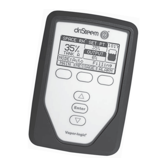
Page 43: Home Screen (Keypad/Display)
SPACE RH SET PT 212˚ Vapor-logic returns to the Home screen on the keypad/display after a user- defined period of idleness. The Home screen displays the items most frequently OUTPUT viewed: Actual space RH or dew point, RH or dew point set point, tank/system TANK A output or steam demand, humidifier mode, and tank activities such as filling... -
Page 44: Status Screen
TANK STATUS 2/24 A Mode Auto Space RH 34% RH MAIN HOME BACK TANK STATUS 3/24 A S p ace RH 34% RH RH set p oint 35% RH HOME MAIN BACK VAPOR-LOGIC VERSION 5 INSTALLATION AND OPERATION MANUAL ®... - Page 45 Duct RH Duct HL switch Open Closed Duct HL set point Duct HL signal °F Tank temperature °C Tank temp signal 2200 Ohms °F Aux temperature °C Aux temp signal Continued VAPOR-LOGIC VERSION 5 INSTALLATION AND OPERATION MANUAL ®...
- Page 46 Current 2 Right cylinder of 2-cylinder model, XT systems only dependent High water probe 2 No water Water Amps Right cylinder of 2-cylinder model, XT systems only * Not an XT menu item VAPOR-LOGIC VERSION 5 INSTALLATION AND OPERATION MANUAL ®...
-
Page 47: Diagnostics Screen
Press the MESSAGE softkey, an operator, or auto-cleared by Vapor-logic. Active messages display or select Messages from the first in the Messages Log, followed by cleared messages, listed in order Diagnostics menu to view the Messages Log. - Page 48 OPERATION Diagnostics screen FIGURE 44-1: VAPOR-LOGIC WEB INTERFACE DIAGNOSTICS SCREEN Click on buttons to activate functions. View messages by clicking on “View Messages” on Clear messages any screen or by opening by clicking here. the Diagnostics screen. VAPOR-LOGIC VERSION 5 INSTALLATION AND OPERATION MANUAL...
- Page 49 Displays as-shipped configuration string Current string Displays current configuration string Serial number Displays humidifier serial number Firmware version Displays current firmware version of Vapor-logic control board Firmware date Displays current firmware date of Vapor-logic control board Model XT systems only Voltage...
- Page 50 Set test run time duration between 0 and 30 minutes. Start Stop * Humidifier test run will not occur if safety circuits (for example, duct high limit switch, airflow proving switch, or safety interlock switch) are not operating correctly. Continued VAPOR-LOGIC VERSION 5 INSTALLATION AND OPERATION MANUAL ®...
- Page 51 • The Messages Log displays a maximum of 10 messages. Cleared messages leave the log first. • If a message event occurs and is not manually or auto cleared during unit operation, the message will stay there until there is demand and the unit is running. VAPOR-LOGIC VERSION 5 INSTALLATION AND OPERATION MANUAL ®...
-
Page 52: Alarms Screen
AL AR M alarm name, date and time of occurrence, plus whether the alarm is active, has been cleared by an operator, or auto-cleared by Vapor-logic. The Alarms Log lists active alarms at the top of the list, followed by cleared Press the ALARM softkey alarms. - Page 53 Flue pressure switch indicates positive pressure in flue. Burner will not ignite when this fault is active. (GTS systems only) Burner tried one or more times to light and did not succeed. Once this fault is active, Vapor-logic locks Burner 1, 2, 3, or 4 fault out the burner and does not try to light it again until fault is cleared.
- Page 54 • The Alarms Log displays maximum 30 alarms. Cleared alarms leave the log first. • If an alarm event occurs and is not manually cleared or auto-cleared during unit operation, the alarm will remain until there is demand and the unit is running. VAPOR-LOGIC VERSION 5 INSTALLATION AND OPERATION MANUAL ®...
-
Page 55: Setup Menu
With a PID loop, you can tune your system for maximum performance using the also require a corresponding hardware change. Vapor-logic firmware will warn you of proportional (Kp), integral (Ki), and derivative (Kd) gain terms. this during the setup process. -
Page 56: The Integral Term
In addition, the proportional term becomes negative and actually starts to subtract from the total system demand. These two terms work in conjunction with each other to bring the humidifier back to set point. VAPOR-LOGIC VERSION 5 INSTALLATION AND OPERATION MANUAL ®... -
Page 57: The Derivative Term
PID band. Small spaces where the humidification system can quickly influence the RH typically benefit from a larger PID band. Rarely should it be set to less than 10%. VAPOR-LOGIC VERSION 5 INSTALLATION AND OPERATION MANUAL ®... -
Page 58: Pid Setup Tips
Then, modify the proportional gain slightly in the same direction the integral gain was changed. RH history data, available for download from the Diagnostics menu, can aid when doing PID loop tuning. VAPOR-LOGIC VERSION 5 INSTALLATION AND OPERATION MANUAL ®... -
Page 59: Water Level Control
fill valve opens until the water level rises to the top probe. Water Chloride corrosion can result from a must remain in contact with the probe surface for three seconds for Vapor-logic variety of causes, including, but not to determine that the water is at the probe’s level. -
Page 60: Float Valve System
Chloride corrosion probe to sense water levels. Damage caused by chloride corrosion is not covered by your DriSteem The float valve system consists of a fill float and a low water cutoff float. warranty. Chloride corrosion can result from a The fill float regulates how much water is added to the tank via a float ball,... -
Page 61: Electrode Steam Humidifiers
Higher water levels cover more electrode surface and result in more steam; lower water levels cover less electrode surface and result in less steam. Since water conductivity and water level both correlate to steam output, DriSteem electrode humidifiers employ an algorithm that monitors conductivity and manages drain and fill events to optimize humidifier performance and provide... -
Page 62: Options And Features
Vapor-logic. Vapor-logic assumes a 70 °F (21 °C) room temperature and uses the glass temperature and the RH in the space being controlled to calculate the dew point (°F or °C) for the space. -
Page 63: Auxiliary Temperature Sensor Option
The transmitter provided with Vapor-logic is calibrated for –20 °F to 160 °F (–29 °C to 71 °C) with output from 4 to 20 mA. For example, a temperature reading of 70 °F (21 °C) should produce a measurement of 12 mA. -
Page 64: Aquastat Set Point Feature
FAN-BASED DISPERSION OPERATION If your humidifier is equipped with a Space Distribution Unit (SDU) or an Area-type fan, it is enabled after the Vapor-logic controller receives a call for humidity and the tank water is approaching boiling temperature. When the humidifier no longer receives a call for humidity, it stops heating and the SDU or Area-type fan continues to run for the time delay period (as defined... -
Page 65: Sensor Offsets
AUTOMATIC DRAIN SEQUENCE, TAP/SOFTENED WATER (See note at right for XT humidifiers.) When configured to run a tap/softened water humidifier with an automatic drain valve, Vapor-logic uses an automatic drain sequence (ADS) to reduce mineral accumulation in the tank and drain line, which decreases tank maintenance. -
Page 66: Draining When Using Softened Water
fill valves. SERVICE INTERVAL The Vapor-logic controller tracks the amount of water converted to steam by the humidifier and the number of hours the humidifier runs. When the amount of steam or hours of run time exceeds the user-defined service interval (pounds,... -
Page 67: Setting Date And Time
Options and features SETTING DATE AND TIME The Vapor-logic controller contains a real-time clock that is used for several features including the drain and flush sequence and alarm logging. If you need to reset the date or time, go to the Setup menu. -
Page 68: Downloading Historical Data
3. Sort all rows by “Time” in ascending order. BACKING UP AND RESTORING DATA Vapor-logic data can be backed up to and restored from a USB flash drive. The backup file contains all information relative to the humidifier, including firmware, user settings, model number, serial number, and the configuration string. -
Page 69: Firmware Updates
DOWNLOADING FIRMWARE UPDATES The Vapor-logic controller can be field upgraded to the latest firmware version via the USB port on the Vapor-logic board. Firmware updates are available at no charge on the DriSteem website. To update your Vapor-logic controller to the latest firmware version, perform the following procedure: 1. - Page 70 Firmware updates Table 66-1: Downloading Vapor-logic firmware updates 1. Click the link shown to the right on the Vapor-logic firmware updates page of www.dristeem.com. If a security window appears, click the Save button. Note: The screenshots in this table depict typical Internet Explorer screens in Windows XP.
- Page 71 OPERATION Firmware updates Table 66-1: Downloading Vapor-logic firmware updates (continued) 6. Click the Browse button in the WinZip Self-Extractor window, and select your USB flash drive as the target location. 7. Click the Unzip button in the WinZip Self-Extractor window.
-
Page 72: Installing Firmware Updates
Step 5. 4. The update process begins immediately and takes up to 1 minute. Wait for the relay on the Vapor-logic board to begin clicking continuously. The water probe LEDs on the board will blink occasionally during the update process. -
Page 73: Test Outputs And Test Run
During testing, the humidifier mode changes to Standby and the tank status changes to Test. TEST RUN Vapor-logic has a test run capability to confirm system functionality. This capability allows a technician to simulate a demand for steam production when there isn’t one (such as when performing routine maintenance). To confirm functionality, go to the test run section of the Diagnostics menu. -
Page 74: Modbus, Bacnet, Lontalk Interoperability
CONNECTIONS 1. If connecting to a Modbus or BACnet MS/TP system, connect Modbus or BACnet system wiring to terminal P7 on the Vapor-logic board (positive to positive, negative to negative). If connecting to a BACnet/IP system, connect BACnet system wiring to the 2. - Page 75 0 to 0 to Water_until_service AV-4 nvoWaterTilSrvc 30011 converted to steam before 2,200,000 1,000,000 next service cycle. * See Note 1 on Page 78. ** See Note 2 on Page 78. Continued VAPOR-LOGIC VERSION 5 INSTALLATION AND OPERATION MANUAL ®...
- Page 76 HR-4 Duct high limit set Duct_high_limit_set_point Write AV-07 nviDuctHLsetPt 0 to 100 0 to 100 40004 point. * See Note 1 on Page 78. ** See Note 2 on Page 78. Continued VAPOR-LOGIC VERSION 5 INSTALLATION AND OPERATION MANUAL ®...
- Page 77 0 to 0 to Pump_1_hours AV-17 nviPump2Hours pump 2 has run since hours hours 40019 100000 100000 reset * See Note 1 on Page 78. ** See Note 2 on Page 78. Continued VAPOR-LOGIC VERSION 5 INSTALLATION AND OPERATION MANUAL ®...
- Page 78 Pump 2 DI-15 0 = No Fault; 1 = VFD_drive_fault BI-13 nvoDriveFault HPS systems only 10015 Fault * See Note 1 on Page 78. ** See Note 2 on Page 78. Continued VAPOR-LOGIC VERSION 5 INSTALLATION AND OPERATION MANUAL ®...
- Page 79 DV-17 Alarm_no_power_vent_airflow BV-17 nvoAlrmPrVentAir DV-18 Alarm_no_combustion_airflow BV-18 nvoAlrmNoCombAir DV-19 Alarm_blocked_flue BV-19 nvoAlrmBlockdFlu DV-20 Alarm_burner_1_failed BV-20 nvoAlrmBurner1 * See Note 1 on Page 78. ** See Note 2 on Page 78. Continued VAPOR-LOGIC VERSION 5 INSTALLATION AND OPERATION MANUAL ®...
- Page 80 Alarm_low_inlet_pressure (HPS) BV-37 nvoAlrmFoaming2 Alarm_Current_Sense1_ Out_ DV-51 BV-51 nvoAlrmCurSense1 Of_Range (XT) Alarm_Current_Sense2_ Out_ DV-52 BV-52 nvoAlrmCurSense2 Of_Range (XT) * See Note 1 on Page 78. ** See Note 2 on Page 78. Continued VAPOR-LOGIC VERSION 5 INSTALLATION AND OPERATION MANUAL ®...
- Page 81 BV-57 nvoAlrmOverCur2 DV-57 Alarm_supply_water_overtemp (HPS) BV-57 nvoAlrmOverCur2 DV-58 Alarm_Supply_Water_2 (XT) BV-58 nvoAlrmSupplyH202 DV-58 Alarm_low_pump_pressure (HPS) BV-58 nvoAlrmSupplyH202 * See Note 1 on Page 78. ** See Note 2 on Page 78. Continued VAPOR-LOGIC VERSION 5 INSTALLATION AND OPERATION MANUAL ®...
- Page 82 Modbus Holding Registers (HR1-HR10) 16 bit read/write Modbus Discrete Input Registers (DI1-DI9) single bit read only Modbus Coil Registers (DV1-DV50) single bit read/write 2. nvi LonTalk SNVTs are write-only; nvo are read-only VAPOR-LOGIC VERSION 5 INSTALLATION AND OPERATION MANUAL ®...
-
Page 83: Multiple-Tank Operation
MULTI-TANK CONTROL INTERFACE Most systems have one Vapor-logic keypad per multi-tank group. This keypad ships with the tank that has the master control board. The keypad (or the Web interface; see note below) can be connected to any humidifier in the multi-tank group. -
Page 84: Tank Grouping To Maximize Efficiency
If the master controller stops operating, the remaining slave tanks continue to run for a short time at the level they were last run, and then quit. VAPOR-LOGIC VERSION 5 INSTALLATION AND OPERATION MANUAL ®... - Page 85 4. When calculating energy, consider heat loss from distribution and piping of steam. 5. Humidifiers within a priority group are load leveled. 6. Humidifiers within a group should have the same energy source. VAPOR-LOGIC VERSION 5 INSTALLATION AND OPERATION MANUAL ®...
-
Page 86: Wiring A Multi-Tank Group Of Humidifiers
On the last board in the series of connected boards, jumper the pins at J1001 (located on the Vapor-logic board next to the RJ11 phone socket, see Page 5). On all other boards, J1001 should not be shunted. -
Page 87: Changing A Priority Group
C ... P). Duplicate tank designations will cause multi-tank mode to operate incorrectly. • Each Vapor-logic board ships with a network IP address of 192.168.1.195. When installing on an Ethernet network, assign each board a unique IP address to avoid conflict with other devices on the network. -
Page 88: Using The Keypad/Display
Tank A screen SPACE RH SET PT 116˚ Note here that Tank A has 0% output because it is not yet at boiling temperature. OUTPUT TANK A MODE:Auto Warm MAIN MESSAGE ALARM VAPOR-LOGIC VERSION 5 INSTALLATION AND OPERATION MANUAL ®... - Page 89 Click on a tank link to view its status. Important: All system tanks must be network-connected via Ethernet for these links to function. Click on the Setup tab to view Multi-tank setup parameters. VAPOR-LOGIC VERSION 5 INSTALLATION AND OPERATION MANUAL ®...
-
Page 90: Troubleshooting Guide
If you have a tank-related or dispersion-related issue, you may also need to refer to those specific product manuals. 3. If you’re still having issues, call DriSteem. If the troubleshooting guide does not help you solve your issue, call DriSteem with the following information available: •... - Page 91 • Field-supplied remote fault indicator lamp is burned • Check if at remote indicator light is burned out; replace if needed. • Remote fault Vapor-logic dry contact is not • Check dry contact continuity (Vapor-logic terminal switching P12) for contact closure.
- Page 92 -- Calibrate transmitter or humidistat if necessary. • Isolation control board by others may not be compatible. Alarm: Consult DriSteem. Aux temp sens out of range • SDU blower or airflow proving switch is • Check SDU for proper wiring.
- Page 93 • Low conductivity water supply • If conductivity is less than 30 μS/cm add ¼-½ tab sodium bicarbonate (i.e., Alka Seltzer) to increase conductivity. Consult DriSteem for further advice. • Humidifier interlock switches and/or over- • Verify that switch or thermostat is wired.
- Page 94 • Excessive condensate is draining into the tank • Consult DriSteem to increase the amount of water that can be converted to steam before receiving a fault. For XT humidifiers, see Check cylinder / high water on Page 47 of Table 45-1.
- Page 95 • Clean or replace drain valve if an obstruction in the valve does not allow complete closure. • Close manual drain valve if it is open. • If Vapor-logic shorted output to fill valve coil, replace board or drain coil. • Malfunctioning level control system •...
- Page 96 • Reduce demand signal. end-of-season drain • Vapor-logic setup • Verify in Setup menu Vapor-logic is set for end-of-season drain. • Drain valve • Valve not wired, or incorrectly wired, to control board. • Check 24 VAC across valve coil during test cycle.
- Page 97 GTS, STS or LTS systems only: • Clean. • Dirty heat exchanger GTS systems only: • Clean or adjust as appropriate. See tank manual for instructions. • Dirty burners • Low gas pressure Continued VAPOR-LOGIC VERSION 5 INSTALLATION AND OPERATION MANUAL ®...
- Page 98 • Mineral buildup on heaters • The humidifier may be undersized. Increase humidifier capacity or replace with larger humidifier. Consult DriSteem. • Inspect tank for severe mineral buildup on or around heater. Increase skim duration, frequency of drain cycle, and/or frequency of cleaning.
- Page 99 • Check if the heater over-temperature has been tripped. Reset if necessary. • Humidity control input type not the same as • Check Vapor-logic control board connections P11 and P13. Vapor-logic firmware Consult DriSteem. • Vapor-logic not in Auto mode •...
- Page 100 • Check for proper Vapor-logic control settings: RH set point, high limit set point, cycle rate, PID tuning, etc. • Relocate poorly located control components. See “Sensor placement” on Page 26.
- Page 101 • Steam valve inoperable • Valve not opening fully. Check signal to valve. • Steam trap blocked • Trap not passing condensate. • Scale coated heat exchanger • Clean heat exchanger. VAPOR-LOGIC VERSION 5 INSTALLATION AND OPERATION MANUAL ®...
-
Page 102: Replacement Parts
Keypad/display (includes printed circuit board, LCD display screen, membrane switch, front and back of plastic 408495-011 cover) 27" (686 mm) 408490-014 Keypad/display communication cable (contact DriSteem for lengths other than 27" (686 mm) and 60" (1524 mm) 60" (1524 mm) 408490-009 Molex connector plug, 2-position 406246-002... - Page 103 OPERATION Replacement parts FIGURE 99-1: VAPOR-LOGIC REPLACEMENT PARTS Main board Keypad display Molex connector plug (2-position shown) p g ( p LonTalk card VAPOR-LOGIC VERSION 5 INSTALLATION AND OPERATION MANUAL ®...
-
Page 104: Warranty
DriSteem is an ISO 9001:2000 certified company breach of contract, negligence, strict liability in tort, or any other legal theory, even if DriSteem has notice of the possibility of such damages.
Need help?
Do you have a question about the VAPOR-LOGIC and is the answer not in the manual?
Questions and answers