
Related Manuals for DriSteem Vapor-logic3


Summary of Contents for DriSteem Vapor-logic3
- Page 1 ® Va p or-lo g i c H umi di f i e r C ont r ol S ys te m Ins tallatio n a n d Operation Man u al...
-
Page 3: Table Of Contents
Ta b l e o f c o n t e n t s Overview IMPORTANT Product overview ......... . 1 Read and save these instructions. - Page 4 Installation and Operation Manual...
-
Page 5: Product Overview
Accurate, responsive microprocessor control Vapor-logic provides comprehensive control for DRI-STEEM humidifiers. With extensive capabilities and easy-to-use keypad, the Vapor-logic efficiently controls all humidifier functions. Navigating the keypad to adjust or review humidifier functions is an intuitive process of walking through easily read screen menus. You will find no other controller in the humidifier market able to provide such functionality, ease of use, and accurate relative humidity (RH) control. -
Page 6: Summary Of Features
S u m m a r y o f f e a t u r e s Summary of features Self-diagnostic test at startup End-of-season automatic drain allows time-stamped alarm tracking and three ways to program drain and flush cycles: 1. -
Page 7: Control Input Signals
C o n t r o l i n p u t s i g n a l s DRI-STEEM offers three control options for all its humidification systems controlled by Vapor-logic : on-off control, demand signal control, and transmitter control. On-off control On-off control—the simplest control scheme—does exactly what its name implies: the output device turns fully on, then fully off. - Page 8 C o n t r o l i n p u t s i g n a l s , c o n t i n u e d Transmitter control With transmitter control, the Vapor-logic board receives a linear signal that corresponds to the actual humidity level measured in the space being controlled.
-
Page 9: Tp Modulation
TP modulation (electric humidifiers) The standard form of modulation with an electric humidifier is time proportioning (TP) modulation. With TP modulation, the outputs cycle on and off at a certain rate to approximate humidifier demand as the example below illustrates. To calculate the example, imagine that each contactor represents 25% of the output of the humidifier. -
Page 10: Ssr Modulation
S S R m o d u l a t i o n DRI-STEEM electric humidifiers are available with two basic types of solid state relay (SSR) modulation: SSR modulation with contactors and 100% SSR modulation. SSR modulation with contactor sequence On systems that employ SSR modulation with contactors, the operation of the unit is the same as with TP modulation. -
Page 11: Valve And Burner Modulation
STS and LTS valve modulation With a valve system, the demand signal simply determines how far the valve strokes. In other words, if the system demand is 25%, the valve strokes 25%. GTS burner modulation A GTS burner assembly consists of a variable speed blower, a constant air/gas ratio modulating gas valve, and a burner. -
Page 12: Water Level Control - Standard Water Models
Probe system Figure 8-1: Water level control for standard Standard or softened water systems use conductivity probes to water systems measure and control water levels for optimum operating efficiency. Water conductivity must be at least 100 μS/cm for the probe system to operate. -
Page 13: Water Level Control - Di/Ro Models
Float valve system Figure 9-1: DI/RO water systems (except for steam injection) use a float valve Water level control for DI/RO water systems system to control water levels for optimum operating efficiency. DI/RO systems are used where water/steam purity is important, where demineralized water is needed to improve performance or Fill valve lessen maintenance requirements, or where a potable water source... -
Page 14: Installation Installing The Keypad/Display
Keypad/display installation The six-wire RJ-11 plug/cable provides AC power to the keypad/ display and completes the FTT-10A digital communication between the keypad/display and the Vapor-logic control board. Note that the keypad/display requires an ambient temperature range of 32 °F to 122 °F (0 °C to 50 °C) to operate properly. Exceeding these limits can result in poor display performance and/or damage to the unit. -
Page 15: Main Control Board Connections
M a i n c o n t r o l b o a r d c o n n e c t i o n s Figure 11-1: Vapor-logic main control board Testing input configuration: Measure 1-5 VDC across terminals 22-23 for 4-20 mA signal by others or 4-20 mA... - Page 16 M a i n c o n t r o l b o a r d c o n n e c t i o n s Vapor-logic main control board connections Wire terminal supplies 24 VAC to power the Vapor-logic control board.
- Page 17 M a i n c o n t r o l b o a r d c o n n e c t i o n s , c o n t i n u e d Important note about J14/J17, J15/J18, and J16/J19 Figure 13-1: All external wiring connection diagrams show shunts on J14/J17, Vapor-logic...
- Page 18 M a i n c o n t r o l b o a r d c o n n e c t i o n s , c o n t i n u e d Wire terminal connection allows for remote fault indication via isolated relay contacts (1 amp max.).
-
Page 19: Gts Expansion Board Connections
G T S e x p a n s i o n b o a r d c o n n e c t i o n s Figure 15-1: GTS expansion board VL3-OM-003 ¼" push-on connector for earth ground Combustion air blower 2 control max.) blower... - Page 20 G T S e x p a n s i o n b o a r d c o n n e c t i o n s , c o n t i n u e d Important: When this jumper is left open, the GTS expansion module is configured to control burners 1 and 2.
-
Page 21: Vaporstream Expansion Board Connections
Va p o r s t r e a m e x p a n s i o n b o a r d c o n n e c t i o n s 1¼" (6.4 mm) push-on connector for earth ground Figure 17-1: Vaporstream expansion board Not used... -
Page 22: Installation Checklist
I n s t a l l a t i o n c h e c k l i s t Before installing your Vapor-logic control system, review this checklist to ensure proper installation of the product. Failure to follow the recommendations listed below could result in failure or damage to the humidifier or microprocessor. -
Page 23: Typical Installation
Ty p i c a l i n s t a l l a t i o n Figure 19-1: Typical humidification system layout Line voltage Dispersion assembly 24 VAC control wiring Electrical supply Keypad/display Control cabinet OM-3007 Typical humidifier DRI-STEEM Vapor-logic... -
Page 24: General Wiring Procedures
IMPORTANT: Proper wiring prevents electrical noise Do not use shielded (screened) cable for Electrical noise can produce undesirable effects on electronic probe wiring. control circuits, thereby affecting controllability. Electrical noise is generated by electrical equipment such as inductive loads, electric motors, solenoid coils, welding machinery, or fluorescent light circuits. - Page 25 c o n t i n u e d IMPORTANT: room/duct humidity and temperature transmitters, or control Do not use shielded (screened) cable for signal input connections from a building control system, use probe wiring. 18-gauge (1 mm ) (minimum) plenum-rated, twisted-pair wire, with cable shield (screen) wire for grounding.
-
Page 26: Control Cabinet Connections
C o n t r o l c a b i n e t c o n n e c t i o n s Control cabinet installation and wiring The Vapor-logic control board is shipped mounted with all internal wiring completed within a control cabinet. All software is custom programmed into your Vapor-logic system according to the original order requirements. - Page 27 C o n t r o l c a b i n e t c o n n e c t i o n s , c o n t i n u e d Vaporstream control cabinet Figure 23-1: Standard control cabinets for VLC and VLDI Vaporstream control cabinet penetration locations are shipped loose.
- Page 28 C o n t r o l c a b i n e t c o n n e c t i o n s , c o n t i n u e d STS and LTS control cabinet Figure 24-1: Control cabinets for all STS and LTS STS and LTS control cabinet penetration locations...
-
Page 29: Sensor Device Placement And Humidity Control Overview
Recommended sensor locations Other factors that affect humidity control Sensor or transmitter location has a significant impact on Unsatisfactory humidity control may involve humidifier performance. In most cases, we recommend that you do more than the controller’s capability to not interchange duct and room humidity devices. Room humidity control the system. -
Page 30: Wiring Sensor Devices
Figure 26-1: Vapor-logic input wiring detail of a typical system configuration OM-2027 Notes: limit switch, and a temperature compensation transmitter (4-20 mA). See the following pages in this manual for other input wiring instructions. Pages 11–14 in this manual. IMPORTANT Consult control cabinet wiring diagram. - Page 31 I n s t a l l a t i o n : W i r i n g d e t a i l Calculation of transmitter % RH Wiring on-off humidistats DRI-STEEM provides two types of on-off control: wall-mounted humidistat and duct-mounted humidistat.
- Page 32 Variable air volume (VAV) option This option is identified as a “V” in the third-from-last place of your program code configuration string (for example: EV11400285A7 OX). See Pages 32-33 for more information about the program code configuration string. When the VAV control option is requested, DRI-STEEM provides a duct mounted humidity transmitter (4 to 20 mA output, 0 to 100% RH range).
- Page 33 Temperature compensation offset option Figure 29-1: Temperature transmitter wiring This option is identified as a “T” in the second-from-last place of your program code configuration string (for example: 21 VDC EV11400285A7O sensor window When selected as an option, DRI-STEEM provides a temperature mount C.I.-T184H compensation (temp.
- Page 34 Temperature compensation transmitter placement To place the temperature compensation transmitter, follow these steps. See Figure 30-1 below. 1. Position the temperature compensation transmitter control box on a wall adjacent to a window frame facing north or northeast. 2. Place flat surface of temperature sensor tip on lower corner of glass surface.
- Page 35 Changing control input Figure 31-1: You can configure the control input on the Vapor-logic board to Vapor-logic main control board detail read either an external demand signal or RH signal. It also can read different types of analog signals from building automation systems, humidistats, or RH transmitters.
-
Page 36: Configuration String Programming
C o n f i g u r a t i o n s t r i n g p r o g r a m m i n g I m p o r t a n t : Vapor-logic configuration string * For Vapor-logic... - Page 37 C o n f i g u r a t i o n s t r i n g p r o g r a m m i n g , c o n t i n u e d I m p o r t a n t : H Operating mode * For Vapor-logic...
-
Page 38: Interoperability Using Lontalk
I n t e r o p e r a b i l i t y u s i n g L o n Ta l k The Vapor-logic controller uses LonTalk as its field bus protocol, which enables previously disparate systems and products to interoperate by providing communication through Standard Network Variable Types or SNVTs (“snivits”). - Page 39 C o n n e c t i n g L o n Ta l k I m p o r t a n t : Connect the keypad/display LonMaker prohibits commissioning into Requirements: Lon network manager software (user should be domain 0 (zero).
- Page 40 C o n n e c t i n g L o n Ta l k , c o n t i n u e d Figure 36-1: LonMaker example Figure 36-2: LonMaker New Device Wizard Installation and Operation Manual...
- Page 41 C o n n e c t i n g L o n Ta l k , c o n t i n u e d 3. If using the service pin to identify the board on the network, Figure 37-1: press the service pin (next to the blinking LED on the main Display service pin and LED locations board).
- Page 42 Table 38-1: LonTalk network variable inputs (nvi) available with Vapor-logic SNVT Description nviTimeStamp Set the date and time of day. nviMode 1. Auto 2. Standby 3. Drain (manual) Set the humidity set point for the space being humidified. Set the duct high limit set point for VAV option. nviSetOutputPcnt Set the steam output as a percentage of the humidifier’s total capacity.
- Page 43 Table 39-1: LonTalk network variable outputs (nvo) available with Vapor-logic SNVT Description nvoTimeStamp Read the current date and time that the unit is set to. nvoMode 1. Auto 2. Standby 3. Drain (manual) Read the relative humidity content of the air in the space being humidified (percent RH). Read the humidity set point for the space being humidified (percent RH).
- Page 44 Table 40-1 (continued): LonTalk network variable outputs (nvo) available with Vapor-logic SNVT Description nvoAlarm These outputs are expressed using a 64-bit map. The user will see a 64-bit number of 1s and 0s. For 1000000000000000000000000000000000000000000000000000000000000000 Bit map positions 0–30 are identified below; bit map positions 31–63 are for factory use only; disregard See Pages 61-62 for fault definitions.
- Page 45 Table 41-1: Vapor-logic digital input states (nvoDigital_IO) Bit map position Device Airflow External On-off SDU or proving interlock high Area For factory use only. Disregard states for these bit map positions switch switch limit Type fan switch control Open Open Fan off airflow State...
-
Page 46: Multiple-Tank Configurations
M u l t i p l e t a n k c o n f i g u r a t i o n s : I n t r o d u c t i o n I m p o r t a n t : One master controller, multiple slave tanks Information on this page applies to Vapor-logic... - Page 47 M u l t i p l e t a n k c o n f i g u r a t i o n s : I m p o r t a n t : Priority groups Information on this page applies to All humidifier tanks in a multi-tank group are assigned to a priority Vapor-logic firmware versions 5.x.x...
- Page 48 M u l t i p l e t a n k c o n f i g u r a t i o n s : I m p o r t a n t : Tank wear leveling Information on this page applies to The master controller monitors tank wear and assigns steam Vapor-logic...
- Page 49 M u l t i p l e t a n k c o n f i g u r a t i o n s : I n s t a l l a t i o n I m p o r t a n t : To install a multi-tank group, read the following instructions: Information on this page applies to 1.
- Page 50 M u l t i p l e t a n k c o n f i g u r a t i o n s : M u l t i - t a n k s t a t u s s c r e e n Figure 46-1: Multi-tank status screen Current total output is 27% of system capacity...
- Page 51 M u l t i p l e t a n k c o n f i g u r a t i o n s : I m p o r t a n t : Using the keypad/display Information on this page applies to The keypad/display communicates with every humidifier tank's Vapor-logic...
- Page 52 M u l t i p l e t a n k c o n f i g u r a t i o n s : C o n f i g u r i n g h u m i d i f i e r t a n k s I m p o r t a n t : Humidifier tanks ordered as a multi-tank group are configured at the factory.
- Page 53 M u l t i p l e t a n k c o n f i g u r a t i o n s : C o n f i g u r i n g h u m i d i f i e r t a n k s I m p o r t a n t : to communicate with the same (renamed) tank.
-
Page 54: Multiple-Tank Configuration String
M u l t i - t a n k c o n f i g u r a t i o n s t r i n g I m p o r t a n t : Vapor-logic configuration string * For Vapor-logic firmware versions other... - Page 55 M u l t i - t a n k c o n f i g u r a t i o n s t r i n g , c o n t i n u e d I m p o r t a n t : H Operating mode * For Vapor-logic firmware versions other...
-
Page 56: Using The Keypad
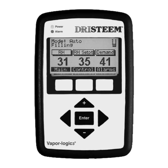
U s i n g t h e k e y p a d Components of the keypad/display Figure 52-1: Vapor-logic keypad/display The Vapor-logic keypad/display (see Figure 52-1) consists of : – Four arrow keys – An Enter key – Three soft keys The three soft keys are located directly beneath the LCD. - Page 57 U s i n g t h e k e y p a d , c o n t i n u e d The menu system The Vapor-logic keypad/display organizes the control and monitoring of the humidification system into six top-level menus: Each of these menus controls or monitors a different aspect of the humidifier.
-
Page 58: Menu Structure Overview
Main Menu (Soft key) Idle (Soft key) Main – Returns to the Main Menu screen (Soft key) Control – Switches display to the Control Modes screen (Soft key) Alarms – Switches display to the Alarms screen 1 Status (Soft key) Main – Returns to the Main Menu screen (Soft key) Back –... - Page 59 Main Menu (Soft key) Idle (Soft key) Main – Returns to the Main Menu screen (Soft key) Control – Switches display to the Control Modes screen (Soft key) Alarms – Switches display to the Alarms screen 1 Status (Soft key) Main – Returns to the Main Menu screen (Soft key) Back –...
-
Page 60: Idle Screen
M a i n m e n u : I d l e s c r e e n Idle Screen The Idle screen provides a convenient way to monitor the humidifier’s basic operation. Depending on system options, the system set point, the actual space condition, and/or the system demand predominantly appear on the Idle screen. - Page 61 I d l e s c r e e n s t a t u s m e s s a g e s Table 57-1: Idle screen status messages xref Readout display Description Filling The unit is filling with water. Skimming The unit completed a fill cycle and now is skimming.
-
Page 62: Status Screen
M a i n m e n u : S t a t u s s c r e e n Status Use the Status screen to view the operating parameters of the humidification system. The configuration string determines which parameters appear. -
Page 63: Control Modes Screen
M a i n m e n u : C o n t r o l m o d e s s c r e e n Control modes Use the Control Modes screen to set the operational mode of the humidifier. -
Page 64: Alarms Screen
M a i n m e n u : A l a r m s s c r e e n Alarms screen Use the Alarms screen to clear system alarms and to view the alarm log. To scroll through the alarm log, use the vertical arrow keys. The alarm log contains a record of the previous 10 faults (alarms) that occurred on the humidifier. -
Page 65: Fault Messages
F a u l t m e s s a g e s Tank level fault (previous name: Fill Time Fault) The Vapor-logic controller keeps track of how much water converts to steam. If this total amount exceeds a preset limit without energizing the fill valve, the controller assumes a low water condition is present. - Page 66 F a u l t m e s s a g e s , c o n t i n u e d Tank level fault (Tank Level Flt) (previous name: Fill Time Flt) The unit has run too long without the fill valve opening. Fill valve may be stuck open, heating devices may be damaged, or heater control may be faulty.
-
Page 67: System Set Up Screen
M a i n m e n u : S y s t e m S e t U p s c r e e n System Set Up Use the System Set Up screen to set the operational parameters of the humidifier. - Page 68 M a i n m e n u : S e t U p s c r e e n , c o n t i n u e d Table 64-1: Set Up menu information Set Up menu parameter Set Up menu description Range Default...
-
Page 69: Adjusting Set Point
A d j u s t i n g s e t p o i n t Adjusting set point through the Set Up menu You can adjust your unit’s set point using the Set Up menu, which is under the Main menu (see the menu structure diagram on Pages 54-55). -
Page 70: Pid Tuning
Adjusting set point with PID loop When your unit is equipped with a humidity or dew point transmitter, you can adjust and control the set point through the keypad/display, using a proportional, integral, and derivative (PID) control loop. With a PID loop, you can “tune” your system for maximum performance using the proportional (Kp), integral (Ki), and derivative (Kd) gain terms. - Page 71 The integral term The integral term is an accumulation of RH error over time multiplied by the integral gain. The way this works is as follows: every ½ second when the demand is updated, the instantaneous RH error (RH set point – actual RH) is added to a temporary variable that accumulates the error.
- Page 72 The derivative term The derivative term is the measured change in error over time multiplied by the derivative gain (differentiating error with respect to time). Its basic operation is as follows: if the actual measured RH is below set point and is rising, the derivative term subtracts from the demand in anticipation of the approaching set point.
- Page 73 PID setup tips Kp = Proportional gain factor A large PID band (10% to 20%) yields tighter and more stable Ki = Integral gain factor control with longer response times. A small PID band produces Kd = Derivative gain factor quicker response times, but control may become unstable if the RH regularly goes outside the band.
-
Page 74: Vav, Temp Comp Control Operation
VA V, t e m p c o m p c o n t r o l o p e r a t i o n VAV control With VAV control, the system is equipped with a duct RH transmitter. This transmitter monitors the RH in the duct downstream from the steam dispersion unit and transmits the duct RH to the Vapor-logic controller. -
Page 75: Dew Point Control, Tank Preheat Operation
o p e r a t i o n Dew point control Dew point control functions in exactly the same way as RH control except the dew point is being measured instead of the RH. The dew point transmitter sends a signal to the Vapor-logic controller. -
Page 76: Aquastat, Freeze Protection Operation
A q u a s t a t , f r e e z e p r o t e c t i o n o p e r a t i o n Aquastat operation The aquastat set point is the minimum tank temperature the Vapor-logic controller should maintain when there is no call for humidity. -
Page 77: Sdu/Fan Operation, Sensor Offsets
SDU operation If your humidifier is equipped with a Space Distribution Unit (SDU) or an Area-type fan, it is enabled after the Vapor-logic receives a call for humidity and the tank temperature rises above 150 °F (66 °C). When the humidifier no longer receives a call for humidity, it stops heating and the SDU or Area-type fan continues to run for the SDU Duration to ensure that steam gets dispersed. -
Page 78: Automatic Drain Sequence (Ads)
Automatic drain sequence for potable water (not softened) Table 74-1: System-dependent defaults for When configured to run a potable water humidifier with an automatic drain sequence (ADS) automatic drain valve, Vapor-logic uses an automatic drain sequence (ADS) to help reduce mineral accumulation in the tank ADS duration AFS duration Humidifier... - Page 79 c o n t i n u e d When the ADS mode is set to “Interval, ” the humidifier enters a drain and flush sequence after a user-defined interval of time, ignoring the amount of water converted to steam. The interval is established by setting the “ADS day, ”...
-
Page 80: End-Of-Season Drain
Draining when using softened water When using softened water and when the program code indicates either “S” or “T” for the “Type of water level control” being used (see the configuration string nomenclature on Pages 32 and 33), then draining occurs for a one-minute duration every 28 days to remove residue from the drain valve mechanism. -
Page 81: Service Interval, Setting Date And Time
t i m e Service interval The Vapor-logic controller tracks the amount of water converted to steam by the humidifier. When the amount of water converted to steam exceeds the Service set point (a user-defined amount of water in pounds or kilograms adjusted in the system Set Up screen), the “Service Humidifier”... -
Page 82: Diagnostics Screen
M a i n m e n u : D i a g n o s t i c s s c r e e n Diagnostics The Diagnostics screen allows you to monitor all of the analog and discrete inputs to the Vapor-logic control system. -
Page 83: Reports Screen
M a i n m e n u : R e p o r t s s c r e e n Reports The Reports menu displays up to four report options to help the user gain historical data on the humidification system. Information contained in each report is explained below. - Page 84 M a i n m e n u : R e p o r t s s c r e e n , c o n t i n u e d RH/dew point/demand graph Figure 80-1: Oscillating RH demand graph The RH (or dew point or demand) graph provides a graphical depiction of RH change over time.
-
Page 85: Start-Up Checklist
S t a r t - u p c h e c k l i s t Your humidification system may not have all of the options listed below. If an item does not apply to your system, skip to the next item and continue the process. - Page 86 S t a r t - u p c h e c k l i s t , c o n t i n u e d Start-up checklist (continued) ☐ Check the flush duration (default is 1 minute). ☐ Check the RH set point and set at the desired level. ☐...
- Page 87 S t a r t - u p c h e c k l i s t , c o n t i n u e d Start-up checklist (continued) ☐ Confirm that the high limit humidistat input is closed or that the variable air volume (VAV) control system high limit transmitter is connected.
-
Page 88: Troubleshooting
Tr o u b l e s h o o t i n g i n t r o d u c t i o n 1. Review troubleshooting index. If you have a control-related problem, first check the problem list in this section. - Page 89 I n d e x t o t r o u b l e s h o o t i n g g u i d e Below is an index to possible control-related problems described on the following pages. To find solutions, refer to the page number.
-
Page 90: Green Power Indicator Light Is Off
Tr o u b l e s h o o t i n g g u i d e Table 86-1: Vapor-logic troubleshooting guide Problem Possible cause Action Green power indicator light is off Green power light breaker tripped Vapor-logic terminal block J22 (see Pages 11 and 14). -
Page 91: Fill Fault
Tr o u b l e s h o o t i n g g u i d e Table 87-1: Vapor-logic troubleshooting guide Problem Possible cause Action Fill fault Tank is not full In fill sequence, Vapor-logic allows 40 minutes for the water reversed. -
Page 92: Drain Fault
Tr o u b l e s h o o t i n g g u i d e Table 88-1: Vapor-logic troubleshooting guide Problem Possible cause Action Drain fault When in automatic drain sequence or end-of-season drain, Vapor-logic allows 20 minutes for the water level to drop from on control board. -
Page 93: Ll Probe Fault
Tr o u b l e s h o o t i n g g u i d e Table 89-1: Vapor-logic troubleshooting guide Problem Possible cause Action Low level probe fault (LL probe fault) conductivity. Consult DRI-STEEM for further advice. The lowest probe showed no contact with probes. -
Page 94: Clean Probes And Tank Message
Tr o u b l e s h o o t i n g g u i d e Table 90-1: Vapor-logic troubleshooting guide Problem Possible cause Action ” ” Clean probes and tank message 100 μS/cm. If conductivity is low, add salt to increase appears on idle screen conductivity. -
Page 95: Probe Assembly Fault
Tr o u b l e s h o o t i n g g u i d e Table 91-1: Vapor-logic troubleshooting guide Problem Possible cause Action Probe assembly fault (Probe Assy Flt) assembly xreftag or over-temperature thermostat is on. Tank temperature fault of sensor and voltages (see Page... -
Page 96: Gas Valve [No.] Fault
Tr o u b l e s h o o t i n g g u i d e Table 92-1: Vapor-logic troubleshooting guide Problem Possible cause Action xreftag pressure to manifold per rating plate. “ ” position and that there is power to the valve. -
Page 97: Unit Does Not Fill With Water
Tr o u b l e s h o o t i n g g u i d e Table 93-1: Vapor-logic troubleshooting guide Problem Possible cause Action Unit does not fill with water. xreftag does not open, verify proper 24 VAC (terminals 1 and 2) to fill valve. -
Page 98: Fill Valve Does Not Close
Tr o u b l e s h o o t i n g g u i d e Table 94-1: Vapor-logic troubleshooting guide Problem Possible cause Action Fill valve does not close. position, reset to automatic. drain valve. xreftag does not allow complete closure. -
Page 99: Reduced Or No Output
Tr o u b l e s h o o t i n g g u i d e Table 95-1: Vapor-logic troubleshooting guide Problem Possible cause Action Reduced or no output (even though water level is correct). to operate, e.g., duct humidistats, airflow proving switch, etc. -
Page 100: Heater Burnout
Tr o u b l e s h o o t i n g g u i d e Table 96-1: Vapor-logic troubleshooting guide Problem Possible cause Action Heater burnout xreftag capacity or replace with larger humidifier. Consult DRI-STEEM. heater. Increase skim duration, frequency of drain cycle, and/or frequency of cleaning. -
Page 101: Humidity Below Desired Level
Tr o u b l e s h o o t i n g g u i d e Table 97-1: Vapor-logic troubleshooting guide Problem Possible cause Action Humidity is below desired level. required humidity level. additional humidifier. xreftag clean, repair, or replace as needed. drain, repair as needed. -
Page 102: Humidity Above Set Point
Tr o u b l e s h o o t i n g g u i d e Table 98-1: Vapor-logic troubleshooting guide Problem Possible cause Action Humidity above set point xreftag humidity transmitters Pages 26–33) or malfunctioning, repair or recalibrate. needed. -
Page 103: Tank Does Not Heat Up
Tr o u b l e s h o o t i n g g u i d e Table 99-1: Vapor-logic troubleshooting guide Problem Possible cause Action Tank does not heat up switch located under heater wiring cover tripped (Vaporstream models only) xreftag vent switch (GTS only). -
Page 104: Unit Does Not Perform End-Of-Season Drain
Tr o u b l e s h o o t i n g g u i d e Table 100-1: Vapor-logic troubleshooting guide Problem Possible cause Action Unit does not perform end-of- season drain. program xreftag Humidifier tank has proper water level and is always warm water temperature within range of 40 ºF to 180 ºF (4 ºC to 82 ºC). -
Page 105: Replacement Parts
R e p l a c e m e n t p a r t s Figure 101-1: Figure 101-2: Vapor-logic replacement parts Vapor-logic replacement parts OM-3007-3 3.x.x 4.x.x 5.x.x 6.x.x VL3-OM-011 7.x.x Table 101-1: Vapor-logic replacement parts Part no. for Part no. -
Page 106: Notes
N o t e s Installation and Operation Manual... - Page 107 N o t e s DRI-STEEM Vapor-logic...
-
Page 108: Warranty
For the most current product information, defective product, or the refund of the purchase price, at DRI-STEEM’s election. visit our Web site: www.dristeem.com DRI-STEEM shall not be liable for any costs or expenses, whether direct or indirect, associated with the installation, removal or reinstallation of any defective product.
Need help?
Do you have a question about the Vapor-logic3 and is the answer not in the manual?
Questions and answers