Fujitsu PRIMERGY TX2540 M1 Operating Manual
Hide thumbs
Also See for PRIMERGY TX2540 M1:
- Upgrade and maintenance manual (414 pages) ,
- Upgrade and maintenance manual (422 pages)

Related Manuals for Fujitsu PRIMERGY TX2540 M1


Summary of Contents for Fujitsu PRIMERGY TX2540 M1
- Page 1 Operating Manual - English FUJITSU Server PRIMERGY TX2540 M1 Operating manual Edition February 2014...
-
Page 2: Copyright And Trademarks
– The contents of this manual may be revised without prior notice. – Fujitsu assumes no liability for damages to third party copyrights or other rights arising from the use of any information in this manual. – No part of this manual may be reproduced in any without the prior written permission of Fujitsu. - Page 3 Before reading this manual For your safety This manual contains important information for safely and correctly using this product. Carefully read the manual before using this product. Pay particular attention to the accompanying manual "Safety Notes and Regulations" and ensure these safety notes are understood before using the product.
- Page 4 Please consult the sales staff of Fujitsu if intending to use this product for high safety use. Measures against momentary voltage drop This product may be affected by a momentary voltage drop in the power supply caused by lightning.
- Page 5 Only for the Japanese market: Although described in this manual, some sections do not apply to the Japanese market. These options include: – CSS (Customer Self Service) Operating Manual TX2540 M1...
- Page 6 Operating Manual TX2540 M1...
-
Page 7: Table Of Contents
Contents Introduction ......11 Documentation overview ....12 Concept and target groups for this manual . - Page 8 Contents Connecting the server to the mains ....58 5.5.1 Using cable ties ......59 Notes on connecting/disconnecting cables .
- Page 9 Contents Flickering stripes on monitor screen ... . . 89 No screen display or display drifts ....89 No mouse pointer displayed on screen .
- Page 10 Contents Operating Manual TX2540 M1...
-
Page 11: Introduction
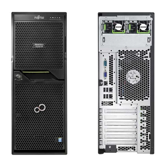
Introduction The PRIMERGY TX2540 M1 is a perfect server for SMEs, branch offices or virtualized environments in an attractive design. It offers dual processor performance combined with expandability and energy efficiency. With up to 24 2.5-inch hard disk drives, you can save on an external storage unit. The high energy efficiency minimizes costs. -
Page 12: Documentation Overview
Introduction Documentation overview More information on your PRIMERGY TX2540 M1 can be found in the following documents: – "Quick Start Hardware - FUJITSU Server PRIMERGY TX2540 M1" – "ServerView Quick Start Guide" – "Safety Notes and Regulations" manual " 安全上のご注意 " for the Japanese market –... -
Page 13: Concept And Target Groups For This Manual
This operating manual is intended for those responsible for installing the hardware and ensuring that the system runs smoothly. It contains all the information you need to put your PRIMERGY TX2540 M1 into operation. To understand the various expansion options, you will need to be familiar with the fields of hardware and data transmission and you will require a basic knowledge of the underlying operating system. - Page 14 Introduction Operating Manual TX2540 M1...
-
Page 15: Functional Overview
Functional overview This section provides information on the features and technical data of the FUJITSU Server PRIMERGY TX2540 M1 server. For information on key characteristics and layout of the system board, see the "FUJITSU Server PRIMERGY TX2540 M1 Server Upgrade and Maintenance Manual". - Page 16 (for the Japanese market) System board The features of the system board are described in the "FUJITSU Server PRIMERGY TX2540 M1 Server Upgrade and Maintenance Manual", the setup possibilities are described in the "D3099 BIOS Setup Utility for FUJITSU Server PRIMERGY TX2540 M1 Reference Manual".
- Page 17 Functional overview Hard disk drives For the server is available in two chassis variants: For up to 8 3.5-inch SAS/SATA HDD ● Up to four SAS/SATA HDD modules can be used in the standard HDD cage. Each HDD module can accommodate a SAS/SATA HDD with a maximum height of 1 inch.
- Page 18 Further information on other SAS/SATA RAID controllers (e.g. for operating external SAS/SATA hard disk drives or tape drives) is available on the Fujitsu manuals server under Industry Standard Servers - Expansion Cards - Storage Adapters - LSI SAS / SCSI RAID Controllers.
- Page 19 A mix of 450 W and 800 W hot-plug PSUs is not allowed. If one of two hot-plug PSU is defective, the other guarantees unimpaired operation. The defective power supply module can be replaced during operation (see the "FUJITSU Server PRIMERGY TX2540 M1 Server Upgrade and Maintenance Manual").
- Page 20 "hides" the defective system components. The PDA (Prefailure Detection and Analysis) technology from Fujitsu analyzes and monitors all components that are critical for system reliability. The SAS/SATA RAID controller supports different RAID levels and increase the availability and data security of the system.
- Page 21 Functional overview iRMC S4 with integrated management LAN connector The iRMC S4 (integrated Remote Management Controller) is a Baseboard Management Controller (BMC) with integrated management LAN connector and expanded functionality that was previously only available with additional plug-in cards. In this way, the iRMC S4 enables complete control of PRIMERGY servers, regardless of system status, and thus particularly the control of PRIMERGY servers that are in the "out-of-band"...
- Page 22 Functional overview More information about the iRMC S4 can be found in the "iRMC S4 - integrated Remote Management Controller" user guide (on the Fujitsu manuals server under Industry Standard Servers - Software - ServerView Suite - Out-Of-Band Management). Operating Manual...
- Page 23 Server management is implemented using the ServerView Operations Manager supplied and the PDA (Prefailure Detection and Analysis) technology from Fujitsu. PDA reports the threat of a system error or overload at an early stage, allowing preventive measures to be taken.
- Page 24 BIOS update. With the iRMC (integrated Remote Management Controller) on the system board, the PRIMERGY TX2540 M1 server can also be maintained and serviced remotely. This enables remote diagnosis for system analysis, remote configuration and remote restart should the operating system or hardware fail.
- Page 25 ServerView Remote Management ServerView Remote Management is the remote management solution from Fujitsu for PRIMERGY servers. ServerView Remote Management and the relevant hardware components integrated on the system board allow remote monitoring and maintenance as well as fast restoration of operation in the event of errors.
-
Page 26: Server Specification
Functional overview Server specification This section explains the specifications for the server. The specifications for this server are liable to be updated without any notice. Please be forewarned. System Board System board type D3099 ® Chipset Intel C600 Processor ® ®... - Page 27 Functional overview Interfaces USB connectors 9 x USB 2.0 (2 x front, 4 x rear, 3 x internal for backup devices, UFM, and internal USB) Graphics (15-pin) 1 x VGA Serial 1 (9-pin) 1 x serial RS-232C, usable for iRMC S4 or system or shared LAN / Ethernet (RJ45) 2 x 1 Gbit/s Ethernet...
- Page 28 RAID level: 0, 1, 10, 5, 50, 6, 60; 512 MB Cache; Optional BBU (based on LSI SAS2108). Integrated RAID 5/6 Ctrl., HDD SAS 6 Gb, Fujitsu, 8 ports int. RAID level: 0, 1, 10, 5, 50, 6, 60; 1024 MB Cache, Optional FBU (based on LSI SAS2208).
- Page 29 Functional overview Slots PCI-Express 3.0 x4 2 x full height 280 mm max. length (mech. x4) PCI-Express 3.0 x16 2 x full height, one 280 mm max. length; second slot only available with 2 CPUs, 170 mm. max. length PCI-Express 2.0 x4 1 x full height 230 mm max.
- Page 30 Functional overview Operating Panel Operating buttons On/off button Reset button NMI button ID button Status LEDs Global error indicator (orange) ID indicator (blue) HDD/SSD activity indicator (green) Power-on indicator (orange / green) HDD/SSD error indicator (orange) PSU error indicator (orange) Temperature error indicator (orange) CPU error indicator (orange) Memory error indicator (orange)
- Page 31 Functional overview Dimensions / Weight Tower (W x D x H) 177 mm x 651 mm x 456 mm Rack (W x D x H) 483 mm (bezel) / 444 mm (body) x 736 mm x 177 mm Mounting Depth Rack 611 mm Weight Approx.
- Page 32 Functional overview Electrical values Power supply 1 x standard power supply unit (PSU) or 1 x hot-plug configuration PSU or 2 x hot-plug PSU for redundancy Max. output standard 800 W (90% efficiency) Max. output hot-plug 2x 450 W or 2x800 W (94% efficiency) or 2x 800 W (96% efficiency) Rated voltage range 100 V - 240 V...
- Page 33 Functional overview If you are using an external graphics controller, you will find details of supported screen resolutions in the Operating Manual or Technical Manual supplied with the graphics controller. Compliance with regulations and standards Product safety and ergonomics International IEC 60950-1 2ed;...
- Page 34 Functional overview Operating Manual TX2540 M1...
-
Page 35: Installation Steps, Overview
Installation steps, overview This chapter contains an overview of the steps you need to carry out to install your server. Links take you to sections where you can find more detailed information about the respective steps: Ê First of all, it is essential that you familiarize yourself with the safety information in chapter "Important information"... - Page 36 Details on how to operate the ServerView Installation Manager, as well as some additional information, are included in the "ServerView Suite Installation Manager" user’s guide (on the Fujitsu manuals server under Industry Standard Servers - Software - ServerView Suite - Server Installation and Deployment).
-
Page 37: Important Information
Important information In this chapter you will find essential information regarding safety when working on your server. Safety instructions The following safety instructions are also provided in the manual "Safety Notes and Regulations" or " 安全上のご注意 ". This device meets the relevant safety regulations for IT equipment. If you have any questions about whether you can install the server in the intended environment, please contact your sales outlet or our customer service team. - Page 38 Important information Before starting up CAUTION! During installation and before operating the device, observe the ● instructions on environmental conditions for your device (see "Server specification" on page 26). If the server has been moved from a cold environment, condensation ●...
- Page 39 Important information CAUTION! Ensure that the power sockets on the device and the properly ● grounded power outlets are freely accessible. The On/Off button or the main power switch (if present) does not ● isolate the device from the mains power supply. To disconnect it completely from the mains power supply, unplug all network power plugs from the properly grounded power outlets.
- Page 40 Important information CAUTION! Proper operation of the system (in accordance with IEC 60950-1/2 ● resp. EN 60950-1/2) is only ensured if the casing is completely assembled and the rear covers for the installation slots have been fitted (electric shock, cooling, fire protection, interference suppression).
- Page 41 Replace the lithium battery on the system board in accordance with ● the instructions in the "FUJITSU Server PRIMERGY TX2540 M1 Server Upgrade and Maintenance Manual". All batteries containing pollutants are marked with a symbol (a ●...
- Page 42 Important information Working with CDs/DVDs/BDs and optical drives When working with devices with optical drives, these instructions must be followed. CAUTION! Only use CDs/DVDs/BDs that are in perfect condition, in order to ● prevent data loss, equipment damage and injury. Check each CD/DVD/BD for damage, cracks, breakages etc.
- Page 43 Important information Do not contaminate the CD/DVD/BD surface with fingerprints, oil, ● dust, etc. If dirty, clean with a soft, dry cloth, wiping from the center to the edge. Do not use benzene, thinners, water, record sprays, antistatic agents, or silicone-impregnated cloth. Be careful not to damage the CD/DVD/BD surface.
- Page 44 Important information Modules with Electrostatic-Sensitive Devices Modules with electrostatic-sensitive devices are identified by the following sticker: Figure 1: ESD label When you handle components fitted with ESDs, you must always observe the following points: Switch off the system and remove the power plugs from the power outlets ●...
-
Page 45: Ce Conformity
Important information Other important information: During cleaning, observe the instructions in section "Cleaning the server" on ● page Keep this operating manual and the other documentation close to the ● device. All documentation must be included if the equipment is passed on to a third party. -
Page 46: Fcc Class A Compliance Statement
Consult the dealer or an experienced radio/TV technician for help. ● Fujitsu is not responsible for any radio or television interference caused by unauthorized modifications of this equipment or the substitution or attachment of connecting cables and equipment other than those specified by Fujitsu. The correction of interferences caused by such unauthorized modification, substitution or attachment will be the responsibility of the user. -
Page 47: Transporting The Server
Important information Transporting the server CAUTION! Only transport the server in its original packaging or in packaging that protects it from impacts and jolts. Do not unpack the server until it is at its installation location. If you need to lift or transport the server, ask other people to help you. Never lift or carry the device by the Quick Release Levers (QRLs) on the front panel. -
Page 48: Notes On Installing The Server In The Rack
Important information Notes on installing the server in the rack CAUTION! For safety reasons, at least two people are required to install the ● server in the rack because of its weight and size. (For the Japanese market, please refer to " 安全上のご注意 ".) Never lift the server into the rack using the QRLs (Quick Release ●... -
Page 49: Environmental Protection
Important information Environmental protection Environmentally-friendly product design and development This product has been designed in accordance with the Fujitsu standard for "environmentally friendly product design and development". This means that key factors such as durability, selection and labeling of materials, emissions, packaging, ease of dismantling and recycling have been taken into account. - Page 50 Details regarding the return and recycling of devices and consumables within Europe can also be found in the "Returning used devices" manual, via your local Fujitsu branch or from our recycling center in Paderborn: Fujitsu Technology Solutions Recycling Center D-33106 Paderborn Tel.
-
Page 51: Hardware Installation
Hardware installation CAUTION! Follow the safety instructions in the chapter "Important information" ● on page Do not expose the server to extreme environmental conditions (see ● "Ambient conditions" on page 31). Protect the server from dust, humidity and heat. Make sure that the server is acclimatized for the time indicated in this ●... -
Page 52: Unpacking The Server
Hardware installation Unpacking the server CAUTION! Follow the safety instructions in "Important information" on page The server must always be lifted or carried by at least two people. (For the Japanese market, please refer to " 安全上のご注意 ".) Do not unpack the server until it is at its installation location. Ê... -
Page 53: Setting Up The Floorstand Model
Hardware installation Setting up the floorstand model If you are not installing a PRIMERGY TX2540 M1 floorstand model, skip this section and continue reading at section "Installing/removing the rack model" on page CAUTION! Please note the safety instructions in chapter "Important information"... -
Page 54: Installing/Removing The Rack Model
If several units are simultaneously extended out of the rack, there is a risk that the rack could tip over. Fujitsu rack systems The rack systems from Fujitsu support the installation of PRIMERGY servers: – PRIMECENTER rack – PRIMECENTER M1 rack –... - Page 55 Hardware installation The main features of Fujitsu rack systems are as follows: – rail systems that can be mounted without tools – support systems having a linear alignment feature to ensure that they can be adjusted to different rack depths Asymmetrical PRIMECENTER Rack and DataCenter Rack provide an enhanced cable management in the lateral rack area.
-
Page 56: Connecting Devices To The Server
The connectors for external devices are on the front and rear of the server. The additional connectors available on your server depend on the expansion cards installed. For further information refer to the "FUJITSU Server PRIMERGY TX2540 M1 Server Upgrade and Maintenance Manual". - Page 57 Hardware installation Two additional USB connectors (1) are located on the front of the server (figure Figure 3: Front side connectors If components with large power requirements (e.g. external USB hard disk drives) are connected simultaneously, these USB connectors may be switched off.
-
Page 58: Connecting The Server To The Mains
A second hot-plug power supply unit can be added to ensure a redundant power supply. If one power supply unit is defective, the other then guarantees unimpaired operation. Each hot-plug power supply unit can be replaced during operation (see the "FUJITSU Server PRIMERGY TX2540 M1 Server Upgrade and Maintenance Manual"). CAUTION! The server is automatically set to a mains voltage in the range 100 V - 240 V. -
Page 59: Using Cable Ties
Hardware installation 5.5.1 Using cable ties You can secure the power cords using a cable ties to ensure that the insulated connector cannot be disconnected from the server accidentally. The cable ties are included in the accessories pack that is delivered together with the server. Figure 4: Using cable ties (example hot-plug PSU) Ê... -
Page 60: Notes On Connecting/Disconnecting Cables
Hardware installation Notes on connecting/disconnecting cables CAUTION! Always read the documentation supplied with the device you wish to connect. Never connect, or disconnect cables during a thunderstorm. Never pull on a cable when disconnecting it. Always take hold of the cable by the plug. - Page 61 Hardware installation Information for ensuring electromagnetic compatibility All data and signal cables must have sufficient shielding. The use of cable type S/FTP Cat5 or better is recommended. Use of unshielded or badly shielded cables may lead to increased emission of interference and/or reduced fault-tolerance of the device.
- Page 62 Hardware installation Operating Manual TX2540 M1...
-
Page 63: Starting Up And Operation
Starting up and operation CAUTION! Follow the safety instructions in chapter "Important information" on page Access to the drives (floorstand model) 6.1.1 Enabling access to the accessible drives Figure 5: Removing the drive cover and placing it on the HDD cover Ê... - Page 64 Starting up and operation Please note the following when operating with tape drives: If the system is programmed to eject the media automatically, the accessible drives must not be obstructed. The drive cover is replaced and the server locked in the reverse order. Figure 6: Removing the drive cover from the hard disk drive cover Ê...
-
Page 65: Access To The Hdd Modules (Floorstand Model)
Starting up and operation 6.1.2 Access to the HDD modules (floorstand model) Figure 7: Removing the hard disk cover Ê Unlock the server (1). Ê Remove the HDD cover (2). The HDD cover is replaced and the server locked in the reverse order. Operating Manual TX2540 M1... -
Page 66: Controls And Indicators
16 USB connector 8 CSS indicator 17 USB connector 9 Global Error indicator The meaning of the local diagnostic indicators (1) - (6) is described in the "FUJITSU Server PRIMERGY TX2540 M1 Server Upgrade and Maintenance manual". Operating Manual TX2540 M1... -
Page 67: Id Card
Starting up and operation 6.2.1.1 ID card Figure 9: ID card You can pull out the ID card as far as it will go and push it back again. The ID card contains various system information, such as the product name, serial number, order number, MAC addresses and DNS name (in the Japanese market, only the product name and the serial number). -
Page 68: Control Elements
Starting up and operation 6.2.1.2 Control elements Lock (only floorstand model) The server can be locked to prevent access to the drives. On/Off button When the system is switched off, it can be switched on again by pressing the On/Off button. When the system is operating, pressing the On/Off button will switch off the system. -
Page 69: Indicators On The Control Panel
Starting up and operation 6.2.1.3 Indicators on the control panel Power-on indicator (two colors) Lights up green when the server is switched ON. Lights up orange when the server is switched OFF, but mains voltage is present (standby mode). HDD/SSD activity indicator (green) Lights up green when an internal drive (HDD/SSD or backup drive) is being accessed. - Page 70 Starting up and operation CSS indicator (yellow) – Lights up yellow if a prefailure event was detected for a CSS component that you can fix yourself (for reasons of precaution) with the CSS concept. – Flashes yellow if an error was detected that you can fix yourself with the CSS concept.
-
Page 71: Indicators On The Drives
Starting up and operation 6.2.1.4 Indicators on the drives Optical drive activity indicator Lights up green when the storage medium is being accessed. Hard disk drive indicators Figure 10: Indicators on the 3.5 inch and 2.5 inch HDD modules 1 LED HDD BUSY indicator (green) green –... - Page 72 Starting up and operation Solid state disk indicators Figure 11: Indicators on the SSD modules 1 LED BUSY (green) green – Lights up: SSD in active phase – Does not light: SSD inactive (drive inactive) 2 LED FAULT (orange) orange (in conjunction with a RAID controller) –...
-
Page 73: Rear Of Server
Starting up and operation 6.2.2 Rear of server CSS, Global Error and ID indicator Figure 12: Indicator on the connection panel: CSS, Global Error and ID indicator 1 Global Error, CSS, and ID indicator (orange, yellow and blue) Global Error indicator (orange) –... - Page 74 Starting up and operation CSS indicator (yellow) – Lights up yellow if a prefailure event was detected for a CSS component that you can fix yourself (for reasons of precaution) with the CSS concept. – Flashes yellow if an error was detected that you can fix yourself with the CSS concept.
- Page 75 Depending on the settings in the BIOS, the standard LAN port 1 may also be used as a management LAN port. You will find further information in the "D3099 BIOS Setup Utility for FUJITSU Server PRIMERGY TX2540 M1 Reference Manual".
- Page 76 Starting up and operation Indicator of hot-plug power supply unit (450 W and 800 W PSU module) Figure 14: Indicator on hot-plug power supply unit Indicator of hot-plug power supply unit (bicolor) 450 W power supply unit and 800 W power supply unit Flashes green when the server is switched off, but mains voltage is present (standby mode).
-
Page 77: Switching The Server On And Off
"Safety Precautions". When operating the device outside of this operating environment, the server may operate improperly and data loss may occur. Furthermore, Fujitsu cannot be held responsible for any related damage, malfunction, or loss of data, etc. - Page 78 Starting up and operation Ê Follow the on-screen instructions (see also section "Configuring the server and installing the operating system with the ServerView Installation Manager" on page 82 or section "Configuring the server and installing the operating system without the ServerView Installation Manager"...
- Page 79 Starting up and operation The server automatically reboots following a power failure (depending on the settings in the BIOS or in iRMC S4). – Power button override The system can be switched off (hard power off) by keeping the On/Off button (approximately 4 - 5 seconds).
-
Page 80: Configuring The Server
The controller has its own configuration utility. For further information, refer to the “Embedded MegaRAID Software User’s Guide” (on the Fujitsu manuals server under Industry Standard Servers - Expansion Cards - Storage Adapters - LSI SAS / SCSI RAID Controllers). -
Page 81: Configuring The Sas/Sata Raid Controller
A separate utility is available to the controller for MegaRAID configuration. For further information, refer to the "SAS Software User’s Guide" (on the Fujitsu manuals server under Industry Standard Servers - Expansion Cards - Storage Adapters - LSI Configuration Software). -
Page 82: Configuring The Server And Installing The Operating System With The Serverview Installation Manager
The software that can be installed depends on your server’s hardware configuration. This configuration is detected automatically. Descriptions of operating systems not covered in the RAID controller manual are provided in the corresponding readme files under: http://www.fujitsu.com/global/services/computing/server/ia/driver/index.html (for the EMEA market). http://jp.fujitsu.com/platform/server/primergy/downloads/ (for the Japanese market). -
Page 83: Configuring The Server And Installing The Operating System Without The Serverview Installation Manager
Starting up and operation 6.4.4 Configuring the server and installing the operating system without the ServerView Installation Manager Configuring SAS/SATA RAID controller with "Integrated Mirroring Enhanced" Configure the controller as described in section "Configuring the SAS/SATA RAID controller" on page Configuring SAS/SATA RAID controller with "MegaRAID functionality"... -
Page 84: Cleaning The Server
Starting up and operation Cleaning the server CAUTION! Switch off the server and disconnect the power plugs from the properly grounded power outlets. Do not clean any interior parts yourself; leave this job to a service technician. Do not use any cleaning agents that contain abrasives or may corrode plastic. -
Page 85: Property And Data Protection
By combining these options, you can also achieve optimum protection for your system. A detailed description of the Security menu and how to assign passwords can be found in the "D3099 BIOS Setup Utility for FUJITSU Server PRIMERGY TX2540 M1 Reference Manual". Operating Manual... - Page 86 Property and data protection Operating Manual TX2540 M1...
-
Page 87: Troubleshooting And Tips
Troubleshooting and tips CAUTION! Follow the safety instructions in the "Safety notes and regulations" manual or " 安全上のご注意 " and in chapter "Important information" on page If a fault occurs, attempt to resolve it using the measures described: – in this chapter, –... -
Page 88: Server Switches Itself Off
Troubleshooting and tips Server switches itself off Server Management has detected an error Ê Check the error list of System Event Log in ServerView Operations Manager or in the iRMC web interface, and attempt to eliminate the error. Screen remains blank Monitor is switched off Ê... -
Page 89: Flickering Stripes On Monitor Screen
Troubleshooting and tips Flickering stripes on monitor screen CAUTION! Switch off the server immediately. Risk of damaging the server. Monitor does not support the set horizontal frequency Ê Find out which horizontal frequency your monitor screen supports. You will find the horizontal frequency (also known as line frequency or horizontal deflection frequency) in the documentation for your monitor. -
Page 90: Incorrect Date And Time
If the date and time are still wrong after the server has been switched off and back on again, replace the lithium battery (for a description refer to the "FUJITSU Server PRIMERGY TX2540 M1 Server Upgrade and Maintenance Manual") or contact our customer service team. -
Page 91: Added Drive Reported As Defective
Ê Remove and reinstall the drive while the system is switched ON. If the hard disk drive continues to be shown as defective, then replace it (see the "FUJITSU Server PRIMERGY TX2540 M1 Server Upgrade and Maintenance Manual"). Further information is provided in the "Integrated RAID for SAS User’s Guide"... -
Page 92: Temperature Warning
Troubleshooting and tips 8.12 Temperature warning A temperature warning is output to the hardware event log and OS event log, or ServerView issues a notification of a temperature warning such as by a popup message The above log is output or the above notification is issued by ServerView when the ambient temperature exceeds the upper limit of the temperature boundaries.
Need help?
Do you have a question about the PRIMERGY TX2540 M1 and is the answer not in the manual?
Questions and answers