Table of Contents
Advertisement
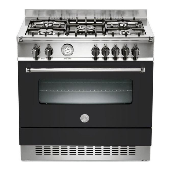
INSTALLATION, MAINTENANCE AND
BERTAZZONI RANGE COOKERS
Single Electric Ovens:
Double Electric Ovens:
READ THE INSTRUCTION BOOKLET BEFORE INSTALLING AND USING THE APPLIANCE.
The manufacturer will not be responsible for any damage to property or to persons caused by
The manufacturer is not responsible for any inaccuracies, due to printing or transcription errors,
contained in this booklet. In addition, the figures reported are purely indicative.
The manufacturer reserves the right to make changes to its products when considered necessary and
useful, without affecting the essential safety and operational characteristics.
USE INSTRUCTIONS
incorrect installation or improper use of the appliance.
A 90 5 MFE
AD 90 5 MFE
1
Advertisement
Table of Contents

Subscribe to Our Youtube Channel
Related Manuals for Bertazzoni A 90 5 MFE


Summary of Contents for Bertazzoni A 90 5 MFE
- Page 1 INSTALLATION, MAINTENANCE AND USE INSTRUCTIONS BERTAZZONI RANGE COOKERS Single Electric Ovens: A 90 5 MFE Double Electric Ovens: AD 90 5 MFE READ THE INSTRUCTION BOOKLET BEFORE INSTALLING AND USING THE APPLIANCE. The manufacturer will not be responsible for any damage to property or to persons caused by incorrect installation or improper use of the appliance. The manufacturer is not responsible for any inaccuracies, due to printing or transcription errors, ...
-
Page 2: Table Of Contents
These cookers are approved for use with Natural and Propane gases. Leave instructions with the owner. Important information Page Introducing your new cooker 4 Accessories 4 Before connecting your new cooker 4‐5 Safety considerations ... - Page 3 User instructions: Single electric ovens:‐ 15‐16 A90 5 MFE Double electric ovens:‐ 16‐18 AD 90 5 MFE Electric oven cooking tips 19 Oven cooking chart for electric ovens ...
-
Page 4: Introducing Your New Cooker
Introducing your new cooker Thank you for choosing a Bertazzoni. These instructions cover the range cooker models from the Professional and Heritage series which are available in the UK (Model numbers: AD 90 5 MFE; A90 5 MFE). These carefully designed products, are manufactured with the highest quality materials, and have been carefully tested to satisfy all your cooking demands. We therefore request that you read and follow these easy instructions which will allow you to obtain excellent results right from the start. The cooker’s rating plate is positioned on the rear of the cooker. There is also a copy of this attached to the front of this instruction manual. Always quote the rating plate details to identify the appliance when ordering spare parts or requesting a service. Note: Pictures and graphics in this manual cover the models mentioned above and may vary in minor details from your cooker. Accessories 1 universal grill pan with wire grid 2 wire shelves Your new cooker is protected by suitable packaging while it was on its way to you. Please make a contribution to protecting the environment by disposing of the packaging appropriately. Before disposing of the packaging, please ensure that all components have been removed. Before connecting your new cooker Before using your new cooker, please read these Instructions carefully. They contain important information concerning your personal safety as well as on use and care of the cooker. Please keep the operating and installation instructions in a safe place; this important documentation may also be of use to a possible subsequent owner. ... -
Page 5: Safety Considerations
Our appliances meet the applicable safety regulations for electrical appliances. Repairs may be performed only by an authorized service person. Inexpert repairs may entail serious injury to you, the user. Safety considerations Range cookers are heavy and should be handled by two people. Never lift or drag a range cooker by the oven handles as damage may occur. Never leave the appliance unattended when cooking with fat or oil. It could ignite if overheated. In case of a defect, switch off at the mains. Do not clean the oven with steam or high pressure cleaners. Ensure that the power cord does not get caught in the hot oven door. The plastic insulation could melt. Do not use loose grease proof paper in the oven (e.g. when heating the oven). The paper could be drawn to the fan and damage the fan and the element. Do not insert a baking sheet or aluminium foil sheet at the bottom of the oven. A heat build‐up could result and cooking times and temperatures could change or enamel could be damaged. Do not pour water on the hot oven floor. Damage to enamel could result. Always place a baking tray below a roast to prevent juices from dripping on the oven lining. Do not place heavy items on the oven door when open as this may result in damage to the door hinges. To ensure correct cooking the oven door must close properly. Keep the door sealing surfaces clean at all times. ... -
Page 6: Installing Your Dual Fuel Range Cooker
Installing a dual fuel range cooker Rating of Services The rating plate is visible at the rear of the cooker and a copy is also attached to the front of the manual. Before connecting the cooker, check that the requirements on the rating plate correspond with ... -
Page 7: Adaptation To Different Types Of Gas
Adaptation to different types of gas Before performing any maintenance operation, disconnect the appliance from the gas supply and electricity network. Replacing the nozzles to operate with another type of gas: Follow the instructions below to change the burner nozzles on the work surface: Pull out the plug from the electric outlet to avoid any type of electric contact. Remove the grids from the work surface. Remove the burners. Unscrew the nozzles using a 7 mm spanner, and replace them (fig. 1) with those needed for the new type of gas according to what is indicated in table below. fig.1 WARNING: After completing the above‐mentioned replacements, the technician must adjust the burners, as described in the paragraph below, seal any adjustment and pre‐adjustment devices and apply the label on the appliance, to replace the existing one, corresponding to the new gas adjustment. This label is contained in the spare nozzle bag. ... -
Page 8: Burner Adjustments
Burner Types of Press Nozzle Rater Capacity Reduced by‐pass Gas ure Diameter Capacity Diameter mbar 1/100 mm. g/h l/h kw kcal/ kw kcal/ 1/100 h h mm. Auxiliary Natural 20 77 ‐ 95 1 860 0,48 413 34 reg. G20 Propane 37 ... -
Page 9: Test Operation
Fig.2 fig.3 WARNING: The above‐mentioned adjustment should be made only with methane gas burners, while for those operating with liquid gas the screw must be locked at the end in a clockwise direction. The grill burner always operates at maximum and therefore no minimum adjustment is required. Test the operation of the cooker before leaving It should be noted that we cannot accept any liability for direct or indirect damage caused by incorrect connection or improper installation. When being repaired, the appliance must always be disconnected from the mains supply; if required, notify our customer service. Make sure the minimum clearances to combustible materials are maintained during the installation including adequate space for the operation and servicing of the cooker. Support legs 4 support legs are supplied separately and are fitted on location to the four corners of the lower support frame. After unpacking the cooker, lift it approx 250mm to fit the legs then gently lower the cooker to keep undue strain from the legs. It is recommended to use a lifting device instead of tilting the unit. Transit supports are left in situ. Each leg is firmly pushed over one of the transit supports. If the legs are not used and the cooker is mounted onto a plinth, leave transit legs in position to allow for clearance. ... -
Page 10: Anti-Tilt Restraint
Anti‐tilt restraint Once legs are adjusted to the correct height, fit the anti‐tilt restraint brackets. The anti‐tilt brackets must be fixed to the rear wall as shown below. 1. To calculate the position of brackets up from the floor, measure to the bottom of the anti‐tilt bracket location slots on the back of the cooker and add 32mm. 2. Secure the bracket in position on the rear wall with suitable insert. (Note that bracket are fixed 60mm in from the side edge of the cooker). 3. Slide the cooker against the rear wall until the brackets are fully inserted into the rear side of the cooker. Up‐stand Installation The up‐stand is packaged at the bottom rear of the cooker. The up‐stand is fixed along the rear of the cooker hob. Fixing points for locating the up‐stand are at either end and in the centre of the hob. 1. Remove the rear panel of the up‐stand by unscrewing 2 screws either side of the side brackets. 2. Place the front panels of the up‐stand on the rear of the hob, line up locating holes and fix from underneath with screws supplied on either side of the hob as indicated on the drawing. 3. Fix the centre 2 retaining screws from above the hob as indicated on drawing. and front panel of the up‐stand. 4. Reassemble the rear ... -
Page 11: Using Your Range Cooker
Important before leaving Instruct the owner in the use of the cooker. Using your range cooker First Time use ‐ Gas Hob Thoroughly clean hob with warm soapy water prior to first use to ensure all traces of manufacturing are removed. The individual burner position on the hob is indicated by a graphic placed above the burner control knob. Two further graphics indicated the ‘full on’ and ‘turn down positions. Ignition 1. To operate the individual hob burners depress the appropriate control knob and turn anti‐clockwise to the spark symbol. Push to activate the electronic ignition. 2. Once the flame is established turn the control knob to the desired setting. Keep the knob depressed for 10 seconds to activate the flame failure device. 3. If the flame goes out repeat the procedure. Hob burner adjustments. The control knob is used to adjust the flame of the gas burner. ‘High flame’ graphic = highest output ‘Low flame’ graphic = lowest output. Use ‘High flame’ setting to bring the pan to the boil, then adjust the flame to maintain the required pan temperature. Burner flames should be clear blue, with no yellow tipping. If the burners show any abnormality check that the burner heads are correctly located. If satisfactory performance cannot be obtained, contact Britannia Living. For service contact number refer page 5. Please state the cooker model number on the rating plate which is located on rating plate. Wok burner operation The wok burner consists of an inner small burner and an outer ring burner. The burners are controlled by two individual control knobs and can operate independently. Hob burner operation For safety and economic gas usage you should always use the correct pan on the correct burner. Flames should not protrude beyond the base of the pan. You will save energy, time and money by always placing the correct pan size on the correct gas ring. ... -
Page 12: Ventilation
Auxiliary burner (small) 12‐14cm diameter pan Semi‐rapid burner (medium) 14‐26cm diameter pan Rapid burner (large) 18‐26cm diameter pan Dual wok burner (wok) 22‐26cm diameter pan Ventilation The use of gas burners leads to the production of heat and moisture in the kitchen. For this reason make sure that the room is properly ventilated. Keep ventilation openings, such as windows, open or provide a mechanical ventilation device (e.g. an extractor hood or overhead exhaust fan). First time use – Oven 1. Thoroughly clean the oven and accessories with warm soapy water prior to first use to ensure all traces of manufacturing are removed. 2. Operate the oven for 30 minutes at 250°C to eliminate any odours generated by the internal insulation. Cooling fan operation The cooling fan operates when the oven is switched on and will continue to operate until the oven is switched off. Shelf positions These oven are fitted with 5 levels of shelf supports. The levels are counted from top to bottom. For best results when baking, with or without the fan operating, refer to the cooking charts on pages 20‐21. ... -
Page 13: Fan Assisted Operation
All shelf positions are suitable for multi‐level cooking in electric or gas fan assisted mode. Fan assisted operation The circulating fan can be activated from the function control knob for both the dual energy oven and the electric multi‐function oven. Activating the circulation fan, allows for fan forced oven cooking or fan assisted grilling. In this mode the oven interior maintains an even temperature at all shelf levels and negates the need for a separate rotisserie function. Function selector control The oven and grill functions are both contained within the one oven compartment, and can be used in conventional mode or with the fan for fan assisted mode. The functions are as follows: Icon Function Description Oven light The oven light will be activated on all other cooking functions and remain on during cooking Conventional Thermostat setting from 50° ‐ 250°C. cooking Moderate oven 180°C. In this mode heat is provided from the upper and lower heating elements. Cooking is possible on one shelf position only and food should be placed towards the centre of oven shelf position 2 or 3. ... - Page 14 True Fan Thermostat setting from 50‐250°C. mode. Moderate oven: 170°C. Rear circular element & fan. In this mode the rear element provides heat whilst the fan distributes the heat evenly throughout the oven interior. It is possible to cook several dishes simultaneously on different shelves and food can be placed on any shelf position. Meat cooked in a true fan mode, when elevated on the wire grid over the universal pan, will brown on all sides eliminating the need for a separate rotisserie function. It is particularly suitable for roasting cuts ...
-
Page 15: A90 5 Mfe
MODELS: SINGLE ELECTRIC OVEN A90 5 MFE These multi‐function ovens are designed to operate on electricity and equipped with an electric thermostat and a function selector. The function selector controls the elements relative to the graphic symbol on the control panel. In order to operate the oven or the grill both the electric thermostat and the function selector must be activated. Turning only one control knob will not have any effect on the oven except to turn on the oven light or the electric fan. The thermostat controls the oven at settings up to 250°C. The oven is heated by 4 elements; one on the floor of the oven, two against the roof of the oven and one circular element around the fan. The orange thermostat indicator light illuminates ... -
Page 16: Double Electric Ovens
be activated. Turning only one control knob will not have any effect on the grill except to turn on the oven light or the electric fan. 1. Turn the function selector control knob to the desired function. 2. Turn the electric thermostat control knob to the required temperature setting. The elements cycle ON and OFF as required to reach and maintain the set temperature. The orange thermostat indicator light illuminates ON and OFF to indicate that the element is activated. 3. Pre‐heat for 5‐10min. 4. Lightly oil meat or fish and place on wire grid over the grill pan. 5. Turn food only once during grill operation to conserve natural juices. The oven door must be closed during grilling. When the grill is used in the ‘fan assisted’ mode, set the thermostat no higher than 175°C, which is between the 150°C and 200°C settings, to avoid overheating the front of the appliance. To turn the grill off, return both the thermostat and the function selector control knobs the OFF position. ... - Page 17 of food. Personal experience will help determine any variations in the values reported in the table. In any case, it is recommended to follow the instructions of the particular recipe used. Oven operation 1. Turn the thermostat control knob to the required cooking temperature. The selected temperature will be maintained automatically. 2. Turn the function selector control knob to the required function. The elements cycle ON and OFF as required to reach and maintain the set temperature. When pre‐heating, the orange thermostat indicator light will go out when the required temperature has been reached. During cooking, the light will illuminate ON and OFF to indicate that the element is activated. To turn the oven off, return both the thermostat and the function selector control knobs the OFF position. Grill operation ...
- Page 18 The conventional right hand oven The function and temperature are controlled by one combined control knob. The oven is heated by 2 elements, one on the floor of the oven and one against the roof of the oven. The thermostat controls the conventional oven mode (top and bottom elements together) at settings from 50°C up to 250°C. When the bottom element, the top element or the grill modes are used, the temperature automatically sets at 250°C. The orange thermostat indicator light illuminates when the elements are activated. The elements cycle on and off as required to reach and maintain the set temperature. The thermostat indicator light goes out when the required temperature has been reached. ...
-
Page 19: Electric Oven Cooking Tips
Electric oven cooking tips Before cooking commences allow the interior to come up to the required temperature. (On electric ovens pre‐heat until the temperature indicating light extinguishes). Refer to cooking chart on pages 20‐ 21 for approximate cooking temperatures, times and tray positions. Personal experience will help determine any variations in the values reported in the table. In any case, it is recommended to follow the instructions of the specific recipe used. Open the door as little as possible during cooking. If it is necessary to open the door turn to a non‐fan function to minimise heat loss. Open the door as little as possible during operation. If necessary to cover food with foil or baking paper whilst cooking in fan mode, ensure that the foil or paper is firmly secured. For easy viewing and a more even cooking result bring the dishes and trays forward to the front of the oven shelf. Avoid placing food too close to the rear of the oven. For even heat circulation ensure that dishes and trays do not touch each other or the sides of the oven. Best results when baking, roasting and multi level cooking will be obtained by cooking with the fan in operation. ... -
Page 20: Oven Cooking Chart For Electric Ovens
Oven cooking chart for electric ovens Function Recommended shelf Any Shelves Shelves 2 Shelf 3 Shelves Shelves Any position shelf 2, 3 or 4 or 3 2 or 3 4 or 5 shelf Type of cooking √ √ Roast lamb, beef, ... - Page 21 Thermostat Shelf Approx. cooking time and comment setting position Biscuits Shortbread – whole, round 160°C 2 45‐60 mins depending on thickness biscuits 160°C 2 25‐‐35 mins Butter biscuits 170°C 2 1 or 2 trays side by side 15‐‐20 mins 170°C 2 4 trays 20‐‐25 mins (fan assisted only) Choc‐chip biscuits 180°C 2 1 or 2 trays side by side 15‐‐20 mins 180°C 2 4 trays 20‐‐25 mins (fan assisted only) Muffins ...
- Page 22 Bread Loaves ‐ up to 6 200°C 2 or 3 40‐‐50 mins Pizza Raw base 220°C 3 or 4 20‐‐25 mins Pre‐cooked 220°C 3 or 4 10‐‐15 mins ‐ if topping is very thick, turn on grill at end for 1‐‐2 mins Meringues Pavlova ‐ 4 egg whites 100°C 1‐‐1.25 hrs. NO FAN Meringues 100°C 2 45‐‐50 mins. NO FAN Roasting Medium size 180°C 3 ...
-
Page 23: Trouble Shooting
Trouble shooting guide PROBLEM POSSIBLE CAUSE ACTION Food taking too long to cook Opening oven door too Avoid opening door and minimise frequently or for too long time open Oven not pre‐heated sufficiently Allow to pre‐heat, especially for high temperature cooking Temperature set too low Check chart and /or raise temperature Food was chilled or partially Allow to thaw completely or allow frozen longer time for cooking Heat loss from oven Phone service number for service or advice Thermostat too low‐ faulty Phone service number for service or advice Food is cooking unevenly Tray or pan pushed too far to Allow 5 cm airflow all around the back or sides of oven Tray too large ... -
Page 24: Oven Interior
The high temperatures generated by using the wok burner may cause the stainless steel hob to become discoloured over time. THIS IS NORMAL. Clean the hob with a product suitable for cleaning stainless steel. Never use abrasive products, sharp objects, steel scouring pads, knives, etc., to remove stubborn food remains from the hob surface, trivets, burners and oven interior. Do not allow acidic products such as vinegar, lemon juice, etc., to come into contact with the hob. Cleaning oven interior Clean the oven enamelled floor, wire shelves and shelf supports with hot detergent suds. Important: always clean the enamelled surfaces and wire components prior to starting the 30 minute heat cleaning cycle. It is recommended that the oven interior be cleaned regularly as excessive build‐up of fat can become a fire hazard. Cleaning oven shelf supports To remove the shelf supports remove the knurled knobs either side, lift the wire rack and swing forwards. Cleaning oven glass door The oven door may be removed for cleaning. To remove the oven door follow the steps below: 1. Open the door fully. 2. Into each hinge insert a 4mm Ø pin as indicated in drawing. (Pins not supplied). Ensure that the pin is fully inserted through the hinge layers and protrudes out the other side. 3. Close the door approx. 30° from horizontal and lift outwards to remove it from its mounting slots. Leave pins inserted. 4. To replace the door, fit the hinges into their mounting slots and lower the door to horizontal. 5. Remove the pins. 6. Close the door. Use a window cleaner to clean the exterior glass panel. ... -
Page 25: Replacing Oven Light
Replacing the oven light Type: E14, 25W, heat resistant to 300°C. You may obtain this bulb from our service department as mentioned on page 5 1. Disconnect the appliance from the main electricity supply. 2. To prevent damage place a tea cloth in the bottom of the oven. 3. Unscrew the glass cover of the light. 4. Unscrew the old light bulb and replace it with a new one. 5. Replace cover. 6. Reconnect the power supply. 32 ... - Page 26 ...
- Page 27 ...
- Page 28 ...
Need help?
Do you have a question about the A 90 5 MFE and is the answer not in the manual?
Questions and answers