Table of Contents
Advertisement
Quick Links
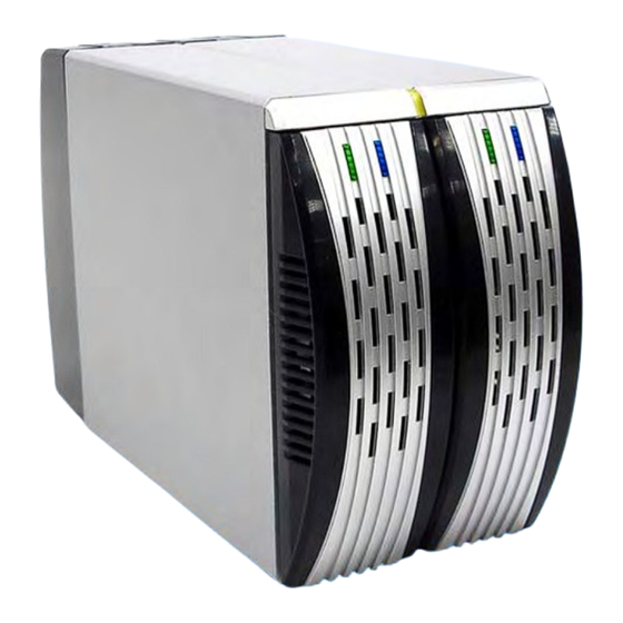
3.5" SATA HDD 2-BAY RAID SYSTEM
Easy Storage Management for High Productivity
User's Manual
The product information provided in this manual is subject to change without prior notice and
does not represent a commitment on the part of the vendor. The vendor assumes no liability or
responsibility for any errors that may appear in this manual
Copyright 2007, Onnto Corporation. All rights reserved.
Web version 03
Advertisement
Table of Contents

Summary of Contents for DataWhale RS-M2TS
- Page 1 3.5” SATA HDD 2-BAY RAID SYSTEM Easy Storage Management for High Productivity User’s Manual The product information provided in this manual is subject to change without prior notice and does not represent a commitment on the part of the vendor. The vendor assumes no liability or responsibility for any errors that may appear in this manual Copyright 2007, Onnto Corporation.
-
Page 2: Table Of Contents
3.5” SATA HDD 2-BAY RAID SYSTEM User’s Manual Introduction ....................... 3 Features ......................3 Important Reminders for the RAID System ..........4 Getting Started....................5 System Requirements................... 5 Package Contents..................5 2-BAY RAID SYSTEM Views by Model ............7 Front View - All Models ................. 7 Top Rear View –... -
Page 3: Introduction
Introduction Thank you for purchasing the 3.5” SATA HDD 2-bay RAID System. The 2-bay RAID System provides massive storage capacity and advanced RAID configuration options in a desktop storage device. The Mode switch allows easy configuration of Striping (RAID 0), Spanning, Mirroring (RAID 1) and JBOD RAID Modes. Features •... -
Page 4: Important Reminders For The Raid System
Important Reminders for the RAID System The main circuit board of the RAID System is susceptible to static electricity. Proper grounding is required to prevent electrical damage to the RAID System or other connected devices, including the computer host. Always place the RAID System on a smooth surface and avoid all dramatic movement, vibration and percussion. -
Page 5: Getting Started
Getting Started The installation instructions in this manual apply to the following models. • USB 2.0 2-bay RAID System • eSATA/USB 2.0 2-bay RAID System • USB 2.0/FireWire 800 2-bay RAID System • eSATA/USB 2.0 2-bay RAID System with eSATA PCI Express Card System Requirements •... - Page 6 Optional Accessories for eSATA/USB 2.0 2-bay RAID System with eSATA PCI Express Card • eSATA PCI Express Card • Installation CD USB 2.0/FireWire 800 model • 2-bay RAID System • USB A to mini B Cable • IEEE 1394b Cable •...
-
Page 7: 2-Bay Raid System Views By Model
2-BAY RAID SYSTEM Views by Model Front View - All Models System LED Indicator HDD LED Indicator HDD Trays... -
Page 8: Top Rear View - All Models
Top Rear View – All Models Quick HDD release levers... -
Page 9: Rear View - Usb 2.0 Model
Rear View – USB 2.0 Model Mode Switch Power Switch Reset Button USB mini-B Port DC IN 10) Fan 11) Lock Port... -
Page 10: Rear View - Esata/Usb 2.0 Model
Rear View – eSATA/USB 2.0 Model Mode Switch Power Switch Reset Button USB Type B Port eSATA Port 10) DC IN 11) Fan 12) Lock Port... -
Page 11: Rear View - Usb 2.0/Firewire 800 Model
Rear View – USB 2.0/FireWire 800 Model Mode Switch Power Switch Reset Button USB Port FireWire 800 Ports 10) DC IN 11) Fan 12) Lock Port... -
Page 12: Installing/Replacing The Hard Drives In The Raid System
Installing/Replacing the Hard Drives in the RAID System Install an HDD by completing the following steps. After installing the HDD, install required software if any. Lift the quick HDD release lever to release the selected HDD tray from the desired drive bay. Slide the HDD tray out of the drive bay. - Page 13 all. If this occurs, carefully slide the HDD tray out of the drive bay after lifting the quick HDD release lever. When removed the HDD tray appears as shown below. Carefully slide the HDD into the drive tray.
- Page 14 Ensure that the interface connectors are oriented toward the rear of the drive tray. Data & power connectors are on this side. Locate the screws included in the package. Ensure that the screw guides on the side of the HDD are aligned with the openings on the side of the drive tray. Fasten the HDD to the drive tray by inserting and tightening the screws.
- Page 15 Align the drive tray with the guide rails and slide it into the drive bay. Ensure that the tray is completely inserted and that the interface connectors are properly seated. The RAID System is ready for connection to a host.
-
Page 16: Connecting The Raid System To A Computer
Connecting the RAID System to a Computer Complete the following steps to connect the enclosure to a host computer. Connect the AC/DC power adapter. Insert the connector of the eSATA, USB 2.0, or FireWire 800 cable into the corresponding port of the RAID System. - Page 17 Insert the connector of the eSATA, USB 2.0 or FireWire 800 cable into the corresponding port of a host computer. Computer Note: Due to compatibility issues, the Silicon Image eSATA host controller is highly recommended for the eSATA/USB 2.0 model. Turn the power switch to the on position.
-
Page 18: Safe Removal Of The Raid System
When connected the System LED lights steadily orange. Note: The RAID System should only be connected to a host computer via one interface. Connection of the system to a computer via two or more interfaces simultaneously is not recommended. You are now ready to begin using your RAID System. Safe Removal of the RAID System eSATA/USB 2.0 model The host, depending on the eSATA controller, may handle external eSATA HDD... -
Page 19: Setting The Raid Mode
Setting the RAID Mode Deleting the current partition prior to changing RAID modes is highly recommended. eSATA/USB 2.0 model Due to the chipset of the eSATA/USB 2.0 model, after deleting the current partition and setting the new RAID mode, the reset button on the right side of the Mode switch must be pressed in order for the updated RAID mode to take effect. - Page 20 USB 2.0/FireWire 800 RAID Modes Note on Setting the RAID Mode Changing the RAID Mode deletes all data stored on the device. If you have saved data in the drives, backup all data before changing the RAID Mode.
-
Page 21: Led Indicators
LED Indicators The LED indicators vary by model. eSATA/USB 2.0 Model System Orange Green Blue Green Blue System LED x 1 (Orange) Indicators Orange Power on Power off HDD LED x 2 (Green, Blue) Indicators RAID Mode Green Blue Disk error Stripe, Span, Mirror Blink Blink... -
Page 22: Usb 2.0 And Usb 2.0/Firewire 800 Model
USB 2.0 and USB 2.0/FireWire 800 Model System Orange Blue Blue System LED x 1 (Orange) Indicators Orange Power on Power off HDD LED x 2 (Red, Blue) Indicators RAID Mode Blue Disk error Stripe, Span, Mirror, JBOD Data access Stripe, Span, Mirror, Flash JBOD... -
Page 23: Rebuild And Hot Swap Functions
Rebuild and Hot Swap Functions Rebuild In Mirror mode, if one of the HDDs fails and is replaced with a functional HDD, the RAID System will automatically rebuild the target HDD (the new functional HDD) with data from the source HDD (the remaining functional HDD) sector by sector. After the rebuild is complete, data in both HDDs will be identical. -
Page 24: Hot Swap
Hot Swap Hot Swap refers to the ability to add or remove a device from the host computer without first powering off the device. After adding or removing the device, the operating system automatically recognizes the change. Due to the chipset, hot swap support varies by RAID System model. -
Page 25: Raid System And Raid Modes
RAID System and RAID Modes A Redundant Array of Independent (or Inexpensive) Disks (RAID) is a system that utilizes multiple hard drives to share or replicate data among the disks. The benefit, depending on the selected RAID Mode (combinations of disks), is one or more of increased data integrity, fault-tolerance, throughput or capacity when compared to single drives. -
Page 26: Spanning
Spanning Spanning provides another maximum capacity solution. Spanning combines multiple hard drives into a single logical unit. Unlike Striping, Spanning writes data to the first physical drive until it reaches full capacity. When the first disk reaches full capacity, data is written to the second physical disk. Spanning provides the maximum possible storage capacity but does not increase performance. -
Page 27: Jbod
Mirroring offers the highest level of data protection. If one disk in the array fails, a backup is always available. Mirroring is typically used in mission-critical systems, such as payroll, accounting, and ERP databases. JBOD Just a Bunch of Disks (JBOD) refers to a group of hard drives. In JBOD, the number of logical drives is equal to the number of physical drives. -
Page 28: Esata Pci Express Card Installation
eSATA PCI Express Card Installation Complete the steps provided in this section to install the eSATA PCI Express Card for use with the eSATA/USB 2.0 RAID System. The eSATA PCI Express Card provides a host computer with two Windows and Mac compatible eSATA ports. System Requirements •... -
Page 29: Driver Installation
Driver Installation In Windows systems the “Add New Hardware Wizard” will open automatically, insert the installation CD included in the package, navigate to and open the installation file. Follow the provided prompts to complete the driver installation. For Mac OS, insert the installation CD and locate the Mac driver installation file. - Page 30 Mac OS If a driver installation failure error message appears after restarting the computer, follow the recommendations provided in the error message. Note: Please refer to more driver installation step by step at our website, or in the installation CD.
-
Page 31: Notices And Classifications
Notices and Classifications FCC-B Radio Frequency Interference Statement This device complies with part 15 of the FCC rules. Operation is subject to the following two conditions: This device may not cause harmful interference. This device must accept any interference received, including interference that may cause undesired operation.
Need help?
Do you have a question about the RS-M2TS and is the answer not in the manual?
Questions and answers