
Related Manuals for Remotec ZXT-310


Summary of Contents for Remotec ZXT-310
- Page 1 ZXT-310 (Z-Wave-to-AV IR Extender) Firmware Version: V1.0, V1.1, V1.2...
-
Page 2: Table Of Contents
........15 End-Point Selection Control ......16 Wave Configuration Parameters ..... 17 Installation ............. 21 Mounting the ZXT-310 to a wall ......21 Wireless Information........23 Maintenance ........... 23 Frequently Asked Questions ......23 Technical Specifications ........25 Checking Accessories ........26 FCC Notice ............ -
Page 3: Introduction
ZXT-310 (Z-Wave-to-AV IR Extender) Operating Instructions Introduction ZXT‐310 is a Z‐Wave‐to‐AV IR Extender (Figure 1) and it works with any Z‐Wave compliant controller or gateway by translating Z‐Wave Simple AV command to IR control code. User can set the IR code from the built‐in code library of ZXT‐310, or use the learning function of ZXT‐310 through any Z‐Wave controller or gateway. Figure 1. Operation diagram It also supports Z‐Wave networks with multiple gateways and controllers. Like every Z‐Wave accessory, the user will need to include the ZXT‐310 into his Z‐Wave network using the primary controller. Then, the user can use either the primary controller or secondary controller to configure and setup the ZXT‐310 using Z‐Wave’s configuration command class. Once the configuration and setup is completed, the controller can use Z‐Wave’s “Simple AV commands class” to control their IR‐controlled AV equipment with the ZXT‐310. User can enjoy fully wireless control and home automation system anywhere at home. ... -
Page 4: Controller And Gateway Requirements
Controller and Gateway Requirements The ZXT‐310 is architected to work with any Z‐Wave compliant controller or gateway supporting the following Z‐Wave commands. Configuration Command Class Simple AV Command Class Multi‐channel Command Class (optional) Built‐in IR code library The built‐in IR code library enables the ZXT‐310 to work with any Z‐ Wave compliant gateway and controller. Gateway and controller will not need to have any knowledge related to IR control code. It also eliminates the need for complex set up procedures and proprietary Z‐ Wave commands to configure the system. The IR code library supports various brand name of AV equipment found in the today’s market. User can use his controller or gateway to send a 4 digits AV IR code number (include the brand selection) using standard Z‐Wave configuration command. Host based IR code library ZXT‐310 also supports host‐based library upgrade for 6 AV database. Once gateway support this advanced feature, 6 AV database can be upgraded by gateway very easily and support different regions and customers. ... -
Page 5: Glossary
Glossary Devices and nodes are all terms to describe an individual Z‐Wave device. These are all Device or Node interchangeable when setting up your Z‐ Wave network. Inclusion Add a Z‐Wave device to the network. Exclusion Delete a Z‐Wave device from the network. To take a device out of a group, scene or Remove association group while that device still exists in the same Z‐Wave network. A collection of Z‐Wave devices is controlled by primary and secondary controllers Z‐Wave operating on the same system. A Z‐Wave Network network has its own unique ID code so that controllers not in the network cannot control the system. The first controller is used to set up your devices and network. Only the Primary Controller can be used to include or delete Primary modules from a network. It is recommended Controller that you mark the primary controller for each network for ease in modifying your network. Network Wide Inclusion (NWI) enables both end‐user friendly, Plug and Play like Z‐Wave network installation as well as professional installation scenario where the inclusion Network Wide process in terms of time will be reduced Inclusion (NWI) significantly. NWI is a feature supported by a new frame type named Explorer which enables the Z‐Wave protocol to implement ... -
Page 6: Product Overview
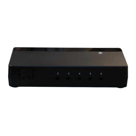
Indication IR Port 1 Learning Figure 2 PROG Key and IR Ports of ZXT-310 Setup and Operations Before using the ZXT‐310, please read the [INSTALLATION] if it is needed to mount the ZXT‐310 to a wall. Power up the ZXT‐310 by the supplied AC/DC adaptor. CAUTION − Be sure to always use the supplied AC/DC adaptor. − Do not try to power up other device with the supplied AC/DC adaptor. This could damage the AC/DC adaptor or the connected device. (Please carefully read through the following then store the manual for ... -
Page 7: Include / Exclude Device To Network
Note 1: Red LED flashes 6 times means the setup process is failed. Please redo the process again. Note 2: If you can’t add the ZXT-310 to network, it might have been included in another Z-Wave network or the ZXT-310 is not on Channel 1 (EP1). - Page 8 Deleting Device from the Network LED Indication Step Setup Key Status on ZXT‐310 • LED flashes Make sure ZXT‐310 switched to 1 Channel 1 (EP1) once then keep on Refer to your primary controller ‐ 2 instructions to process the exclusion setup procedure. • LED flashes Press the PROG button on ZXT‐310 twice then keep on 3 • Device exclusion completed ...
-
Page 9: Add/Remove Device To/From A Simple Av Channel
Figure 3. Z-Wave-to-IR Channel (EP) and IR Ports Device End‐point IR code IR output IR output no. no. port no. power Device icon 1 Device icon 2 Device icon 3 Device icon 4 Device icon 5 Device icon 6 Configuration data in ZXT-310... -
Page 10: Ir Code Selection
IR Code Selection Selecting an IR Device Code in ZXT‐310 Important − Please make sure that the “End point selection control” has completed (if necessary) before process the following setup. LED Indication Step Setup Key Status on ZXT‐310 • LED flashes Make sure ZXT‐310 switched to 1 Channel 1 (EP1) once then keep on Refer to your primary controller ‐ instructions to process the configuration setup procedure. 2 ‐ Parameter: 27 ‐ Value: 0001 (Refer to IR code list of ZXT‐310) • LED flashes Press the PROG button on ZXT‐310 ... -
Page 11: Ir Port Mapping
IR Port Mapping Mapping individual Channel to individual Port in ZXT‐310 Important − Please make sure that the “End point selection control” has completed (if necessary) before process the following setup. LED Indication Step Setup Key Status on ZXT‐310 • LED flashes Make sure ZXT‐310 switched to 1 Channel 1 (EP1) once then keep on Refer to your primary controller ‐ instructions to process the configuration setup procedure. 2 ‐ Parameter: 29 ‐ Value: 01 (Enter the IR port number 1 ‐6 which you want to transmit the IR signal) • LED flashes Press the PROG button on ... -
Page 12: Ir Output Power
IR Output Power Set IR Output Power Level for each IR port (except IR Port 1) Important − Please make sure that the “End point selection control” has completed (if necessary) before process the following setup. LED Indication Step Setup Key Status on ZXT‐310 • LED flashes Make sure ZXT‐310 switched to 1 Channel 1 (EP1) once then keep on Refer to your primary controller ‐ instructions to process the configuration setup procedure. ‐ Parameter: 28 (0x1C) ‐ Value: 255 (0xFF) 2 Set IR output power level by entering 0 (0x00) Normal power mode 255 (0xFF) High power mode ... -
Page 13: Ir Code Learning
IR Port Number IR Output Power Mode Default value 1 Un‐configurable ‐ 2 Configure as Normal or High High 3 Configure as Normal or High High 4 Configure as Normal or High High 5 Configure as Normal or High High 6 Configure as Normal or High High IR Port Output Power IR Code Learning Learning IR Code on ZXT‐310 (Learn an IR control code from the original remote control to ZXT‐310) Important − Please make sure that the “End point selection control” has completed (if necessary) before process the following setup. ... -
Page 14: Reset Zxt-310 To Factory Default
Please redo the process again. Note 2: On step 4, if no IR signal received for more than 15 seconds, the Error LED in front will flashes six times then all LED turn off, Learning on ZXT-310 mode will exit automatically. When you encounter problem, check followings: ... -
Page 15: Zxt-310 Information
ZXT‐310 Information How to get the NIF “Node Information Frame" on ZXT‐310 LED Indication Status on Step Setup Key ZXT‐310 • LED flashes Make sure ZXT‐310 switched to 1 Channel 1 (EP1) once then keep on • LED flashes Press the PROG button on the ZXT‐ 310 once then keep on (EP1 will response ”NIF” 2 (ZXT‐310 will EP2, EP3, EP4, EP5, EP6 will response report the “Multi‐channel capability report”) supported command class) IR Transmission Mode Set IR transmission mode for IR transmission LED Indication Step Setup Key Status on ZXT‐310 •... -
Page 16: End-Point Selection Control
successful Note 1: Red LED flashes 6 times means that the setup process is failed. Please redo the process again. End‐Point Selection Control Set target end point by configuration command class LED Indication Step Setup Key Status on ZXT‐310 • LED flashes Make sure ZXT‐310 switched to 1 Channel 1 (EP1) once then keep on Refer to your primary controller ‐ instructions to process the configuration setup procedure. ‐ Parameter: 38 (0x26) ... -
Page 17: Z Wave Configuration Parameters
Wave Configuration Parameters Parameter Size Definitions Parameter Value Number (Byte) 1—20 UIRD formatted raw data 4 Depends on IR (0x01— for the Simple AV code data 0x14) command number or key being downloaded or (Depend on UIRD uploaded data) 21 The Simple AV command 2 Referred to (0x15) number or key going to be Simple AV downloaded to the ZXT‐ command class 310 key ID (Default : 0x0000 No simple AV ID is selected) 22 Download status register 1 ... - Page 18 ZXT‐310 receive a get Command Full command to this 4 (0x04): Learning parameter Fail 27 IR code number for built‐in 2 Refer “Code list” (0x1B) code library for details 28 External IR Emitter power 1 0 (0x00): normal (0x1C) level power mode 255 (0xFF): high * If IR output port routing power mode is set to 1, IR transmission (default) power level cannot be changed 29 IR output port routing 1 1 (0x01): IR Port 1 (0x1D) (default) 2 (0x02): IR Port 2 3 (0x03): IR Port 3 4 (0x04): IR Port 4 5 (0x05): IR Port 5 6 (0x06): IR Port 6 30 ...
- Page 19 Mapping Information − BASIC Set Value 0x00 will map to Simple AV key ID (Power Off) 0x00F7. − BASIC set Value 0xFF will map to Simple AV key ID (Power) 0x0027. AV Command to IR Control Code (US, BR, CN) Mapping Table ...
- Page 20 AV Command to IR Control Code (EU, AU, IN, RU, IL) Mapping Table Information − If you are using Gateway or other z‐wave controllers to operate ZXT‐310, Please follow the instruction from the gateway or other controller. ...
-
Page 21: Installation
Installation Mounting the ZXT‐310 to a wall MOUNTING LOCATION PRECAUTIONS • Before mounting, check the material and structure of the mounting location. If the location does not have the proper material or structure, the ZXT‐310 can fall and cause an injury. • Use commercial items that best match the wall structure and material for the screws and other fixtures. • Do not mount near a kitchen counter, humidifier, or other location in which it can be exposed to smoke or steam. Doing so could cause a fire or electrical shock. • Do not mount in locations with high humidity or large amounts of dust. Doing so could cause a fire or electrical shock. • Do not mount to locations subject to high temperatures, high humidity, or exposed to water. Doing so could cause a fire or electrical shock. • Do not mount to locations subject to large amounts of vibration, large jolts, or large forces. These could cause an injury if the ZXT‐ 310 falls and breaks. MOUNTING PROCEDURE PRECAUTIONS • Do not modify parts or use the ZXT‐310 in ways other than its intended use. Doing so could cause the ZXT‐310 to fall and result in an injury. • Be sure to fully check that there are no electrical wires or pipes inside the wall before mounting. • If any of the screws are loose, the ZXT‐310 can fall and cause an injury. Do not mount the ZXT‐310 with the screws still loose. • Check that the two screws mounted to the wall are fully inserted into the key holes of the ZXT‐310. Otherwise, the ZXT‐310 can fall and cause an injury. ... - Page 22 Insert the ZXT‐310 key holes onto the two screws mounted to the wall, and then slide downward to secure in place. After securing the ZXT‐310 to the wall, connect the AC/DC adaptor and cables to the ZXT‐310. Note 1: Check that the ZXT-310 is firmly secured to the wall. Note 2: Insert the AC/DC adaptor and IR emitter cable so that they are firmly connected to the ZXT-310. When removing the ZXT‐310 from the wall, lift up the ZXT‐310, then pull it towards you. ...
-
Page 23: Wireless Information
Wireless Information This device has an open air line of sight transmission distance of 25m which complies with the Z‐Wave standards. Performance can vary depending on the amount of objects in between Z‐Wave devices such as walls and furniture. Every Z‐Wave device set up in your house will act as a signal repeater allowing devices to talk to each other and find alternate routes in the case of a reception dead spot. Radio frequency limitations: 1. Each wall or object (i.e.: refrigerator, bookshelf, large TV, etc) can reduce the maximum range of 20m by up to 20 to 30%. 2. Plasterboard and wooden walls block less of the radio signal then concrete, brick or tile walls which will have more of an effect on signal strength. 3. Wall mounted Z‐Wave devices will also suffer a loss of range as they are housed in metal junction boxes which could reduce the range by up to 20 to 30%. Maintenance Do not expose your unit to dust, strong sunlight, humidity, high temperatures or mechanical shocks. Do not use corrosive or abrasive cleansers on your unit. Keep the unit dust free by wiping it with a soft, dry cloth. Do not disassemble your unit; it contains no user‐serviceable parts. Frequently Asked Questions Q Why won’t my unit work with the Z‐Wave devices I purchased from another country? A Due to different countries regulations Z‐Wave products from different regions are set to different frequencies. Before purchasing new devices make sure you have checked to see that the device is compatible in your region. ... - Page 24 Z‐Wave Extender IR port output Z‐Wave wall switch / dimmer Multi-Channel Device Multi-Channel Device End Point 2 End Point 1 Z‐Wave power strip Multi-Channel Device End Point 1 Multi-Channel Device End Point 4 Please refer to the target device user manual for more information such as Inclusion / Exclusion and add End Point to a Scene / Group. ...
-
Page 25: Technical Specifications
ZXT‐310 supports two IR power levels for the external IR emitter to avoid saturation of the IR receiver. You can set the IR output power level by the Parameter Table value (normal or high power mode) or adjust the position of your external IR emitter. Q Can I use 2 or more ZXT‐310 in my house? What is the max. units if yes? A Yes and it is very depend on the capability of gateway / controller. For example, gateway can supports up to 1, 6 or more ZXT‐310 in a network. Technical Specifications BW8371US (ZXT‐310US) BW8371EU (ZXT‐310EU) BW8371AU (ZXT‐310AU) BW8371IN (ZXT‐310IN) Model No. BW8371RU (ZXT‐310RU) BW8371BR (ZXT‐310BR) BW8371IL (ZXT‐310IL) BW8371CN (ZXT‐310CN) 908.42MHz (ZXT‐310US) 868.42MHz (ZXT‐310EU) 921.42MHz (ZXT‐310AU) 865.22MHz (ZXT‐310IN) RF Frequency 869.02MHz (ZXT‐310RU) 921.42MHz (ZXT‐310BR) 916.02MHz (ZXT‐310IL) 868.42MHz (ZXT‐310CN) up to 80ft outdoor line of sight, in RF operating distance unobstructed environment up to 25ft line of sight, in IR operating distance unobstructed environment ... -
Page 26: Checking Accessories
Checking Accessories After opening the cover of the packing box, check that the following accessories are included. • ZXT‐310: Z‐Wave‐to‐AV IR Extender • Power adaptor: 100~240Vac input, 5Vdc 1000mA (for ZXT‐310) • IR Emitting Cable: 3.5mm Mono plug cable x 3pcs (for ZXT‐310) • User Manual (download from our website) • Code List (download from our website) • Warranty sheet FCC Notice This device complies with Part 15 of the FCC rules. Operation is subject to the following two conditions: (1) this device may not cause harmful interference, and (2) this device must accept any interference received, including interference that may cause undesired operation. NOTE: This equipment has been tested and found to comply with the limits for a Class B digital device, pursuant to Part 15 of the FCC Rules. These limits are designed to provide reasonable protection against harmful interference in a residential installation. This equipment generates, uses and can radiate radio frequency energy and, if not installed and used in accordance with the instructions, may cause harmful interference to radio communications. However, there is no guarantee that interference will not occur in a particular installation. If this equipment does cause harmful interference to radio or television reception, which can be determined by turning the equipment off and on, the user is encouraged to try to correct the interference by one or more of the following measures: ... -
Page 27: Warnings
Warnings Do not modify the unit in any way. Risk of fire. Risk of electrical shock. Risk of burns. Do not dispose of electrical appliances and unsorted municipal waste, use separate collection facilities. Contact your local government for information regarding the collection systems available. There is no user serviceable parts in this unit. The socket‐outlet shall be installed near the equipment and shall be easily accessible. Use only power supplies listed in the user instructions. Caution Risk of explosion if battery is replaced by an incorrect type. Dispose of used batteries according to the instructions. Printed in China F820‐8371‐0000...
Need help?
Do you have a question about the ZXT-310 and is the answer not in the manual?
Questions and answers