Champion UH-200B Technical Manual
Undercounter
Hide thumbs
Also See for UH-200B:
- Technical manual (175 pages) ,
- Installation and operation manual (106 pages) ,
- Installation & operation manual (106 pages)
Table of Contents
Advertisement
Quick Links
For machines beginning with Serial no. U-2239
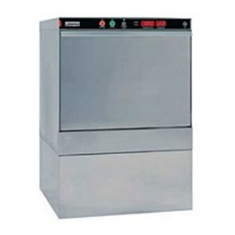
Model UH-200B Shown
June, 2001
P. O. Box 4149
Winston-Salem, North Carolina 27115-4149
336/661-1556
Fax: 336/661-1660
Champion Manual
www.championindustries.com
Technical Manual
Undercounter
Dishwasher
Model
UH-200B
High Temperature with Built-in Booster
Fresh Water Final Rinse
UH-200
High Temperature
Fresh Water Final Rinse
Machine Serial No.
113247
P/N
Jordan Station, Ontario, Canada L0R 1S0
905/562-4195
Rev. B
2674 N. Service Road
Fax: 905/562-4618
Advertisement
Table of Contents
Troubleshooting

Subscribe to Our Youtube Channel
Related Manuals for Champion UH-200B


Summary of Contents for Champion UH-200B
- Page 1 Dishwasher Model UH-200B High Temperature with Built-in Booster Fresh Water Final Rinse UH-200 High Temperature Fresh Water Final Rinse Model UH-200B Shown Machine Serial No. 113247 June, 2001 Champion Manual Rev. B P. O. Box 4149 2674 N. Service Road...
- Page 2 Note: When calling to order parts, be sure to have the model number, serial number, voltage and phase of your machine. Machine Data Plate with model & serial number Machine located on the front of the lower panel. COPYRIGHT © 2001 by Champion Industries, Inc. All Rights Reserved.
- Page 3 REVISION RECORD REVISION RECORD Revision Revised Serial Number Comments Date Pages Effectivity 9/18/00 U-2239 First issue of manual and replacement parts lists 4/3/01 — Removed UH100 rinse aid pump from drawing 5/1/01 U1938 Change touch pad P/N 112621 to 113292 and 900827...
-
Page 4: Safety Summary
• Your Champion dishwasher uses hot water to clean and sanitize a variety of wares. Machine surfaces and wares become hot during and immediately following normal operations. Operators should use caution when loading and unloading wares from the machine. -
Page 5: Limited Warranty
If a defect in workmanship or material is found to exist within the warranty period, Champion, at its election, will either repair or replace the defective machine or accept return of the machine for full credit; provided, how- ever, as to glasswashers, Champion's obligation with respect to labor associated with any repairs shall end (a) 120 days after shipment, or (b) 90 days after installation, whichever occurs first. -
Page 6: Table Of Contents
2.7.2 Model UH-200 ................... Electrical Connections (Three Phase) ..............2.8.1 Model UH-200B ..................Chemical Connections ..................2.9.1 General (All Models) ................. 2.9.2 Models UH-200B, UH-200 (Chemical Adjust and Prime) ......2.10 Installing Optional Chemical Pumps ..............2.10.1 Model UH-200B, UH-200 ............... 2.11 Initial Start-up (All Models) ................ - Page 7 Preparing your Dishwasher (All Models) ............Loading your Dishwasher (All Models) .............. Description of Operator Controls and Displays (All Models) ......Basic Operation ....................3.5.1 Model UH-200B, UH-200 ................. PART 4: CLEANING and MAINTENANCE ..........Introduction ......................Daily Cleaning Schedules (All Models) ..............
- Page 8 Electrical Component Locator Diagram ..........8.1.3 Troubleshooting the 10-point Terminal Board ........Components ......................8.2.1 Pressure Reducing Valve, (PRV), Adjustment ........Model UH-200B, UH-200 8.2.2 Water Line Strainer ................Model UH-200B, UH-200 8.2.3 Fill/Rinse Water Solenoid Valve ............Model UH-200B, UH-200 8.2.4...
- Page 9 Drain Pump/Motor, Drain Valve (All Models) ..........8.2.12 Wash Arm Bearings (All Models) ..............8.2.13 Rinse Arm Bearings .................... Model UH-200B, UH-200 8.2.14 Door Shock and Hinge Assembly (All Models) ..........8.2.15 Door Safety Switch and Magnet (All Models) ...........
- Page 10 2.9.3 – Chemical Bottle Placement ..............Figure 2.9.4 – UH-200B, UH-200 Touchpad/Display ........... Figure 2.9.5 – Rinse Aid Injection Point (UH-200B, UH-200) ........Figure 2.10.1 – UH-200B, UH-200 Chemical Pumps ............ Figure 2.10.2 – Chemical Pump Connection Terminal Block .........
- Page 11 LIST OF FIGURES (Cont.) Figure 9.1 – Upper Hood Assembly and Control Cabinet (All Models) ......Figure 9.2 – Tank, Base, Guide Rails, and Panels (UH-200B, UH-200) ......Figure 9.4 – Door and Door Safety Switch Assembly (All Models) ....... Figure 9.5 –...
-
Page 12: Part 1: General Specifications
All information, illustrations and specifications contained in this manual are based upon the latest product information available at the time of publication. Champion constantly improves its products and reserves the right to make changes at any time or to change specifications or design without notice and without incurring any obligation. -
Page 13: Model Numbers
140°F/60°C. A (70°F/39°C) rise booster is available which requires a minimum incoming water supply temperature of 110°F/43°C. The UH-200B is a fresh water rinse machine. Final rinse water enters the final rinse spray system under line pressure. A portion of the final rinse water is retained for the next wash cycle. -
Page 14: Standard Equipment
Pumped drain ♦ Flexible fill and drain hoses ♦ Door safety switch ♦ Easily removable scrap screen ♦ Dishracks (peg rack and flat bottom rack) UH-200B UH-200 ♦ ♦ 40°F/22°C rise booster Tank heater ♦ ♦ Tank heater Low water tank heat protection ♦... -
Page 15: Dimensions, Capacities, And Rough-In
Volume crated: 15 cu. ft. [.4 cu.m] Approx. Shipping UH-200B, UH-200 30 racks/hr. weight crated: 215 lbs [98 Kg] Wash Tank Capacities UH-200B, UH-200 ≅ 3.6 US gal. (14 liters) Water Usage (per rack) UH-200B, UH-200 1.1 US gal. (4.2 liters) " [607]... - Page 16 Part 1: GENERAL SPECIFICATIONS 1.4 Dimensions and Capacities, and Rough-in 3" [76] 23" Wall [584] Clearance Model UH-200B " [375] Model UH-200 Clearance 4" [858] " " [362] [42] SIDE VIEW Electric WARNING: Water Refer to Part 2: Installation, Sections 2.1 through 2.9, before connecting the dishwasher to utilities.
-
Page 17: Part 2: Installation
• Upper and lower spray arm assemblies • Round scrap screen • Rubber pads for leveling feet (set of 4) • 3/4" line strainer (P/N 110768) (Model UH-200B, UH-200 Only) • Warranty information packet 4. Remove the dishwasher from the skid. -
Page 18: Permanent Placement
Part 2: INSTALLATION 2.3 Permanent Placement Special Tools — • Bubble level (3 ft.) Perform the following steps to place the dishwasher in its permanent location. Refer to the machine diagrams in Section 1.4, Dimensions and Capacities, page 4-5. 1. Before moving the dishwasher into position, inspect the location site to ensure the electrical, plumbing, and ventilation services (if required) are provided in the correct locations. -
Page 19: Model Uh-200B, Uh-200
1. If flowing pressure exceeds 22 PSI/151kPa, a pressure reducing valve, PRV, must be installed in the incoming water supply, and adjusted to the min/max listed above. The PRV is supplied by others or may be purchased (unmounted) from Champion. 2. Champion supplies a 3/4" line strainer (unmounted) and shipped inside the dishwasher. -
Page 20: Drain Connections (All Models)
Part 2: INSTALLATION 2.5 Drain Connections The following instructions apply to all dishwasher models. Refer to Fig. 2.5.3 below. WARNING: The installation of this unit must conform to local codes or, in the absence of local codes, to all National Codes governing plumbing, sanitation, safety and good trade practices. -
Page 21: Installation And Service Switch (Model Uh-200B)
Part 2: INSTALLATION 2.6 Installation and Service Switch (Model UH-200B Only) The following instructions apply to Model UH-200B which is equipped with a Champion built-in booster. The Booster Installation and Service Switch is provided to fill the built-in booster tank with water prior to placing the dishwasher in service for the first time. -
Page 22: Electrical Connections (Single Phase)
(supplied by others). The plate is located near the main terminal block. CAUTION: DO NOT CONNECT model UH-200B to a 120VAC circuit or to a 208-240VAC (2 wire system) utilizing two power wires plus a ground. 2. Model UH-200B utilizes a 208-240VAC (3 wire plus ground system) consisting of three power wires which includes a current carrying neutral wire. - Page 23 Part 2: INSTALLATION 2.7 Electrical Connections (Single Phase) Cont. 2.7.2 Model UH-200 Only WARNING: The installation of electrical supplies and controls must conform to local codes or, in the absence of local codes, the National Electrical Code and good trade practices. WARNING: When working on the dishwasher, disconnect the electrical service and place a red tag at the disconnect switch to indicate work is being done on that circuit.
-
Page 24: Electrical Connections (Three Phase)
PLATE before connecting to the incoming service through a fused disconnect switch or circuit breaker (supplied by others). The plate is located near the main terminal block. 2. Model UH-200B utilizes a 208-240VAC (4 wire plus ground system) consisting of four power wires which includes a current carrying neutral wire. -
Page 25: Chemical Connections
Your machine was shipped with the chemical dispensing adjustments set at their minimum settings, because of variations in chemical products. As a result of these variations, Champion is not able to advise you on the proper dispenser settings for any particular product nor can we recommend one supplier over another. - Page 26 NOTE: The detergent and rinse aid chemical dispensing pumps are optional equipment on Models UH-200B and UH-200 dishwashers. The pumps may have been specified when the dishwasher was ordered and installed at the factory. The following instructions assume that your dishwasher was delivered to your installation site with the dispensing pumps installed and explains the procedures for placing the chemical dispensing system in service for the first time.
- Page 27 Part 2: INSTALLATION 2.9 Chemical Connections (Cont.) 2.9.1 General (All Models) Cont. !! ATTENTION CHEMICAL SUPPLIER !! (continued from previous page) 6. Refer to Fig. 2.9.2 showing the Fill/Chemical Dispenser Circuit Board. 7. There are (4) adjustable potentiometers. • Fill- 2 to 40 seconds •...
-
Page 28: Models Uh-200B, Uh-200 (Chemical Adjust And Prime)
INSTALLATION 2.9.2 Models UH-200B, UH-200 (Chemical Adjust and Prime) The following chemical adjustment information applies to UH-200B and UH-200 only. Refer to Section 2.9.1, page 18, for a description of the dispenser adjust potentiometers. 1. The data below will assist in adjusting the time settings for the dispenser pumps: •... -
Page 29: Installing Optional Chemical Pumps
When working on the dishwasher, disconnect the electric service and place a red tag at the disconnect switch to indicate work is being done on that circuit. 2.10.1 Models UH-200B, UH-200 Refer to Fig. 2.10.1 at right. The illustration shows the typical installation of the detergent and rinse aid pumps. - Page 30 Part 2: INSTALLATION 2.10.1 Models UH-200B, UH-200 (continued from previous page) To install the detergent pump (continued): 6. Connect the detergent tubing from the outlet of the pump to the 90° fitting 7. Connect the pump motor wires to the harness wires supplied in the installation kit.
- Page 31 Part 2: INSTALLATION 2.10 Installing Optional Chemical Pumps (Cont.) 2.10.1 Models UH-200B, UH-200 To install the rinse aid pump: 1. Remove the lower front access panel. 2. Mount the pump on the machine base with two screws. 3. Route the rinse aid tubing out the rear of the machine through the access hole located above and between the fill and drain hoses.
-
Page 32: Model Uh-200B, Uh-200
Chemical Dispensing systems are installed and chemical supplies replenished. √ • Detergent and rinse aid for Models UH-200B, UH-200. Review Part 3, Daily Operation, Sections 3.1 through 3.5, for instructions on the operation of your dishwasher, then perform the following checks for your model machine: 2.11.1 Models UH-200B, UH-200 (Initial Start-up) -
Page 33: Model Uh-200B, Uh-200
Part 2: INSTALLATION 2.11.1 Models UH-200B, UH-200 (Initial Start-up) (Cont.) Push the POWER button. √ • Machine fills again. √ Push START button. • Machine begins cycle Push EXTENDED WASH button. √ • Wash cycle holds in continuous wash mode •... -
Page 34: Part 3: Daily Operation
6. Make sure the upper and lower spray arms are in place and nozzles are clean. The arms are held in place by knurled retaining screws. The arms are interchangeable. • Models UH-200B, and UH-200 have separate upper and lower wash and upper and lower rinse arms. -
Page 35: Loading Your Dishwasher (All Models)
Place cups and bowls upside down in a flat rack. Spread silverware evenly in a single layer in a flat bottom rack. Batching silverware upright in a utensil cup is not recommended. DO NOT OVERLOAD DISHRACKS. 3. Place the loaded dishrack Champion Champion PRIME PRIME EXTENDED EXTENDED POWER... -
Page 36: Description Of Operator Controls And Displays (All Models)
Part 3: DAILY OPERATION 3.4 Description of Operator Controls and Displays Note the location and function of the following components. These components directly affect the normal operation of all other operator controls. Door Safety Switch Magnet: The door safety switch magnet is located at the top left inside corner of the door. - Page 37 DAILY OPERATION 3.4 Description of Operator Controls and Displays (Cont.) Refer to the illustrations and table below for the location and function of the operator controls and displays. Touchpad/Display WASH RINSE EXTENDED POWER PRIME START TEMPERATURE PRESSURE WASH UH-200B, UH-200...
- Page 38 Display Min./Max. 20-22 PSI [138-151 kPa]. timer board All Models: Chemical Operates the chemical pumps whenever (9) is Pump Touchpad activated. UH-200B, UH-200 single switch Prime membrane operates both pumps at same time. Switch(es) switch(es)
-
Page 39: Basic Operation
PRIME button is active whenever the temperature is displayed. Machine Fills. Optional detergent pump injects detergent. Wash tank heat on (UH-200B, UH-200). Booster heat on (UH-200B only). Wash LED illuminates indicating the temperature display is reading wash tank temperature. WASH... - Page 40 Dishwasher is OFF. Begin cleaning operation or push POWER button to refill dishwasher. NOTE: If the dishwasher is idle for more than 4 hours, it will automatically enter the auto-shutdown cycle. This completes the basic operation for the UH-200B and UH-200.
- Page 41 Part 3: DAILY OPERATION ATTENTION! — SERVICE ALARM — Flashing LED's, (See Fig. 1), indicate Low detergent and/or dirty water level probe. TO RESET SERVICE ALARM: 1) Push POWER button on touchpad control, machine will drain, and then shutdown completely. CAUTION! Surfaces may be hot;...
-
Page 42: Part 4: Cleaning And Maintenance
Part 4: CLEANING AND MAINTENANCE PART 4: CLEANING AND MAINTENANCE In This Part— • Introduction • Daily cleaning schedules • Deliming procedure • Preventive maintenance schedules • Lubrication 4.1 Introduction Cleaning your machine is the best maintenance that you can provide. Components that are not regularly flushed and cleaned do not perform well. -
Page 43: Deliming Schedules (All Models)
7. Push POWER button to fill machine. 8. Open door and add deliming solution (per chemical supplier's instructions) directly in wash tank. • UH-200B, UH-200 hold 3.6 US gal. [13.6 liters] of water. 9. Close door. 10. Push START button and immediately push EXTENDED WASH button. -
Page 44: Preventive Maintenance Schedules (All Models)
Part 4: CLEANING AND MAINTENANCE 4.4 Preventive Maintenance Schedules Daily Maintenance Requirements Perform the following procedures every day. 1. Check the chemical supply containers and replenish as needed. 2. Inspect scrap screens for bent or damaged parts. 3. Check the spray arm bearings and make sure arms turn freely. Weekly Maintenance Requirements Perform the following procedures every week. -
Page 45: Part 5: Operator Troubleshooting
Part 5: OPERATOR TROUBLESHOOTING PART 5: OPERATOR TROUBLESHOOTING 5.1 Introduction In This Part— • Troubleshooting basics • Using the Touchpad/Display to evaluate problems. • Reading error codes • Troubleshooting guide 5.2 Troubleshooting Basics STEP 1: The first step in troubleshooting your dishwasher is knowing how it works under normal conditions. -
Page 46: Using The Touchpad/Display To Evaluate Problems
Part 5: OPERATOR TROUBLESHOOTING PART 5: OPERATOR TROUBLESHOOTING (Cont.) 5.3 Using the Touchpad/Display to evaluate problems All dishwashers perform a self-diagnostics when you push the POWER button to turn the machine on. Watching the display provides information that will help you and your service agent troubleshoot certain problems. -
Page 47: Reading Error Codes
ERROR CODE MODEL DESCRIPTION / RESULT Displayed in temperature display window • Indicates a defective booster temperature UH-200B thermistor in the built-in booster. • Booster heater is disabled. • Final rinse temperatures will be low. • Temperature display shows E0. -
Page 48: Troubleshooting Guide
Fill time not set correctly ...... Contact service agent Low water supply flow pressure ... Increase flowing pressure 20-22 PSI [138-151kPa] for UH-200B, UH-200 Faulty fill/rinse valve ......Contact service agent Clogged line strainer ......Clean strainer screen/replace strainer Faulty water supply valve ..... - Page 49 Contact service agent Wash water Incoming water temperature ....Raise incoming temperature to: temperature is low at machine too low 140°F/60°C for UH-200B 40°F/22°C rise boosters 110°F/43°C for UH-200B 70°F/39°C rise boosters 180°F/82°C for UH-200 Defective wash temperature probe ..
- Page 50 Check error codes, Section 5.3 and (UH-200B Only) 5.4 and contact service agent Defective or tripped high limit ..... Contact service agent on booster (UH-200B Only) Defective booster tank heater ....Contact service agent (UH-200B Only) Poor washing results Low water ..........
-
Page 51: Part 6: Service Troubleshooting
• Error Codes • Troubleshooting Guidelines The instructions contained in Parts 6, 7, 8, and 10 are intended for Champion authorized techni- cians and should not be used by untrained personnel. Persons not properly trained should not attempt to repair or make adjustments to the dishwasher. -
Page 52: Operation Sequence And Timing Charts
The Wash Tank Heater (All Models), which was locked out during the initial fill, begins to heat. The Booster, which was locked out during the initial fill, begins to heat (UH-200B Only). If the Cycle Start Pushbutton is pressed during the fill, the Cycle LED illuminates. -
Page 53: Wash Cycle
Part 6: SERVICE TROUBLESHOOTING 6.2.1 Timing Chart (Model UH-200B, UH-200) FILL CYCLE Dishwasher fills until water level reaches middle probe of water level probe assy (Flow pressure must be Min./Max.: Fixed Time 20-22 PSI [138-151 kPa]) Adjustable Time Fill/Rinse Valve WASH CYCLE 60 sec. -
Page 54: Error Codes
Part 6: SERVICE TROUBLESHOOTING PART 6: SERVICE TROUBLESHOOTING (Cont.) 6.3 Error Codes All dishwashers perform a self-diagnostics when you push the POWER button to turn the machine on. Watching the display provides information that will help you troubleshoot certain problems. WASH 888F RINSE... - Page 55 ERROR CODE MODEL DESCRIPTION / RESULT Displayed in temperature display window • Indicates a defective booster temperature UH-200B thermistor in the built-in booster. • Booster heater is disabled. • Final rinse temperatures will be low. • Temperature display shows EO.
-
Page 56: Troubleshooting Guide
Part 6: SERVICE TROUBLESHOOTING 6.4 Troubleshooting Guide The following checklist provides general guidelines for evaluating trouble conditions with the dishwasher. Detailed troubleshooting flow charts are provided in Part 11 at the end of this manual. STEP 1: The first step in troubleshooting the dishwasher is knowing how it works under normal conditions. -
Page 57: Part 7: Solid State Circuit Boards
• Controls door safety switch input. • Controls outputs for wash pump, drain, fill/rinse valve. • Controls outputs for chemical dispensing pumps. • Controls water level control (UH-200B, UH-200) Temperature/Pressure Display Board— • 120VAC power input point • Jumpers to set wash tank and booster temperatures. -
Page 58: Replacement Circuit Board Set-Up
JB1— Enables the basic cycle time for all models and water level control for UH-200 series. Marked “FWR: fresh water rinse,” for UH-200B and UH-200. JB2— Enables the booster function if the machine is equipped with a built-in booster. JB3— Enables prime button inputs. Closed for UH-200B and UH-200. Fused Neutral... -
Page 59: Timer Control Board Led Status Lights
RINSE— Indicates output voltage to fill/rinse valve is enabled. pump is installed or not. UH-200B, UH-200 Only: LIM— Indicates water level has reached the topmost sensor of water level probe. MID— Indicates water level has reached the middle sensor of water level probe. - Page 60 Part 7: SOLID STATE CIRCUIT BOARDS 7.3 Replacement Circuit Board Set-up (Cont.) 7.3.3 Temperature/Pressure Display Board Program Jumper Settings The Temperature/Pressure Display Board has seven program jumper settings. JB7 —Always set OPEN for normal operation. Future models will not have the JB7 jumper. JB1 —Selects English display (°F and PSI) or Metric (°C and kPa) JB2 —These jumpers select the minimum wash tank temperature with a differential of +4°F/2°C.
- Page 61 The circuit board has 3 red LED status lights that provide operational information. POWER— Indicates the Temperature/Pressure Display Board is powered on. WASH— Indicates output voltage to wash tank heater contactor is enabled. HEAT BOOSTER— Indicates output voltage to booster heater contactor is enabled. HEAT Applicable for model UH-200B only...
-
Page 62: Time Select (Fill/Chemical Dispenser) Board
Part 7: SOLID STATE CIRCUIT BOARDS 7.3 Replacement Circuit Board Set-up (Cont.) 7.3.5 Time Select (Fill/Chemical Dispenser) Board The Time Select (Fill/Chemical Dispenser) Board has 4 adjustable potentiometers. Refer to Fig. 7.2.1, Circuit Board Layout, page 53, for the location of the Time Select Board. Adjustment Range To Timer Control Bd. - Page 63 FILL POTENTIOMETER ADJUSTMENT: The UH-200B, and UH-200 model dishwashers do not utilize the fill adjustment. Fill is controlled by the water level probe on UH-200B and UH-200 models. 9. Turn power on at the main disconnect switch. 10. Push the POWER pushbutton on the touchpad/display. Machine fills automatically.
- Page 64 Refer to Section 2.9, Chemical Connections, pages 16-19, and to Potentiometer Adjustment, Steps 1-8, pages 58-59, before proceeding with the instructions below. DETERGENT, RINSE AID, AND SANITIZER POTENTIOMETER ADJUSTMENT: The UH-200B, UH-200 model dishwashers utilize optional detergent and/or rinse aid chemical dispensing pumps. NOTE: Chemical adjustments require testing equipment to accurately determine the proper type and concentration of commercial dishwashing chemicals.
- Page 65 140 seconds. The cycle times would be different if the fill POT were set for 25 seconds. Models UH-200B, UH-200 also may have variations in fill time because the water level probe controls initial fill time. But, the time that the fill/rinse valve is open during the final rinse portion of the automatic cycle is fixed at 11 seconds.
- Page 66 Part 7: SOLID STATE CIRCUIT BOARDS 7.4 Circuit Board Test Points and Connectors General Notes: Sections 7.4.1 through 7.4.3 describe the location of harness connections to the solid state circuit boards. The inputs/outputs to peripheral components are noted on the diagrams where applicable. WARNING: Use extreme caution when testing energized electrical circuits.
- Page 67 Special Tools: The following special tools are recommended: • Magnet, P/N 111026, door magnet (Available from Champion), or comparable • Touchpad/Display, P/N 112621 (Available from Champion) • Jumper wire with miniature alligator clips to check water level probe (Supplied by others)
-
Page 68: Timer Control And Time Select (Fill/Chemical Dispenser) Board
Low Probe Sanitizer Pump Pin 1 Middle Probe Rinse Aid Pump Limit Probe Detergent Pump Pin 10 JB1 JB2 (UH-200B, Pin 9 UH-200 Only) To Touchpad/Display Pin 1 Pushbuttons Timer Control Board Connector Diagram To CN1 on Timer Control Board... - Page 69 • Detergent pump output CN7 — 4 pin connector accepts the wiring harness connector. (UH-200B, UH-200 only) Remove harness connector and connect jumper between Common and LOW, MIDDLE, or LIMIT pin on circuit board to to check water level LED’s.
-
Page 70: Temperature/Pressure Display Board
2A 250VAC Pin 1 To Timer Control Board (CN3) ToTouchpad/Display To Fused Hot (T1) (Wash/Rinse LED's) Pin 1 on Timer Control Board (UH-200B, UH-200 Only) Fused Hot (UH-200B, UH-200 Only) Pressure Display (UH-200B, UH-200 Only) Temperature Display (All Models) NOTE: Red stripe on cable indicates PIN 1 location. - Page 71 120VAC test point for fused hot. FUSE— 2 amp fuse to protect 120VAC power output to T1 terminal on Timer Control Board. This power output is used for the water level control transformer located on the Timer Control Board on models UH-200B, UH-200 only.
-
Page 72: Touchpad/Display
Part 7: SOLID STATE CIRCUIT BOARDS 7.4 Circuit Board Test Points and Connectors (Cont.) 7.4.3 Touchpad/Display Refer to Fig. 7.4.2, page 66, and the instructions on page 69. Figure 7.4.3 Touchpad/Display Connector Diagram... - Page 73 Connect the VOM and press the pushbutton to check for continuity. NOTE: Fig. 7.4.3 shows the prime pushbuttons for all models. Models UH-200B, UH-200 are the only models with the Wash/Rinse LED cable. These models have one prime pushbutton which operates both optional detergent and rinse aid pumps simultaneously.
-
Page 74: Circuit Board Removal And Replacement
Part 7: SOLID STATE CIRCUIT BOARDS 7.5 Circuit Board Removal and Replacement General Notes: The circuit boards should always be handled with care. Keep the board it its packaging until it is time for installation. Do not place the board on metal surfaces. The boards have a protective coating that resists electrostatic discharge (ESD) but it is good practice to touch a metal surface with your hand to discharge any static built up on your body before handling a board. - Page 75 Part 7: SOLID STATE CIRCUIT BOARDS 7.5.1 Timer Control Board Removal (Cont.) Disconnect touchpad/display cables Disconnect interconnect cables Observe caution when using tools near circuit board Remove 6-32 retaining nuts Handle the circuit board by its edges.
-
Page 76: Temperature/Pressure Display Board Removal
Part 7: SOLID STATE CIRCUIT BOARDS 7.5 Circuit Board Removal and Replacement (Cont.) Refer to the General Notes on page 70 before proceeding with the instructions below. WARNING: When working on the dishwasher, disconnect the electrical service and place a red tag at the disconnect switch to indicate work is being done on that circuit. - Page 77 Part 7: SOLID STATE CIRCUIT BOARDS 7.5.2 Temperature/Pressure Display Board Removal (Cont.) Remove 6-32 retaining nuts Observe caution when using tools near circuit board Handle the circuit board by its edges. When reinstalling the board, make sure the LED’s are centered in the control cabinet windows.
-
Page 78: Touchpad/Display Removal And Replacement
5. Fold back the protective mylar drip shield. 6. Note location, then carefully disconnect display cables on the timer control board. The UH-200B, UH-200 has an additional cable connection on the temperature/pressure display board. 7. Use a sharp knife to separate the touchpad/display from the front of the control cabinet. - Page 79 Part 7: SOLID STATE CIRCUIT BOARDS 7.5.3 Touchpad/Display Removal and Replacement (Cont.) TEMPERATURE TEMPERATURE Apply small piece of tape to corner Pull protective film of protective film and off display window quickly remove tape Disconnect display cables Separate touchpad/display from control cabinet (Continued next page)
- Page 80 Part 7: SOLID STATE CIRCUIT BOARDS 7.5 Circuit Board Removal and Replacement (Cont.) 7.5.3 Touchpad/Display Removal and Replacement (Cont.) Scrape off adhesive with knife and remove remaining adhesive with acetone based solvent AVOID GETTING ACETONE ON THE DISPLAY! Carefully thread display cables through holes in control cabinet front Lay touchpad/display on top...
-
Page 81: Time Select (Fill/Chemical Dispenser) Board Removal
Part 7: SOLID STATE CIRCUIT BOARDS 7.5 Circuit Board Removal and Replacement (Cont.) Refer to the General Notes on page 62 before proceeding with the instructions below. WARNING: When working on the dishwasher, disconnect the electrical service and place a red tag at the disconnect switch to indicate work is being done on that circuit. -
Page 82: Part 8: Component Repair And Replacement
• Troubleshooting the 10-point Terminal Board • Component Repair and Replacement Procedures The instructions contained in Part 8 are intended for Champion authorized technicians and should not be used by untrained personnel. Persons not properly trained should not attempt to repair or make adjustments to the dishwasher. The instructions do not cover every possible trouble condition or repair procedure. -
Page 83: Electrical Component Locator Diagram
Part 8: COMPONENT REPAIR AND REPLACEMENT 8.1 Introduction (Cont.) 8.1.2 Electrical Component Locator Diagram The combined illustration below shows the major electrical components (except chemical pumps) for models UH-200B and UH-200 dishwashers. Pressure Final Rinse Thermistor Transducer (UH-200 series) (UH-200 series) - Page 84 • Final rinse thermistor provides a thermometer input to the tem- perature display. Thermistor is located in the final rinse manifold for UH-200B, UH-200 and the fill chute for all other models. Water level Mounted left side of tank assembly.
-
Page 85: Troubleshooting The 10-Point Terminal Board
Wire #54 and Wire #2. Not connected Not connected To booster contactor coil (HC2) From Temperature/Display Bd. (UH-200B) From Temperature/Display Bd. To wash tank heat contactor coil To drain pump/drain valve From Timer Control Bd. (All models) From Timer Control Bd. - Page 86 Part 8: COMPONENT REPAIR AND REPLACEMENT 8.1.3 Troubleshooting the 10-point Terminal Board (Cont.) Troubleshooting Procedure: The following procedure is suggested as a method for troubleshooting a trouble condition. 1. Identify the problem condition by observing machine operation. (Refer to Section 6.4, page 51, and the Troubleshooting Flow Charts in back of manual.) 2.
-
Page 87: Components
Use extreme caution when testing circuits while power is applied to the machine. 8.2.1 Pressure Reducing Valve (PRV) Adjustment UH-200B, UH-200 Only A 3/4" PRV is required if the incoming water supply exceeds 20-22 PSI/138-151 kPa flowing pressure. The PRV should be installed in the incoming water supply line before the machine connection. -
Page 88: Water Line Strainer
COMPONENT REPAIR AND REPLACEMENT 8.2.2 Water Line Strainer A 3/4" line strainer was shipped unmounted with the UH-200B, UH-200 dishwasher. The line strainer should be installed in the incoming water supply line before the machine. The line strainer has a removable screen that should be cleaned at least once a year. - Page 89 Part 8: COMPONENT REPAIR AND REPLACEMENT 8.2.3 Fill/Rinse Water Solenoid Valve (Cont.) UH-200B, UH-200 To remove the valve assembly (Cont.): 7. Remove the coil assembly. 8. Remove the valve bonnet using strap wrench or pipe wrench. 9. Inspect valve body. If pitted, replace 120VAC coil entire valve assembly.
-
Page 90: Water Level Probe
1. Push the POWER pushbutton off. Turn off main incoming power to the dishwasher. 2. Gently clean the probes with a non-ferrous scrub pad such as a LIMIT scotch-brite pad. MIDDLE 3. Restore power to the machine and UH-200B, UH-200 Only check for proper operation. -
Page 91: Vacuum Breaker
COMPONENT REPAIR AND REPLACEMENT 8.2.5 Vacuum Breaker UH-200B, UH-200 The 1/2" vacuum breaker is located at the top left rear corner of the dishwasher. It prevents siphoning of water from the dishwasher back into the potable water supply. The vacuum breaker contains a replaceable float assembly. -
Page 92: Pressure Transducer
Final Rinse Pressure Transducer Manifold UH-200B, UH-200 ONLY To replace the pressure transducer: 1. Turn the main water supply to the machine off. 2. Push the POWER pushbutton off, if machine is ON, to enter auto-shutdown. 3. Turn off main incoming power. - Page 93 Part 8: COMPONENT REPAIR AND REPLACEMENT 8.2.6 Pressure Transducer UH-200B, UH-200 (Cont.) (continued from previous page) Pressure To temperature/ Transducer pressure display bd. Cable in control cabinet Pressure Transducer Red stripe indicates Pin1 Pin1 O-ring (not included with transducer) !! ATTENTION !!
- Page 94 2. Refer to Section 7.4.2, page 66-67, Connector CN3 on the Temperature/ Final rinse manifold Pressure Display Board provides the UH-200B, UH-200 test points for checking the thermistor temperature output. Thermistor Resistance Chart (Approx. Ohms) 80°F/27°C 9,165 150°F/66°C...
-
Page 95: Wash Tank Heater And High Limit Thermostat
Part 8: COMPONENT REPAIR AND REPLACEMENT 8.2.8 Wash Tank Heater and High Limit Thermostat The wash tank heater is mounted in the bottom of the wash tank sump. It maintains the wash tank water temperature at a minimum of 150°F/60°C. The heater is protected from a low water condition by a surface mounted high limit thermostat. -
Page 96: Booster Tank Heater And High Limit Thermostat
COMPONENT REPAIR AND REPLACEMENT 8.2.9 Booster Tank Heater and High Limit Thermostat UH-200B The booster tank assembly is mounted on the left side of the machine base. It raises the incoming water temperature to a minimum of 180°F/82°C for the final rinse cycle. -
Page 97: Wash Pump/Motor (All Models)
Part 8: COMPONENT REPAIR AND REPLACEMENT 8.2.10 Wash Pump/Motor (All Models) The wash pump/motor, drain pump/motor and drain valve are mounted on a removable plate. The plate can be pulled out the front of the dishwasher to gain access to the components. Removing the Pump Mounting Plate: 1. - Page 98 Part 8: COMPONENT REPAIR AND REPLACEMENT 8.2.10 Wash Pump/Motor (All Models) Capacitor Assembly Shim Washer (Do not Discard) Seal Assembly Impeller (Left hand Thread) Impeller Nut and Washers Stationary Drain Rubber Boot Portion Plug of Seal Assembly Ceramic Face Replacing the Wash Pump Seal: 1.
- Page 99 Part 8: COMPONENT REPAIR AND REPLACEMENT 8.2.11 Drain Pump/Motor and Drain Valve (All Models) There are no service replacement parts for the drain pump/motor, nor the drain valve. The components can be disassembled and cleaned if necessary. Exploded views of the drain pump/motor and drain valve are provided below. The drain components are mounted on the pump mounting plate.
-
Page 100: Wash Arm Bearings (All Models)
8.2.12 Wash Arm Bearings (All Models) All dishwasher models use two interchangeable wash arm assemblies, one upper and one lower. Each wash arm contains two replaceable bearings. Models UH-200B, UH-200 also have a separate upper and lower rinse arm assembly. -
Page 101: Rinse Arm Bearings
COMPONENT REPAIR AND REPLACEMENT 8.2.13 Rinse Arm Bearings (UH-200B, UH-200 Only) The UH-200B, UH-200 dishwasher models use two interchangeable wash arm assemblies, and two interchangeable rinse arm assemblies. Refer to Section 8.2.12 for wash arm bearing repair. Each rinse arm contains two replaceable bearings. - Page 102 Part 8: COMPONENT REPAIR AND REPLACEMENT 8.2.14 Door Shock and Hinge (All Models) All dishwasher models utilize (2) twin seal gas-operated shocks for the door. The shocks serve the same purpose Door as a conventional door spring on other machines. Shock The advantage of the shock is smoother door operation and a softer, more controlled door...
-
Page 103: Door Safety Switch And Magnet (All Models)
Part 8: COMPONENT REPAIR AND REPLACEMENT 8.2.15 Door Safety Switch and Magnet (All Models) All dishwasher models utilize a magnetic reed door safety switch mounted in the left front corner of the slide out control cabinet. Door A door magnet operates the safety switch when safety the door is fully closed. -
Page 104: Circuit Breaker (All Models)
Part 8: COMPONENT REPAIR AND REPLACEMENT 8.2.16 Circuit Breaker (All Models) All dishwasher models are equipped with an 8 AMP circuit breaker mounted on the lower left corner of the machine. The breaker is located behind the lower front access panel. The circuit breaker protects the 120VAC control circuit in the event of an overload. -
Page 105: Part 9: Replacement Parts
Part 9: REPLACEMENT PARTS STUD STUD Figure 9.1- Upper Hood Assembly and Control Cabinet (All Models) - Page 106 Part 9: REPLACEMENT PARTS UPPER HOOD ASSEMBLY AND CONTROL CABINET (ALL MODELS) Fig. 9.1 Part Item No. Part Description Qty. 322688 PANEL, TOP ................. 322660 PANEL, CONTROL..............322684 CHANNEL, HARNESS ............... 323413 BRACKET, HARNESS SUPPORT ..........0503647 BUSHING, STRAIN RELIEF ............107966 NUT, GRIP 10-32 W/NYLON INSERT ........
-
Page 107: Figure 9.2 - Tank, Base, Guide Rails, And Panels (Uh-200B, Uh-200)
Part 9: REPLACEMENT PARTS Figure 9.2- Tank, Base, Guide Rails, and Panels (UH-200B, UH-200) - Page 108 Part 9: REPLACEMENT PARTS TANK, BASE, GUIDE RAILS, AND PANELS (UH-200B, UH-200) Fig. 9.2 Part Item No. Part Description Qty. 322639 TANK ASSEMBLY ................. 322648 BASE ASSEMBLY ................108035 FOOT, LEVELING ................108036 CAP, LEVELING FOOT ..............322650 PANEL, RH FULL ................
-
Page 109: Figure 9.4 - Door And Door Safety Switch Assembly (All Models)
Part 9: REPLACEMENT PARTS Figure 9.4- Door and Door Safety Switch Assembly (All Models) - Page 110 Part 9: REPLACEMENT PARTS DOOR AND DOOR SAFETY SWITCH ASSEMBLY (ALL MODELS) Fig. 9.4 Part Item No. Part Description Qty. 322690 DOOR ....................112727 GASKET, DOOR ................111026 MAGNET, DOOR SAFETY ............108954 NUT, GRIP 6-32 W/NYLON INSERT ........... 112659 SWITCH, MAGNETIC REED DOOR SAFETY ......
-
Page 111: Figure 9.5 - Final Rinse Manifold Assembly (Uh-200B, Uh-200)
To temperature/ pressure display bd. in control cabinet To upper wash arm support To rinse aid To outside lower pump wash arm support 12 13 To booster outlet UH-200B To fill/rinse valve UH-200 Figure 9.5- Final Rinse Manifold Assembly (UH-200B, UH-200) - Page 112 322668 BRACKET, RINSE MANIFOLD ............. 107967 NUT, GRIP 1/4" W/NYLON INSERT ..........106026 WASHER, 1/4" .................. 112536 HOSE, MOLDED (UH-200B) ............112734 HOSE (UH-200) ................112798 BARB, HOSE 1/2" NPT X 5/8" BRASS ........100500 BREAKER, VACUUM 1/2" ............. 108349 KIT, REPAIR 1/2"...
-
Page 113: Figure 9.6
Part 9: REPLACEMENT PARTS (See final rinse manifold for rinse aid injection point on UH-200B, UH-200) To detergent pump Water level probe and detergent injection point UH-200B, UH-200 Figure 9.6- Chemical Injections Points, Water Level Probe Assembly (UH-200B, UH-200) - Page 114 Part 9: REPLACEMENT PARTS CHEMICAL INJECTION POINTS WATER LEVEL PROBE ASSEMBLY (UH-200B, UH-200) Fig. 9.6 Part Item No. Part Description Qty. 107424 PLUG 1/8" ..................100736 BOLT, 1/4" X 3/4" HEX HD ............112632 PROBE, WATER LEVEL (UH-200B, UH-200) ......
-
Page 115: Figure 9.7
Part 9: REPLACEMENT PARTS Top of Hood To Rinse Manifold To Rinse Manifold Figure 9.7- Sump and Spray Piping Assembly (UH-200B, UH-200) - Page 116 105993 CLAMP, HOSE ................112642 DEFLECTOR .................. 112771 SCREEN, ROUND SCRAP ............112544 ELEMENT, WASH HTR, 1.2 KW, 208-240V (UH-200B) .... — 112545 ELEMENT, WASH HTR, 1.2 KW, 115V (UH-200) ...... 323265 COVER, PUMP INTAKE ............... 112640 SUPPORT (INSIDE), LOWER WASH ARM .........
-
Page 117: Figure 9.8 - Spray Arm Assembly (Uh-200B, Uh-200)
Part 9: REPLACEMENT PARTS Upper Spray Arm Assembly Figure 9.8- Spray Arm Assembly (UH-200B, UH-200) - Page 118 Part 9: REPLACEMENT PARTS SPRAY ARM ASSEMBLY (UH-200B, UH-200) Fig. 9.8 Part Item No. Part Description Qty. 112619 SPINDLE, RINSE ARM ..............112618 BEARING, RINSE ARM ..............112616 RINSE ARM ASSEMBLY (INCLUDES ITEMS 1-4) ....112620 NUT, RETAINING ................112551 BEARING, WASH ARM ..............
-
Page 119: Figure 9.9 - Fill/Rinse Valve Assembly (Uh-200B, Uh-200)
Part 9: REPLACEMENT PARTS Figure 9.9- Fill/Rinse Valve Assembly (UH-200B, UH-200) - Page 120 VALVE, SOLENOID, 1/2" NPT (120V) (Prior to S/N U-1991) ..— 111437 VALVE, SOLENOID, 3/4" NPT (120V) ........(Beginning with S/N U-1991 and above) 112851 HOSE (UH-200B) (Prior to S/N U-1991) ........112734 HOSE (UH-200) (Prior to S/N U-1991) ......... — 113124 HOSE, REINFORCED 3/4" I.D. (UH-200) ........
-
Page 121: Figure 9.10 - Wash Pump Piping, Drain Pump, Drain Valve And Drain Piping
Part 9: REPLACEMENT PARTS Figure 9.10- Wash Pump Piping, Drain Pump, Drain Valve and Drain Piping (All Models) - Page 122 Part 9: REPLACEMENT PARTS WASH PUMP PIPING DRAIN PUMP, DRAIN VALVE AND DRAIN PIPING (ALL MODELS) Fig. 9.10 Part Item No. Part Description Qty. 107340 CLAMP, HOSE ................112530 HOSE, ELBOW- PUMP INTAKE ..........104165 HOSE, CLAMP ................112529 HOSE, PUMP OUTLET (REPLACES ITEMS 16-20) ....104164 CLAMP, HOSE ................
- Page 123 Part 9: REPLACEMENT PARTS Figure 9.11- Wash Pump/Motor Assembly (All Models)
- Page 124 (UH-200B) 112637 CAPACITOR, 31.5 mf, 115V ............(UH-200) 113018 MOTOR, PUMP, 115V/60/1 (INCLUDES ITEMS 1-6, 10-11, 13) (UH-200) — 113019 MOTOR, PUMP, 208-240V/60/1 ............ (INCLUDES ITEMS 1-6, 9-12) (UH-200B) — 113020 MOTOR, PUMP, 208-240V/50/1 ............ (INCLUDES ITEMS 1-5, 7, 9-12)
- Page 125 Part 9: REPLACEMENT PARTS Figure 9.12- Booster Assembly (UH-200B)
- Page 126 WASHER, FLAT 1/4" ..............105994 CLAMP, HOSE ................112851 HOSE, MOLDED ................112612 THERMISTOR, TEMPERATURE PROBE ........110562 THERMOSTAT, FIXED HIGH LIMIT .......... 108954 NUT, GRIP 6-32 W/NYLON INSERT ........... 112536 HOSE (UH-200B) ................112648 HOSE, MOLDED ................106482 WASHER, LOCK 1/4" ..............
- Page 127 Part 9: REPLACEMENT PARTS Figure 9.13- Solid State Controls (All Models)
-
Page 128: Figure 9.13 - Solid State Controls (All Models)
Qty. 106090 PLATE, CABLE TIE ............... 107966 NUT, GRIP 10-32 W/NYLON INSERT ......... 103378 TIE, CABLE ..................0503647 BUSHING, STRAIN RELIEF (UH-200B, UH-200) ...... 112856 FASTENER, PUSH-N ..............112855 SHIELD, DRIP ................112903 CLIP, RETAINING ................. 107967 NUT, GRIP 1/4" W/NYLON INSERT .......... - Page 129 Part 9: REPLACEMENT PARTS Figure 9.14- Base Mounted Electrical Controls (All Models)
- Page 130 BRACKET, BOOSTER CONTACTOR ......... (UH-200B) (SINGLE PHASE) — 322692 BRACKET, BOOSTER CONTACTOR ......... (UH-200B) (THREE PHASE) 112518 CONTACTOR, 40A, 2P, 120V COIL (UH-200B) ......(SINGLE PHASE) (BOOSTER HEATER) — 111826 CONTACTOR, 50A, 3P, 120V COIL (UH-200B) ......(THREE PHASE) (BOOSTER HEATER) 110068 BUSHING, SNAP 1-1/2"...
- Page 131 Part 9: REPLACEMENT PARTS Figure 9.15- (Optional) Detergent Pump for High Temp Machines (UH-200B, UH-200)
- Page 132 SCREW, 8-32 X 3/8" ROUND HD ..........111884 PUMP ASSEMBLY (DOES NOT INCLUDE ITEM 10) ....108194 TUBE, 3/16" ID X 3/8" OD ............108411 CLAMP, HOSE ................112879 TUBING (UH-200B, UH-200) ............112880 TUBING ..................112878 TUBING (UH-200B, UH-200) ............0503695 LABEL, DETERGENT ..............112754 TUBE, PICK-UP ................
- Page 133 Part 9: REPLACEMENT PARTS Figure 9.16- (Optional) Rinse Aid Pump for High Temp Machines (UH-200B, UH-200)
- Page 134 TUBING (PUMP TO INJECTOR) ..........112882 TUBING (PUMP TO SUPPLY) ............112763 INJECTOR, RINSE AID ..............0505483 LABEL, RINSE AID............... 112754 TUBE, PICK-UP ................112881 CONNECTOR, STRAINER ............0501869 STRAINER ..................— 900803 (UH-200B, UH-200) ............... INSTALLATION KIT, RINSE AID PUMP (INCLUDES ITEMS 1-18)
- Page 135 Part 9: REPLACEMENT PARTS Figure 9.17- Dishracks, Line Strainer, PRV (All Models)
- Page 136 DISHRACKS, LINE STRAINER, AND PRV (ALL MODELS) Fig. 9.17 Part Item No. Part Description Qty. 101273 DISHRACK, FLAT BOTTOM ............101285 DISHRACK, PEG ................104421 STRAINER, LINE 1/2" (UH-200B, UH-200 ONLY) ....107550 VALVE, PRESSURE REDUCING (PRV) (OPTIONAL) 3/4" ..(UH-200B, UH-200)
-
Page 137: Part 10: Electrical Schematics
Part 10: ELECTRICAL SCHEMATICS TO CUSTOMERS DISCONNECT SWITCH PER LOCAL ELECTRICAL CODE 110-120/60/1 3 WIRE UH-200 SINGLE PHASE A701542 CIRCUIT BREAKER HLTH DETERGENT PUMP (OPTIONAL) DRAIN PUMP DOOR SAFETY SWITCH DRAIN VALVE RINSE/FILL VALVE TANK HEAT HEATER CONTACTOR (COIL) HEATER CONTACTS HLTH HIGH LIMIT TANK HEATER PRESSURE TRANSDUCER... -
Page 138: Uh-200B Single Phase
Part 10: ELECTRICAL SCHEMATICS TO CUSTOMERS DISCONNECT SWITCH PER LOCAL ELECTRICAL CODE 208-240/60/1 4 WIRE UH-200B SINGLE PHASE BOOSTER CONTACTOR BOOSTER HEAT A701543 BOOSTER CONTACTS CIRCUIT BREAKER DETERGENT PUMP (OPTIONAL) DRAIN PUMP DOOR SAFETY SWITCH HLTH DRAIN VALVE RINSE/FILL VALVE... -
Page 139: Uh-200B Three Phase
L1 TO N = 120V L2 TO N = 120V PER LOCAL ELECTRICAL CODE L1 TO L2 = 208-240V 208-240/60/3 5 WIRE L2 TO L3 = 208-240V L1 TO L3 = 208-240V UH-200B THREE PHASE BOOSTER HEAT A701628 BOOSTER CONTACTOR HLTH BOOSTER CONTACTS...
Need help?
Do you have a question about the UH-200B and is the answer not in the manual?
Questions and answers