
Related Manuals for Mitsubishi Electric PU(H)Y-P250YGM-A


Summary of Contents for Mitsubishi Electric PU(H)Y-P250YGM-A
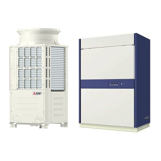
- Page 1 AIR CONDITIONERS PU(H)Y-P250YGM-A Models PUHY-P500YGM-A PFD-P250VM-E PFD-P500VM-E Service Handbook...
-
Page 2: Safety Precautions
Safety Precautions Before installing the unit, thoroughly read the following safety precautions. Observe these safety precautions for your safety. WARNING This symbol is intended to alert the user to the presence of important instructions that must be followed to avoid the risk of serious injury or death. - Page 3 WARNING When installing the unit in a small room, exercise caution After completing the service work, check for a gas leak. and take measures against leaked refrigerant reaching the If leaked refrigerant is exposed to a heat source, such as a limiting concentration.
- Page 4 Precautions for handling units for use with R410A CAUTION Do not use the existing refrigerant piping. Use a vacuum pump with a reverse-flow check valve. A large amount of chlorine that may be contained in the re- If a vacuum pump that is not equipped with a reverse-flow sidual refrigerant and refrigerating machine oil in the exist- check valve is used, the vacuum pump oil may flow into the ing piping may cause the refrigerating machine oil in the...
-
Page 5: Before Installing The Unit
Before installing the unit WARNING Do not install the unit where a gas leak may occur. When installing the unit in a hospital, take appropriate mea- sures to reduce noise interference. If gaseous refrigerant leaks and piles up around the unit, it High-frequency medical equipment may interfere with the may be ignited. - Page 6 Before installing the unit (moving and reinstalling the unit) and performing electrical work CAUTION Properly ground the unit. Periodically check the installation base for damage. Do not connect the grounding wire to a gas pipe, water pipe, If the unit is left on a damaged platform, it may fall and lightning rod, or grounding wire from a telephone pole.
- Page 7 Before the test run CAUTION Turn on the unit at least 12 hours before the test run. Do not operate the unit without panels and safety guards. Keep the unit turned on throughout the season. If the unit is Rotating, high-temperature, or high-voltage parts on the unit turned off in the middle of a season, it may result in malfunc- pose a risk of burns and/or electric shock.
-
Page 8: Table Of Contents
CONTENTS Read Before Servicing [1] Read Before Servicing......................3 [2] Necessary Tools and Materials ....................4 [3] Piping Materials ........................5 [4] Storage of Piping ........................7 [5] Pipe Processing........................7 [6] Brazing ........................... 8 [7] Air Tightness Test........................9 [8] Vacuum Drying (Evacuation).................... -
Page 10: Read Before Servicing
I Read Before Servicing [1] Read Before Servicing....................... 3 [2] Necessary Tools and Materials ..................4 [3] Piping Materials ......................... 5 [4] Storage of Piping ....................... 7 [5] Pipe Processing......................... 7 [6] Brazing..........................8 [7] Air Tightness Test......................9 [8] Vacuum Drying (Evacuation) ................... 10 [9] Refrigerant Charging ....................... - Page 11 - 2 -...
-
Page 12: Read Before Servicing
[ I Read Before Servicing ] I Read Before Servicing [1] Read Before Servicing 1. Check the type of refrigerant used in the system to be serviced. Refrigerant Type New refrigerant series split-type air-conditioners for computer rooms: R410A 2. Check the symptoms exhibited by the unit to be serviced. Refer to this service handbook for symptoms relating to the refrigerant cycle. -
Page 13: Necessary Tools And Materials
[ I Read Before Servicing ] [2] Necessary Tools and Materials Prepare the following tools and materials necessary for installing and servicing the unit. Tools for use with R410A (Adaptability of tools that are for use with R22 or R407C) 1. -
Page 14: Piping Materials
[ I Read Before Servicing ] [3] Piping Materials Do not use the existing piping! New Piping Existing Piping 1. Copper pipe materials O-material (Annealed) Soft copper pipes (annealed copper pipes). They can easily be bent with hands. 1/2H-material (Drawn) Hard copper pipes (straight pipes). - Page 15 [ I Read Before Servicing ] 4. Thickness and refrigerant type indicated on the piping materials Ask the pipe manufacturer for the symbols indicated on the piping material for new refrigerant. 5. Flare processing (O-material (Annealed) and OL-material only) The flare processing dimensions for the pipes that are used in the R410A system are larger than those in the R22 system. Flare processing dimensions (mm[in]) A dimension (mm) Pipe size (mm[in])
-
Page 16: Storage Of Piping
[ I Read Before Servicing ] [4] Storage of Piping 1. Storage location Store the pipes to be used indoors. (Warehouse at site or owner's warehouse) If they are left outdoors, dust, dirt, or moisture may infiltrate and contaminate the pipe. 2. -
Page 17: Brazing
[ I Read Before Servicing ] [6] Brazing No changes have been made in the brazing procedures. Perform brazing with special care to keep foreign objects (such as oxide scale, water, and dust) out of the refrigerant system. Example: Inside the brazed connection Use of oxidized solder for brazing Use of non-oxidized solder for brazing 1. -
Page 18: Air Tightness Test
[ I Read Before Servicing ] [7] Air Tightness Test No changes have been made in the detection method. Note that a refrigerant leak detector for R22 will not detect an R410A leak. Halide torch R22 leakage detector 1. Items to be strictly observed Pressurize the equipment with nitrogen up to the design pressure (4.15MPa), and then judge the equipment's air tight- ness, taking temperature variations into account. -
Page 19: Vacuum Drying (Evacuation)
[ I Read Before Servicing ] [8] Vacuum Drying (Evacuation) (Photo1) 15010H (Photo2) 14010 Recommended vacuum gauge: ROBINAIR 14010 Thermistor Vacuum Gauge 1. Vacuum pump with a reverse-flow check valve (Photo1) To prevent the vacuum pump oil from flowing into the refrigerant circuit during power OFF or power failure, use a vacuum pump with a reverse-flow check valve. -
Page 20: Refrigerant Charging
[ I Read Before Servicing ] [9] Refrigerant Charging Cylinder with a siphon Cylinder without a siphon Cylin- Cylin- Cylinder color R410A is pink. Refrigerant charging in the liquid state Valve Valve liquid liquid 1. Reasons R410A is a pseudo-azeotropic HFC blend (boiling point R32=-52°C, R125=-49°C) and can almost be handled the same way as a single refrigerant, such as R22. -
Page 21: Characteristics Of The Conventional And The New Refrigerants
[ I Read Before Servicing ] [11] Characteristics of the Conventional and the New Refrigerants 1. Chemical property As with R22, the new refrigerant (R410A) is low in toxicity and chemically stable nonflammable refrigerant. However, because the specific gravity of vapor refrigerant is greater than that of air, leaked refrigerant in a closed room will accumulate at the bottom of the room and may cause hypoxia. -
Page 22: Notes On Refrigerating Machine Oil
[ I Read Before Servicing ] [12] Notes on Refrigerating Machine Oil 1. Refrigerating machine oil in the HFC refrigerant system HFC type refrigerants use a refrigerating machine oil different from that used in the R22 system. Note that the ester oil used in the system has properties that are different from commercially available ester oil. Refrigerant Refrigerating machine oil Mineral oil... - Page 23 - 14 -...
-
Page 24: Ii Restrictions
II Restrictions [1] System configuration ....................... 17 [2] Types and Maximum allowable Length of Cables ............18 [3] Switch Settings and Address Settings ................20 [4] An Example of a System to which an MA Remote Controller is connected ....22 [5] Restrictions on Pipe Length..................... - Page 25 - 16 -...
-
Page 26: System Configuration
PFD-P500VM-E PUHY-P500YGM-A PU(H)Y-P250YGM-A x 2 *1 *1 When two outdoor units are connected to one indoor unit, two refrigerant circuits must be connected. Only one refrigerant circuit can be connected to the indoor unit at factory shipment. To connect two refrigerant circuits, perform some work on the unit. -
Page 27: Types And Maximum Allowable Length Of Cables
[ II Restrictions ] [2] Types and Maximum allowable Length of Cables 1. Wiring work (1) Notes 1) Have all electrical work performed by an authorized electrician according to the local regulations and instructions in this manual. WARNING Have all electrical work performed by an authorized electrician according to the local regulations and instructions in this manual, and a dedicated circuit must be used.Insufficient capacity of the power supply circuit or improper installation may result in malfunctions of the unit, electric shock, smoke, and/or fire. - Page 28 [ II Restrictions ] (2) Control wiring Different types of control wiring are used for different systems. Refer to section "[4] An Example of a System to which an MA Remote Controller is connected " before performing wiring work. [Types and maximum allowable length of cables] Control lines are categorized into 2 types: transmission line and remote controller line.
-
Page 29: Switch Settings And Address Settings
[ II Restrictions ] [3] Switch Settings and Address Settings 1. Switch setting Switch settings are necessary depending on the system configuration. Refer to the "[4] An Example of a System to which an MA Remote Controller is connected " before starting the wiring work. Shut down the power supply before making the switch settings. - Page 30 [ II Restrictions ] (3) Settings of MA remote controller Main/Sub switching switch (When MA remote controller is used: factory setting "Main") Main/sub settings are available on the MA remote controller. When two remote controllers are connected, set either of them to "Sub".
-
Page 31: An Example Of A System To Which An Ma Remote Controller Is Connected
[ II Restrictions ] [4] An Example of a System to which an MA Remote Controller is connected 1. System with one refrigerant Sample control wiring Leave the male connector on CN41 as it is. *Two indoor controllers (controller circuit boards) TB5-1 are equipped in the indoor unit (P500). - Page 32 [ II Restrictions ] Wiring method/address setting method 1) Indoor/outdoor transmission line Connect M1, M2 terminals of the indoor/outdoor transmission line terminal block (TB3) on the outdoor unit (OC) and A1, B1 terminals of the indoor/outdoor terminal block (TB5-1) on the indoor unit (IC). (Non-polarized 2-core cable) Only use shielded cables.
- Page 33 [ II Restrictions ] 2. System with two refrigerant circuits Sample control wiring CN40 CN41 Replace TB5-1 *Two indoor controllers (controller circuit boards) M1M2S M1M2 A1 B1 S are equipped in the indoor unit (P500). TB15 Connect Leave the male connector on CN41 as it is.
- Page 34 [ II Restrictions ] Wiring method/address setting method 1) Indoor/outdoor transmission line Connect M1, M2 terminals of the indoor/outdoor transmission line terminal block (TB3) on the outdoor unit (OC) and A1, B1 terminals of the indoor/outdoor terminal block (TB5-1) on the indoor unit (IC). (Non-polarized 2-core cable) Only use shielded cables.
- Page 35 [ II Restrictions ] 3. System in which two MA remote controllers are connected to one indoor unit Sample control wiring Leave the male connector on CN41 as it is. TB5-1 *Two indoor controllers (controller circuit boards) M1M2S M1M2 A1 B1 S are equipped in the indoor unit (P500).
- Page 36 [ II Restrictions ] Wiring method/address setting method 1) Indoor/outdoor transmission line Same as [4] 1. 2) MA remote controller wiring [When 2 remote controllers are connected to the system] When two remote controllers are connected to the system, connect terminals 1 and 2 of the terminal block (TB15) on the indoor unit (IC) to the terminal block on the MA remote controllers (option).
- Page 37 [ II Restrictions ] 4. System in which two indoor units are grouped with the MA remote controller Sample control wiring Leave the male Leave the male connector on connector on CN41 as it is. CN41 as it is. *Two indoor controllers (controller circuit boards) are equipped in the indoor unit (P500).
- Page 38 [ II Restrictions ] Wiring method/address setting method 1) Indoor/outdoor transmission line Same as [4] 1. 2) MA remote controller wiring [Group operation of indoor units] To perform a group operation of indoor units (IC), daisy-chain terminals 1 and 2 on the terminal block (TB15) on all indoor units (IC).
-
Page 39: Restrictions On Pipe Length
[ II Restrictions ] [5] Restrictions on Pipe Length 1. Sample connection (1) System with one refrigerant circuit Outdoor unit Indoor (2) System with two refrigerant circuits Outdoor unit Indoor Allowable length Total pipe length (L) from the outdoor Actual length 150m or less unit to thefarthest indoor unit Allowable height Height difference between the indoor... -
Page 40: Iii Outdoor Unit Components
III Outdoor Unit Components [1] Outdoor Unit Components and Refrigerant Circuit ............33 [2] Control Box of the Outdoor Unit..................37 [3] Outdoor Unit Circuit Board....................39 - 31 -... - Page 41 - 32 -...
-
Page 42: Outdoor Unit Components And Refrigerant Circuit
[ III Outdoor Unit Components ] III Outdoor Unit Components [1] Outdoor Unit Components and Refrigerant Circuit 1. PU(H)Y-P250YGM-A model (1) Front view of a outdoor unit Fan guard Heat exchanger (2) Rear view of a outdoor unit Fan guard... - Page 43 [ III Outdoor Unit Components ] (3) Front view of a refrigerant circuit High-pressure check joint High-pressure pressure sensor Pressure switch Discharge muffler 4-way valve Accumulator (21S4a) Inverter Drier compressor Low-pressure check joint Gas-side ball valve Liquid-side ball valve (4) Rear view of a refrigerant circuit Linear expansion 4-way valve valve (LEV1)
- Page 44 [ III Outdoor Unit Components ] 2. PUHY-P500YGM-A model (1) Front view of a outdoor unit Fan guard Heat exchanger (2) Rear view of a outdoor unit Fan guard Heat exchanger - 35 -...
- Page 45 [ III Outdoor Unit Components ] (3) Front view of a refrigerant circuit Oil separator (No.1) Oil separator (No.2) Pressure switch Accumulator Inverter compressor (No.1) Oil balance pipe Commercial power supply compressor (No.2) (4) Rear view of a refrigerant circuit <Front view>...
-
Page 46: Control Box Of The Outdoor Unit
[ III Outdoor Unit Components ] [2] Control Box of the Outdoor Unit 1. PU(H)Y-P250YGM-A model (1) Appearance Control circuit board Power circuit board Transmission line Choke coil terminal block (L1, L2) for centralized control (TB7) Filter board Transformer Indoor/outdoor... - Page 47 [ III Outdoor Unit Components ] 2. PUHY-P500YGM-A model (1) Appearance Relay board Power circuit board Control circuit board Transmission line terminal block for centralized control (TB7) Filter board Indoor/outdoor transmission Choke coil terminal block (L1, L2) Transformer Power supply terminal (TB3) block (TB1) (2) Under the circuit board cover...
-
Page 48: Outdoor Unit Circuit Board
[ III Outdoor Unit Components ] [3] Outdoor Unit Circuit Board 1. Control circuit board CNRS3A CNS1 CNS2 CN40 CN41 CNRS3B CN38 CNVCC1 Controlled source input CNRT1 1 - 2 DC30V 1 - 3 DC30V CN52C 4 - 5 DC7V Control for 4 - 6 DC12V 52C1... - Page 49 [ III Outdoor Unit Components ] 2. Power circuit board CNVDC CN15V2 Power supply for IPM control CNVCC1 Power supply 1 - 2 DC30V 1 - 3 DC30V 4 - 5 DC7V 4 - 6 DC12V 7 - 8 DC7V CN52C CNDR2 CNAC2...
- Page 50 [ III Outdoor Unit Components ] 3. Fan control board CNVDC DC bus voltage input CNINV Fan motor output Fuse CNRS2 1 - 3 LED1 LED2 IPM (back) CNTR 4. Relay board CNRT2 1 - 5 52C2, 52F, CH12 Power input (AC220~240V) CN51C2 CNOUT2 51C2...
- Page 51 [ III Outdoor Unit Components ] 5. Filter board CNOUT CNIN Controlled Controlled CNFG source output CNL1 CNL2 source input 6. G/A board CNDC1 CNDC2 CN15V1 CNIPM1 CNDR1 - 42 -...
-
Page 52: Iv Indoor Unit Components
IV Indoor Unit Components [1] External Dimensions......................45 [2] Indoor Unit Components and Internal Structure .............. 47 [3] Control Box of the Indoor Unit ..................51 [4] Indoor Unit Circuit Board ....................52 [5] Separating the top and bottom of the unit................ 53 - 43 -... - Page 53 - 44 -...
-
Page 54: External Dimensions
[ IV Indoor Unit Components ] IV Indoor Unit Components [1] External Dimensions 1. PFD-P250VM-E model Unit : mm - 45 -... - Page 55 [ IV Indoor Unit Components ] 2. PFD-P500VM-E model Unit : mm - 46 -...
-
Page 56: Indoor Unit Components And Internal Structure
[ IV Indoor Unit Components ] [2] Indoor Unit Components and Internal Structure 1. PFD-P250VM-E model (1) Front view of a indoor unit Panel for air filter maintenance Panel for refrigerant circuit maintenance Operation panel (remote controller) Lock key X 2 Panel for controller/fan related parts maintenance Display lamp (2) Rear view of a indoor unit... - Page 57 [ IV Indoor Unit Components ] (3) Front view of internal structure Suction temperature thermistor (on the right side of heat exchanger) Linear expansion valve (LEV) Air filter Heat exchanger X 2 (front / back) Sub drain pan Drain pan Drain hose Pulley X 2 Pipes (gas/liquid)
- Page 58 [ IV Indoor Unit Components ] 2. PFD-P500VM-E model (1) Front view of a indoor unit Panel for air filter maintenance Panel for refrigerant circuit maintenance Operation panel (remote controller) Display lamp Panel for controller maintenance Lock key X 4 Panel for fan related parts maintenance (2) Rear view of a indoor unit - 49 -...
- Page 59 [ IV Indoor Unit Components ] (3) Front view of internal structure Air filter Suction temperature thermistor (on the right side of heat exchanger) Sub drain pan Heat exchanger X 2 (front:No. 1; back:No. 2) Linear expansion valve (LEV) Drain pan Pulley X 2 Drain hose Bearing...
-
Page 60: Control Box Of The Indoor Unit
[ IV Indoor Unit Components ] [3] Control Box of the Indoor Unit 1. PFD-P250VM-E model Relay(X11,Z1,Z3) Transformer Controller board Electro magnetic contactor (52F) Surge breaker (51F) Fuse (F1) Motor wiring Surge absorber board Circuit board for external I/O Power supply terminal bed Terminal block for transmission line (upper) Terminal block for MA remote controller (lower) 2. -
Page 61: Indoor Unit Circuit Board
[ IV Indoor Unit Components ] [4] Indoor Unit Circuit Board 1. PFD-P250,P500VM-E models (1) Indoor Control Board CN3A Remote controller connection CN33 Power supply output Lamp output (to transformer) CN60 CN51 CN90 LEV output Drain pump Switch input Power supply Fan output output CN24... -
Page 62: Separating The Top And Bottom Of The Unit
[ IV Indoor Unit Components ] [5] Separating the top and bottom of the unit The top and the bottom of the unit can be separated. (Requires brazing) When separating the top and the bottom of the unit, perform the work on a level surface. Follow the procedures below when separating the sections. - Page 63 [ IV Indoor Unit Components ] <Model 250> Connect the wire from the lamp assy. Bend the wire once, and fix the wire. (the wire from the lamp assy.) Connect the wire from the lamp assy. Fix the wire from the fan motor. <Model 500>...
- Page 64 [ IV Indoor Unit Components ] <Model 250> Unbraze these sections Heat exchanger (2 places on the gas pipe/ (liquid pipe) expanded part) Heat exchanger (gas pipe) Unbraze this section (1 place on the liquid pipe/ upper part of the strainer) Drain pan Unbraze these sections <Model 500>...
- Page 65 [ IV Indoor Unit Components ] To put the top and bottom sections of the unit together, follow the procedures above in the reverse order. Check to make sure that the frame is perpendicular to the horizontal plane before putting the panels together. When the frames will not fit back into place, loosen bolt 2 as shown in [Fig.1], place the frames, and tighten bolt 2 .
-
Page 66: V Electrical Wiring Diagram
V Electrical Wiring Diagram [1] Electrical Wiring Diagram of the Outdoor Unit ..............59 [2] Electrical Wiring Diagram of the Indoor Unit..............61 - 57 -... - Page 67 - 58 -...
-
Page 68: Electrical Wiring Diagram Of The Outdoor Unit
[ V Electrical Wiring Diagram ] V Electrical Wiring Diagram [1] Electrical Wiring Diagram of the Outdoor Unit 1. PU(H)Y-P250YGM-A model - 59 -... - Page 69 [ V Electrical Wiring Diagram ] 2. PUHY-P500YGM-A model - 60 -...
-
Page 70: Electrical Wiring Diagram Of The Indoor Unit
[ V Electrical Wiring Diagram ] [2] Electrical Wiring Diagram of the Indoor Unit 1. PFD-P250VM-E model - 61 -... - Page 71 [ V Electrical Wiring Diagram ] 2. PFD-P500VM-E model - 62 -...
-
Page 72: Vi Refrigerant Circuit
VI Refrigerant Circuit [1] Refrigerant Circuit Diagram ..................... 65 [2] Principal Parts and Functions ..................68 - 63 -... - Page 73 - 64 -...
-
Page 74: Refrigerant Circuit Diagram
[ VI Refrigerant Circuit ] VI Refrigerant Circuit [1] Refrigerant Circuit Diagram 1. System with one refrigerant (1) PU(H)Y-P250YGM-A model - 65 -... - Page 75 [ VI Refrigerant Circuit ] (2) PUHY-P500YGM-A model - 66 -...
- Page 76 [ VI Refrigerant Circuit ] 2. System with two refrigerant circuits (1) PU(H)Y-P250YGM-A model - 67 -...
-
Page 77: Principal Parts And Functions
[ VI Refrigerant Circuit ] [2] Principal Parts and Functions 1. Outdoor unit Part Symbols Check Notes Usage Specifications name (functions) method Compres- Adjusts the amount of circulating Low-pressure shell refrigerant by adjusting the oper- scroll compressor ating frequency based on the op- Wirewound resistance erating pressure data 20°C : 0.583 ohm... - Page 78 [ VI Refrigerant Circuit ] Part Symbols Check Notes Usage Specifications name (functions) method Ther- TH11 TH12 is 1. Detects discharge air temper- Resis- = 7.465k mistor TH12 available ature tance = 4057 25/120 (Discharge) only on 2. Provides high-pressure pro- check P500 tection...
- Page 79 [ VI Refrigerant Circuit ] Part Symbols Check Notes Usage Specifications name (functions) method Linear ex- Adjusts the amount of bypass DC12V Same as pansion (SC coil) flow from the liquid pipe on the Opening of a valve driven by a indoor LEV valve outdoor unit during cooling...
- Page 80 [ VI Refrigerant Circuit ] 2. Indoor unit Part Symbols Notes Usage Specifications Check method name (functions) Linear ex- 1. Adjusts superheat at the heat DC12V Continuity check pansion exchanger outlet of the indoor Opening of a valve driven by with a tester valve unit during cooling...
- Page 81 - 72 -...
-
Page 82: Vii Control
VII Control [1] Functions and Factory Settings of the Dipswitches ............75 [2] Controlling the Outdoor Unit .................... 80 [3] Controlling the Indoor Unit ....................88 [4] Operation Flow Chart....................... 92 - 73 -... - Page 83 - 74 -...
-
Page 84: Functions And Factory Settings Of The Dipswitches
[ VII Control ] VII Control [1] Functions and Factory Settings of the Dipswitches 1. Outdoor unit (1) Main board Function according to switch setting Switch setting timing Switch Function Unit address setting Set to 00 or 51-100 with the dial switch Before power on For self-diagnosis/op- Refer to the LED monitor display on 1-10... - Page 85 [ VII Control ] Function according to switch setting Switch setting timing Switch Function Reset of the integrat- ed operation time Val- Disabled Enabled Anytime after power on id/Invalid (comp 1 side) Reset of the integrat- ed operation time Val- Disabled Enabled Anytime after power on...
- Page 86 [ VII Control ] (2) Compressor INV board Function according to switch Switch setting timing setting Switch Function Enabling/disabling the following error Error detec- Error detec- Anytime after power on detection functions; tion enabled tion disabled ACCT or DCCT sensor circuit error (530X Detail No.
- Page 87 [ VII Control ] 2. Function of the switch (Indoor unit) (1) Dipswitches [SW1,3,7] Function according to switch setting Switch setting timing Notes Switch Function Function selection Heat pump Cooling only Not available Available Clogged filter detection Filter check reminder 100h 2500h time setting...
- Page 88 [ VII Control ] [SW8] Function Operation by switch setting Switch setting timing Compulsory thermo OFF setting during test run Normal control Anytime (used in the grouped indoor units connected to after power on Compulsory thermo OFF different outdoor units) (2) Slide switches Switch Function...
-
Page 89: Controlling The Outdoor Unit
[ VII Control ] [2] Controlling the Outdoor Unit -1- Initial Control When the power is turned on, the initial processing of the microcomputer is given top priority. During the initial processing, control processing of the operation signal is suspended. The control processing is resumed after the initial processing is completed. - Page 90 [ VII Control ] -4- Compressor Frequency Control Depending on the capacity required, the frequency of the compressor is controlled to bring the evaporation temperature (Te) close to the target evaporation temperature (Tem) during cooling operation, and to keep constant condensing temper- ature (49°C =2.88MPa) during heating operation.
-
Page 91: Defrost Operation Control
[ VII Control ] -5- Defrost Operation Control (1) Starting the defrost operation Defrost operation is started when the pipe temperature (TH5) of -10°C or below (-8°C or below for P500-type) has con- tinuously been detected for 3 minutes after the integrated compressor operation time of 50 minutes have passed (90 min- utes when the defrost prohibit timer is set to 90 minutes). -
Page 92: Refrigerant Recovery Control
[ VII Control ] -6- Refrigerant Recovery Control Recovery of refrigerant is performed during heating operation to prevent the refrigerant from accumulating inside the unit while it is stopped (unit in fan mode), or inside the indoor unit that is in cooling mode or in heating mode with thermo off. It is also performed during cooling operation to prevent an excessive amount of refrigerant from accumulating in the outdoor heat exchanger. - Page 93 [ VII Control ] -7- Capacity Control of Outdoor Fan and Heat Exchanger (1) Control method The outdoor fan air flow rate is controlled to keep constant evaporation temperature during cooling operation and to keep constant condensing temperature during heating operation. The capacity of the heat exchanger on the P500 model of outdoors is controlled by the 4-way valve (21S4b) or the sole- noid valve (SV5b).
- Page 94 [ VII Control ] -9- Control at Initial Start-up When the unit is started for the first time, it will run the following course of operation. (1) Flow chart of initial operation mode Start of initial operation mode Step 1 Operation of No.1 compressor only P250 60 Hz.
-
Page 95: Emergency Operation Mode
[ VII Control ] -10- Emergency Operation Mode When compressors (No.1 or No.2) fails, the unit goes into the emergency operation mode to respond to the problem. The unit can be put into this mode by performing an error reset on the remote controller. (1) Starting the emergency operation 1) When an error occurs, the error source and the error code will be displayed on the display on the remote controller. -
Page 96: Operation Mode
[ VII Control ] -11- Capacity Control between Outdoor Units (when two refrigerant circuits are connect- The following two capacity control methods between indoor units are available. Control to make only one of the outdoor units (which has the smaller address) operate and keep running during low-load hours at startup. -
Page 97: Controlling The Indoor Unit
[ VII Control ] [3] Controlling the Indoor Unit <Indoor unit control> There are two controller circuit boards with two refrigerant circuits inside the indoor unit of 20 HP. There is one controller circuit board with one refrigerant circuit. Each refrigerant circuit is controlled independently (in case of one refrigerant circuit, one-to-one control of indoor unit and outdoor unit) in the following method. -
Page 98: Actuator Control
[ VII Control ] -2- Actuator Control (1) LEV Control • The degree of LEV opening is set to the initial degree depending on the condensing pressure at start-up. • After the start-up, the degree of LEV opening is controlled every minute so that the superheat detected by the thermistors TH22 (liquid pipe) and TH23 (gas pipe) of the indoor unit can be within a certain range. - Page 99 [ VII Control ] Miscellaneous When the errors other than described in the chart, the unit makes an error stop without performing emergency operation. (Only the indoor fan operates, however; it stops when the fan is in trouble.) When one of the two refrigerant circuits, the outdoor unit with the refrigerant circuit in error performs emergency operation or makes an error stop, while the other outdoor unit keeps normal operation.
- Page 100 [ VII Control ] -7- Switching Between Pulse and Level of MA Remote Controller External Input The start/stop operation can be performed by either of the MA remote controller or the external input (pulse/level). DIPSW on the address circuit board (No.1 and No. 2) Valid operation SW1-9 = OFF External input (level)
-
Page 101: Operation Flow Chart
[ VII Control ] [4] Operation Flow Chart 1. Mode determination flowchart (1) Indoor unit (cooling, heating, fan mode) [Standard] Start Normal operation Error Breaker Unit in the stopped state turned on From outdoor unit Operation SW turned on 1. Protection function self-holding cancelled. - Page 102 [ VII Control ] (2) Outdoor unit (cooling and heating modes) Start Normal operation Error Breaker turned on Unit in the stopped state "HO" blinks *Note 1 on the remote controller Indoor units registered to the remote controller 2 From indoor unit Operation command 1.
- Page 103 [ VII Control ] 2. Operations in each mode (1) Cooling operation Cooling operation Normal operation During test run mode 4-way valve OFF Unit in the stopped state Indoor unit fan *Note 1 operation Test run mode Thermostat ON *Note 2 3-minute restart prevention 1.
- Page 104 [ VII Control ] (2) Heating operation (For warming up the indoor unit) Normal operation Defrost operation Heating operation Unit in the stopped state *Note 1,2 During test run mode Defrost operation 4-way valve ON 4-way valve OFF 1. Indoor unit fan stops (*Note.3) Test run mode 2.
- Page 105 - 96 -...
-
Page 106: Viii Test Run Mode
VIII Test Run Mode [1] Items to be checked before a Test Run................99 [2] Test Run Method ......................100 [3] Operating Characteristic and Refrigerant Amount............101 [4] Adjusting the Refrigerant Amount.................. 102 [5] Refrigerant Amount Adjust Mode................... 104 [6] The following symptoms are normal................106 [7] Standard Operation Data (Reference Data) .............. - Page 107 - 98 -...
-
Page 108: Items To Be Checked Before A Test Run
[ VIII Test Run Mode ] VIII Test Run Mode [1] Items to be checked before a Test Run Check for refrigerant leak and loose cables and connectors. Measure the insulation resistance between the power supply terminal block and the ground with a 500V megger and make sure it reads at least 1.0Mohm. -
Page 109: Test Run Method
[ VIII Test Run Mode ] [2] Test Run Method Procedures Note 1 When two refrigerant circuits are connected, both refrigerant circuits start running when the operation is started with the remote controller without setting the SW8 on the indoor unit as shown on the right. To enable each refrigerant circuit to operate individually, the setting of the SW8 shown on the right is required. -
Page 110: Operating Characteristic And Refrigerant Amount
[ VIII Test Run Mode ] [3] Operating Characteristic and Refrigerant Amount It is important to have a clear understanding of the characteristics of refrigerant and the operating characteristics of air condi- tioners before attempting to adjust the refrigerant amount in a given system. 1. -
Page 111: Adjusting The Refrigerant Amount
[ VIII Test Run Mode ] [4] Adjusting the Refrigerant Amount 1. Symptoms Overcharging or undercharging of refrigerant can cause the following symptoms : Before attempting to adjust the amount of refrigerant in the system, thoroughly check the operating conditions of the sys- tem. - Page 112 Amount of refrigerant to be charged (kg) = 0.2 x 150 + 4.0 = 34.0kg The final result will be as follows: Amount of refrigerant to be charged = 34.0kg (3) Sample: Outdoor PU(H)Y-P250YGM-A x 2, Indoor PFD-P500VM-E 9.52 Outdoor Indoor 9.52...
-
Page 113: Refrigerant Amount Adjust Mode
[ VIII Test Run Mode ] [5] Refrigerant Amount Adjust Mode 1. Procedures Follow the procedures below to add or extract refrigerant in the cooling mode as necessary. When the function switch switches (SW2-4) on the main board on the outdoor unit are turned to ON, the unit will go into the refrigerant amount adjust mode. - Page 114 [ VIII Test Run Mode ] Start SW2-4 ON Put all indoor units in the test run mode *Refer to the previous page for *Notes 1-4 in the chart. and run the units in cooling mode. Has the initial start-up mode been completed? Has it been at least 30 minutes since...
-
Page 115: The Following Symptoms Are Normal
[ VIII Test Run Mode ] [6] The following symptoms are normal. Remote controller dis- Symptoms Cause play When the main power is turned on, "HO" blinks on the The system is starting up. Wait until the blinking display the display shown on the right ap- display. -
Page 116: Standard Operation Data (Reference Data)
[ VIII Test Run Mode ] [7] Standard Operation Data (Reference Data) (1) Cooling operation Indoor unit model Outdoor unit model Operation PFD-P500VM-E PUHY-P500YGM-A Ambient Indoor 27/19 Operat- tempera- ing condi- Outdoor 35/- ture °C tions Piping Total pipe length Outdoor Compressor frequency 50Hz:70/50... - Page 117 - 108 -...
-
Page 118: Ix Troubleshooting
IX Troubleshooting [1] Error code Lists......................111 [2] Responding to Error Display on the Remote Controller..........114 [3] Investigation of Transmission Wave Shape/Noise ............144 [4] Troubleshooting Principal Parts..................147 [5] Refrigerant Leak ......................167 [6] Compressor Replacement Instructions (Only P500 type)..........168 [7] Collecting the Cooling Liquid from the Accumulator (Only P500 type) ...... - Page 119 - 110 -...
-
Page 120: Error Code Lists
[ IX Troubleshooting ] IX Troubleshooting [1] Error code Lists Searched unit Error Prelimi- (prelim- Error nary inary) Error code definition Notes Code error detail code code 4300 0403 Serial communication error 4305 (Note) Abnormal discharge air temperature, 1102 1202 Abnormal discharge temperature sensor 1301 Abnormal low pressure... - Page 121 [ IX Troubleshooting ] Searched unit Error Prelimi- (prelim- Error nary inary) Error code definition Notes Code error detail code code Suction air temperature (TH21) Temperature sensor 5101 1202 failure Discharge air temperature (TH11, TH12) Temperature sensor 5102 Indoor piping (TH22) failure Temperature sensor 5103...
- Page 122 [ IX Troubleshooting ] Searched unit Error Prelimi- (prelim- Error nary inary) Error code definition Notes Code error detail code code 7100 Total capacity error 7101 Capacity code error 7102 Error in the number of connected units 7105 Address setting error 7110 Unset unit connection information error 7111...
-
Page 123: Responding To Error Display On The Remote Controller
[ IX Troubleshooting ] [2] Responding to Error Display on the Remote Controller 1. Mechanical system Error definition and error Error Code Cause Check method and remedy detection method 0403 Serial commu- Serial communication er- (1) Faulty wiring Check for wiring between the con- nication error ror between the main nector (CNRS3B) on the main board... - Page 124 [ IX Troubleshooting ] Error definition and error Error Code Cause Check method and remedy detection method 1102 Abnormal dis- 1. If the discharge tem- (1) Gas leak, gas shortage Refer to the page on refrigerant charge air tem- perature of 120°C or amount evaluation.
- Page 125 [ IX Troubleshooting ] Error definition and error Error Code Cause Check method and remedy detection method 1301 Abnormal low When starting the com- (1) Inner pressure drop due to Refer to the section on troubleshoot- pressure pressor from Stop Mode a leakage.
- Page 126 [ IX Troubleshooting ] Error definition and error Error Code Cause Check method and remedy detection method 1302 Abnormal high (1) LEV failure on the indoor Perform a heating operation and 1. If the pressure of 3.87MPa or higher is detected by the pressure 1 unit check the operation.
- Page 127 [ IX Troubleshooting ] Error definition and error Error Code Cause Check method and remedy detection method 1500 Refrigerant An error can be detected (1) Overcharged refrigerant Refer to the page on refrigerant overcharge by the discharge temper- amount evaluation. ature superheat.
- Page 128 [ IX Troubleshooting ] Error definition and error Error Code Cause Check method and remedy detection method 4103 Reverse 1. The operation cannot (1) Faulty wiring Check whether the phase of phase/open be started because of the power supply terminal phase the reserve phase of block (TB1) is normal.
- Page 129 [ IX Troubleshooting ] Error definition and error Error Code Cause Check method and remedy detection method 4109 Abnormal fan If the auxiliary relay X4 (1) Overcurrent circuit breaker Check that the fan is not stalled, the (IC) (for detecting fan abnor- (51F) trip bearing is not worn out, and the pul- mality) is not excited for a...
- Page 130 [ IX Troubleshooting ] Error definition and error Error Code Cause Check method and remedy detection method 4220 Bus voltage If Vdc 289V or less is de- (1) Power supply environment Check whether the unit makes an instanta- neous stop when the detection result is ab- 4225 drop tected during Inverter op-...
- Page 131 [ IX Troubleshooting ] Error definition and error Error Code Cause Check method and remedy detection method 4220 Logic error If only the H/W error logic In the case of 4220 Refer to 9 [4]-6-(2) [1] and replace 4225 (Detail code circuit operates, and no (1) External noise the G/A board.
- Page 132 [ IX Troubleshooting ] Error definition and error Error Code Cause Check method and remedy detection method 4240 Overload pro- When the greater output (1) Short cycle of the air pas- Check that the waste heat from the 4245 tection current (Iac) than the sage outdoor unit fan is not short cycled.
- Page 133 [ IX Troubleshooting ] Error definition and error Error Code Cause Check method and remedy detection method 4250 IPM error When an error signal of In the case of 4250 Same as 4230 error 4255 (Detail code IPM is detected (1) Inverter output related 101) (2) Same as 4230 error...
- Page 134 [ IX Troubleshooting ] Temperature sensor failure (indoor unit) Error definition and error Error Code Cause Check method and remedy detection method 5101 Air inlet If a short or an open is (1) Thermistor failure Check the thermistor resistor. detected during thermo- (2) Connector contact failure 0°C : 15 kohm 5102...
- Page 135 [ IX Troubleshooting ] Temperature sensor failure (outdoor unit) Error definition and error Error Code Cause Check method and remedy detection method 5101 Discharge 1. When a short (high (1) Thermistor failure Check thermistor resistance. (TH11,TH12) temperature intake) or an open (low tempera- 5105 Piping (2) Pinched lead wire...
- Page 136 [ IX Troubleshooting ] Error definition and error Error Code Cause Check method and remedy detection method 5110 Heat sink fail- When a short or an open (1) THHS sensor failure Check for short circuit in THHS sen- of THHS is detected just sor.
- Page 137 [ IX Troubleshooting ] Error definition and error Error Code Cause Check method and remedy detection method 5301 ACCT sensor When an error value is (1) Compressor INV board Refer to 9 [4]-6-(2) [1] circuit failure detected with the ACCT failure "Check the compressor INV board (Detail code...
- Page 138 [ IX Troubleshooting ] 2. Transmission error Error Error definition and error detec- Cause Check method and remedy Code tion method 6600 Address overlaps (1) Two or more outdoor units, in- If the error "6600" occurs, reset the error The error is detected when the door units, or the main remote (or stop the unit) using the MA remote con- same address is transmitted...
- Page 139 [ IX Troubleshooting ] Error Error definition and error detec- Check method and remedy Code tion method 6602 Transmission processor hard- (1) When the wiring work of or the polarity of either the indoor or outdoor trans- ware error mission line is performed or is changed while the power is on, the transmitted data will collide, the wave shape will be changed, and an error will be detect- Although "0"...
- Page 140 [ IX Troubleshooting ] Error Error definition and error detec- Cause Check method and remedy Code tion method 6603 Transmission circuit bus-busy (1) The transmission processor No noise indicates that the error source cannot be transmitted as the controller is a failure. 1.
- Page 141 [ IX Troubleshooting ] (1) System with the main remote controller connected Error Code Error definition and error detection method 6607 No ACK abnormality The error is detected when no acknowledgement (ACK signal) is received after the transmission. (eg. When the data is transmitted six times in a row with 30 seconds interval, the error is detected on the transmission side.) Note: The address/attribute appeared on the display on the main remote controller indicates the controller where an error occurs.
- Page 142 [ IX Troubleshooting ] (2) Errors that are not limited to a particular system Error Code Error definition and error detection method 6607 No ACK abnormality The error is detected when no acknowledgement (ACK signal) is received after the (Contin- transmission.
- Page 143 [ IX Troubleshooting ] Error Error definition and error detec- Cause Check method and remedy Code tion method 6831 MA communication error or no (1) Contact failure of the remote 1) Check for disconnected or loose reception error controller lines of MA remote transmission lines for the indoor units Communication between the controller or the indoor unit.
- Page 144 [ IX Troubleshooting ] 3. System error Error Error definition and error Error source Cause Check method and remedy Code detection method 7100 Outdoor unit Total capacity error The model total of indoor units 1) Check the model total (capacity in the system with one outdoor code total) of indoor units con- The model total of indoor...
- Page 145 [ IX Troubleshooting ] Error Error definition and error Error source Cause Check method and remedy Code detection method 7110 The indoor unit cannot be (1) Shutdown of the power of Check that the power supply of the operated as the connec- the power supply exten- power supply extension unit for tion between indoor units...
- Page 146 [ IX Troubleshooting ] 4. Troubleshooting according to malfunction of the remote controller/main remote controller or the external input error (1) In the case of MA remote controller Phenomena Cause Check method and remedy Even if the operation button on 1.
- Page 147 [ IX Troubleshooting ] Phenomena Cause Check method and remedy When the remote controller op- 1. The power for the M-NET trans- (1) If the causes 1-5 apply, LED5 (M-NET eration SW is turned on, the mission line is not supplied from transmission voltage display) on the in- operation status briefly ap- the outdoor unit.
- Page 148 [ IX Troubleshooting ] Phenomena Cause "HO" display on the remote 1. The power for the M-NET transmission line is not supplied from the outdoor unit. controller does not disappear, (i) The main power of the outdoor unit is not turned on. and no operation is performed (ii) The connector on the circuit board of the outdoor unit is disconnected.
-
Page 149: Flow Chart
[ IX Troubleshooting ] Flow chart Flowchart when the MA remote controller cannot be operated The MA remote controller cannot be operated. No display appears on the MA remote controller. Running group operation with the MA remote controller LED 2 are extinguished on the controller circuit boards of other indoor units. - Page 150 [ IX Troubleshooting ] (2) In case of main remote controller Phenomena Cause Check method and remedy Although cooling operation 1. Compressor frequency does not (1) Check the pressure difference between starts with the normal remote rise sufficiently. the inlet temperature (TH22) and the controller display, the capacity Wrong detection of the tempera- actual temperature by monitoring with...
- Page 151 [ IX Troubleshooting ] Phenomena Cause Check method and remedy Although cooling operation 4. Long piping length Confirm that the characteristic of capacity starts with the normal remote The cooling capacity varies great- drop due to piping length. controller display, the capacity ly depending on the pressure The piping pressure loss can be assumed is not enough.
- Page 152 [ IX Troubleshooting ] (3) In case of external input (including operation mode) The unit cannot be started or stopped with the external input. DipSW 1-10 on the controller circuit board of the indoor unit: Other than OFF 3-8:ON Make the DipSW settings as specified. Normal/inspection switching SW on the indoor unit: "Inspection"...
-
Page 153: Investigation Of Transmission Wave Shape/Noise
[ IX Troubleshooting ] [3] Investigation of Transmission Wave Shape/Noise 1. M-NET transmission Control is performed by exchanging signals between the outdoor unit and the indoor unit (M-NET remote controller) through M-NET transmission. Noise interference on the transmission line will interrupt the normal transmission, leading to erroneous operation. - Page 154 [ IX Troubleshooting ] (3) Check method and remedy 1) Measures against noise Check the followings when noise exists on the wave or the errors described in (1) occur. Error code definition Remedy Check 1. The transmission line and the power Isolate the transmission line from the power line (5cm or that the 220~240 V line are not wired too...
- Page 155 [ IX Troubleshooting ] 2. MA remote controller transmission The communication between the MA remote controller and the indoor unit is performed with current tone burst. (1) Symptoms caused by noise interference on the transmission line If noise is generated on the transmission line, and the communication between the MA remote controller and the indoor unit is interrupted for 3 minutes in a row, MA transmission error (6831) will occur.
-
Page 156: Troubleshooting Principal Parts
[ IX Troubleshooting ] [4] Troubleshooting Principal Parts -1- High-Prmessure Sensor (63HS) 1. Compare the pressure that is detected by the high pressure sensor, and the high-pressure gauge pres- sure to check for failure. Set the digital display switch (SW1) as shown below to display the pressure that is detected by the high pressure sensor on the light emitting diode. - Page 157 [ IX Troubleshooting ] -2- Low-Pressure Sensor (63LS) 1. Compare the pressure that is detected by the low pressure sensor, and the low pressure gauge pressure to check for failure. Set the digital display switch (SW1) as shown below to display the pressure that is detected by the low pressure sensor on the self-diagnosis LED.
-
Page 158: Solenoid Valve
[ IX Troubleshooting ] -3- Solenoid Valve Check whether the output signal from the control board and the operation of the solenoid valve match. Setting the self-diagnosis switch (SW1) as shown in the figure below causes the ON signal of each relay to be output to the LED's. - Page 159 [ IX Troubleshooting ] (4) In case of SV1 (Bypass valve) This solenoid valve opens when powered (Relay ON). 1) At compressor start-up, the SV1 turns on for 4 minutes, and the operation can be checked by the self-diagnosis LED display and the closing sound. 2) To check whether the valve is open or closed, check the change of the SV1 downstream piping temperature while the valve is being powered.Even when the valve is closed, high-temperature refrigerant flows inside the capillary next to the valve.
- Page 160 [ IX Troubleshooting ] -4- Outdoor Unit Fan To check the revolution of the fan, check the inverter output state on the self-diagnosis LED, as the inverter on the outdoor fan controls the revolutions of the fan.The revolution of the fan is approximately 600rpm at full speed. When starting the fan, the fan runs at full speed for 5 seconds.
- Page 161 [ IX Troubleshooting ] -5- LEV LEV operation The LEV (indoor: linear expansion valve), SLEV1, and LEV1 receive pulse signal from the indoor and outdoor main circuit boards, and drive the valve by stepping motor. (1) Indoor unit LEV The valve opening changes according to the number of pulses. <Connections between the indoor/outdoor control board and LEV (indoor expansion valve)>...
- Page 162 [ IX Troubleshooting ] (2) Outdoor unit LEV The valve opening changes according to the number of pulses. <Connections between the outdoor unit MAIN board and LEV1 (outdoor unit expansion valve)> Outdoor MAIN board DC 12V Brown Drive circuit Blue Orange Yellow White...
- Page 163 [ IX Troubleshooting ] (3) Judgment methods and possible failure mode Note: The specifications of the outdoor unit (outdoor unit LEV) and the indoor unit (Indoor unit LEV) differ.Therefore, reme- dies for each failure may vary. Check the remedy specified for the appropriate LEV as indicated in the right column. Malfunction Judgment method Remedy...
- Page 164 [ IX Troubleshooting ] (4) Outdoor unit LEV1 coil removal procedure LEV component As shown in the figure, the outdoor unit LEV is made in such a way that the coils and the body can be separated. Body Coils Stopper Lead wire Removing the coils: Fasten the body tightly at the bottom (Part A in the figure) so that the body will not move, then pull out the coils toward...
- Page 165 [ IX Troubleshooting ] -6- Inverter Replace only the compressor if only the compressor is found to be defective. (Overcurrent will flow through the inverter if the compressor is damaged, however, the power supply is automatically cut when overcurrent is detected, protecting the inverter from damage.) Replace only the fan motor if only the fan motor is found to be defective.
- Page 166 [ IX Troubleshooting ] Note: 1. Due to a large capacity electrolytic capacitor used in the inverter, voltage still flows through even after the unit is turned off, which may cause electric shock.As a result, wait for a sufficient length of time (5~10 minutes) after the main power is turned off, and check the voltage drop at both terminals of the electrolytic condensers.
- Page 167 [ IX Troubleshooting ] Items to be checked Phenomena Remedy Perform the following: 1) IPM/overcurrent breaker Refer to item [5] for inverter circuit Check whether (1) Reconnect the connector trip trouble. the inverter is that was removed in section (4250 Detail code No. damaged.
- Page 168 [ IX Troubleshooting ] Items to be checked Phenomena Remedy Check whether the IPM screw 1) Terminal screws are Check for loose IPM terminal Check the in- terminal is not loose. loose. screws and tighten them. verter circuit Check the exterior of the IPM. 2) IPM is cracked due to Replace the IPM.
- Page 169 [ IX Troubleshooting ] (3) Trouble treatment when the main power breaker is tripped. Items to be checked Phenomena Remedy Perform Meg check between the Zero to several ohm, or Meg failure Check each part in the main inverter cir- terminals on the power terminal cuit.
- Page 170 [ IX Troubleshooting ] (4) Simple checking procedure for individual components of main inverter circuit * Before checking, turn the power off and remove the parts to be checked from the control box. Part name Judgment method Diode stack Refer to "Diode stack" ( 9.[4] -6- (6) ) IPM (Intelligent power Refer to "Intelligent power module (IPM)"...
- Page 171 [ IX Troubleshooting ] (5) Intelligent power module (IPM) Measure resistances between each pair of terminals on the IPM with a tester, and use the results for troubleshooting. Notes on measurement Check the polarity before measuring. (On the tester, black normally indicates plus.) Check that the resistance is not open ( ohm) or not shorted (to 0 ohm).
- Page 172 [ IX Troubleshooting ] (6) Diode stack Measure resistances between each pair of terminals on the diode stack with a tester, and use the results for troubleshoot- ing.Refer to (5) " Intelligent power module (IPM) " for notes on measurement and tester selection. Judgment value (reference) Black ( + ) External view...
-
Page 173: Indoor Unit
[ IX Troubleshooting ] -7- Control Circuit (1) Control power source function block P250 model Power source system Control system (DC 5 ~ 30 V) AC 380~415 V Terminal block for Noise filter Rectifier 52C1 Smoothing capacitor Inverter Compressor power source G / A board Fuse (6.3 A) IPM drive circuit... - Page 174 [ IX Troubleshooting ] P500 model Power source system Control system (DC 5 ~ 30 V) 51C2 Fuse (50A) 52C2 No.2 Compressor AC 380 ~ 415 V TB1 Terminal block for Rectifier Noise filter 52C1 Smoothing capacitor Inverter No.1 Compressor power source G / A board IPM drive circuit...
- Page 175 [ IX Troubleshooting ] (2) Troubleshooting transmission power circuit of outdoor unit Check the voltage at the indoor/outdoor transmission terminal block (TB3) of outdoor unit. DC 24 ~ 30 V Check whether the transmission line is disconnected, check for contact failure, and repair the problem. Check the voltage at TB3 after removing transmission line from TB3.
-
Page 176: Refrigerant Leak
[ IX Troubleshooting ] [5] Refrigerant Leak 1. Leak spot: In the case of extension pipe for indoor unit 1) Mount a pressure gauge on the service check joint (CJ2) on the low-pressure side. 2) Stop all the indoor units, and close the liquid ball valve (BV2) inside the outdoor unit while the compressor is being stopped. -
Page 177: Compressor Replacement Instructions (Only P500 Type)
[ IX Troubleshooting ] [6] Compressor Replacement Instructions (Only P500 type) Follow the instructions below when replacing the compressor. When replacing the compressor No.1 (inverter drive), determine if the compressor is malfunctioning or the inverter is malfunc- tioning. When only one compressor is malfunctioning, operate the compressor for approximately an hour in emergency operation mode before the replacement, check the items below, and replace the compressor after examining whether the return oil circuit is working properly or not. -
Page 178: Collecting The Cooling Liquid From The Accumulator (Only P500 Type)
[ IX Troubleshooting ] 20) Attach the soundproof material to the compressor. 21) Attach the discharge temperature thermistor, and attach the insulation. 22) Attach the power source wire to the terminal on the compressor. 23) After vacuuming, calculate the amount of added refrigerant at factory shipment and the amount of added refrig- erant on site, and charge the system. -
Page 179: Maintenance/Inspection Schedule
[ IX Troubleshooting ] [8] Maintenance/Inspection Schedule Having the units inspected by a specialist on a regular basis, in addition to regular maintenance such as changing the filters, will allow the users to use them safely and in good condition for an extended period of time. - Page 180 [ IX Troubleshooting ] (3) Details of Maintenance/Inspection Inspection Unit Parts Check points Assessment What to do Cycle . Check for unusual noise . Free of unusual noise Fan motor Replace when insulation . Measure the insulation . Insulation resistance over 1M resistance is under 1M resistance .
- Page 181 [ IX Troubleshooting ] (4) Check method Select the "Inspection" mode using the "Normal/Inspection" switching switch on the indoor unit. In "Inspection" mode, the local operation is enabled, and the remote ON/OFF operation (external input or central manipulator) is disabled. If no external input is available, the local operation is enabled in both "Normal"...
-
Page 182: X Led Monitor Display On The Outdoor Unit Board
X LED Monitor Display on the Outdoor Unit Board [1] How to Read the LED on the Service Monitor ............... 175 - 173 -... - Page 183 - 174 -...
-
Page 184: How To Read The Led On The Service Monitor
[ X LED Monitor Display on the Outdoor Unit Board ] X LED Monitor Display on the Outdoor Unit Board [1] How to Read the LED on the Service Monitor 1. How to read the LED By setting the DIP SW 1-1 through 1-10 (Switch number 10 is represented by 0), the operating condition of the unit can be monitored on the service monitor. - Page 185 [ X LED Monitor Display on the Outdoor Unit Board ] 3. Time data storage function The outdoor unit has a simple clock function that enables the unit to calculate the current time with an internal timer by receiving the time set by the system controller, such as G50. If an error (including a preliminary error) occurs, the error history data and the error detection time are stored into the ser- vice memory.
- Page 186 [ X LED Monitor Display on the Outdoor Unit Board ] 4. Table of LED Codes LED monitor display Display Item Remarks 1234567890 Relay out- Comp in Comp 1 Comp 2 LD8 stays lit at Always put display 1 opera- in oper- in oper- 52C1...
- Page 187 [ X LED Monitor Display on the Outdoor Unit Board ] Display Item Remarks 1234567890 Indoor unit Unit No. 0000100000 check 1000100000 0100100000 1100100000 0010100000 1010100000 0110100000 Indoor unit Unit No. Lit during cool- 1110100000 Operation mode Lit during heat- 0001100000 Unlit while the 1001100000...
- Page 188 [ X LED Monitor Display on the Outdoor Unit Board ] Display Item Remarks 1234567890 0011010000 1011010000 TH11 -99.9 to 999.9 The unit is [°C] 0111010000 TH12 -99.9 to 999.9 1111010000 0000110000 -99.9 to 999.9 1000110000 -99.9 to 999.9 0100110000 -99.9 to 999.9 1100110000 -99.9 to 999.9...
- Page 189 [ X LED Monitor Display on the Outdoor Unit Board ] Display Item Remarks 1234567890 0111001000 × Qj 0000 to 9999 1111001000 × Qjc 0000 to 9999 0000101000 × Qjh 0000 to 9999 1000101000 Target Tc -99.9 to 999.9 The unit is [°C] 0100101000 Target Te...
- Page 190 [ X LED Monitor Display on the Outdoor Unit Board ] Display Item Remarks 1234567890 COMP 1 op- Peak value 0011011000 eration cur- -99.9 to 999.9 [ A ] rent (DC) 1011011000 0111011000 COMP 1 bus The unit is 1111011000 0000 to 9999 voltage [ V ]...
- Page 191 [ X LED Monitor Display on the Outdoor Unit Board ] Display Item Remarks 1234567890 1000000100 0100000100 1100000100 0010000100 1010000100 0110000100 1110000100 0001000100 1001000100 0101000100 1101000100 0011000100 1011000100 0111000100 1111000100 0000100100 1000100100 0100100100 1100100100 0010100100 1010100100 0110100100 1110100100 0001100100 1001100100 0101100100 1101100100 0011100100...
- Page 192 [ X LED Monitor Display on the Outdoor Unit Board ] Display Item Remarks 1234567890 0010010100 1010010100 0110010100 1110010100 0001010100 1001010100 0101010100 1101010100 0011010100 1011010100 0111010100 1111010100 0000110100 1000110100 Error history Address and er- 0100110100 0000 to 9999 ror codes high- lighted Error details If no errors are...
- Page 193 [ X LED Monitor Display on the Outdoor Unit Board ] Display Item Remarks 1234567890 Error history Address and er- 0111110100 0000 to 9999 ror codes high- lighted Error details If no errors are 1111110100 Error details of inverter (0001-0120) of inverter detected, "---- "...
- Page 194 [ X LED Monitor Display on the Outdoor Unit Board ] Display Item Remarks 1234567890 0100101100 Relay out- Comp in Comp 1 Comp 2 Always 1100101100 put display 1 opera- in oper- in oper- 52C1 52C2 Lighting tion ation ation Relay out- 0010101100 put display 2...
- Page 195 [ X LED Monitor Display on the Outdoor Unit Board ] Display Item Remarks 1234567890 High-pres- The unit is 1100111100 sure sensor -99.9 to 999.9 [kgf/cm data Low-pres- 0010111100 sure sensor -99.9 to 999.9 data 1010111100 0110111100 1110111100 0001111100 1001111100 ×...
- Page 196 [ X LED Monitor Display on the Outdoor Unit Board ] Display Item Remarks 1234567890 Number of 1111000010 fans in oper- 0000 to 9999 ation 0000100010 1000100010 0100100010 LEV1 Outdoor LEV opening 1100100010 0 to 480 (Fully open: 480) 0010100010 1010100010 0110100010 COMP 1 op-...
- Page 197 [ X LED Monitor Display on the Outdoor Unit Board ] Display Item Remarks 1234567890 COMP 1 Count-up at number of start-up start-stop The unit is 1110010010 0000 to 9999 events [Time] Lower 4 dig- COMP 2 number of start-stop 0001010010 0000 to 9999 events...
- Page 198 [ X LED Monitor Display on the Outdoor Unit Board ] Display Item Remarks 1234567890 0100001010 1100001010 0010001010 1010001010 0110001010 1110001010 0001001010 1001001010 0101001010 1101001010 0011001010 1011001010 0111001010 1111001010 0000101010 1000101010 0100101010 1100101010 0010101010 1010101010 0110101010 1110101010 0001101010 1001101010 0101101010 1101101010 0011101010 1011101010...
- Page 199 [ X LED Monitor Display on the Outdoor Unit Board ] Display Item Remarks 1234567890 Displayed alter- 1111101010 Address/ca- 0000 to 9999 0000 to 9999 nately every 5 pacity code seconds 0000011010 1000011010 0100011010 1100011010 0010011010 1010011010 0110011010 1110011010 0001011010 1001011010 0101011010 1101011010...
- Page 200 [ X LED Monitor Display on the Outdoor Unit Board ] Display Item Remarks 1234567890 1000000110 0100000110 1100000110 0010000110 1010000110 0110000110 1110000110 0001000110 1001000110 0101000110 1101000110 0011000110 1011000110 0111000110 1111000110 0000100110 1000100110 0100100110 1100100110 0010100110 1010100110 0110100110 IC Preset The unit is 1110100110 -99.9 to 999.9 temperature...
- Page 201 [ X LED Monitor Display on the Outdoor Unit Board ] Display Item Remarks 1234567890 1000010110 0100010110 1100010110 0010010110 1010010110 0110010110 1110010110 0001010110 1001010110 0101010110 1101010110 0011010110 1011010110 0111010110 1111010110 0000110110 1000110110 0100110110 1100110110 0010110110 1010110110 0110110110 1110110110 0001110110 1001110110 0101110110 1101110110 0011110110...
- Page 202 [ X LED Monitor Display on the Outdoor Unit Board ] Display Item Remarks 1234567890 0111110110 1111110110 0000001110 1000001110 0100001110 1100001110 0010001110 1010001110 0110001110 1110001110 0001001110 1001001110 The unit is 0101001110 Liquid pipe -99.9 to 999.9 [°C] temperature 1101001110 0011001110 1011001110 0111001110 1111001110...
- Page 203 [ X LED Monitor Display on the Outdoor Unit Board ] Display Item Remarks 1234567890 0101011110 1101011110 0011011110 1011011110 0111011110 1111011110 0000111110 1000111110 0100111110 1100111110 0010111110 1010111110 0110111110 1110111110 0001111110 1001111110 0101111110 1101111110 0011111110 1011111110 0111111110 1111111110 0000000001 Self-address Alternate display of self address and unit model 1000000001 IC address Count-up display of number of connected units...
- Page 204 [ X LED Monitor Display on the Outdoor Unit Board ] Display Item Remarks 1234567890 1100100001 0010100001 1010100001 0110100001 1110100001 0001100001 1001100001 0101100001 1101100001 0011100001 1011100001 0111100001 1111100001 0000010001 1000010001 0100010001 1100010001 0010010001 1010010001 0110010001 1110010001 0001010001 1001010001 0101010001 1101010001 0011010001 1011010001 0111010001...
- Page 205 [ X LED Monitor Display on the Outdoor Unit Board ] Display Item Remarks 1234567890 1101110001 0011110001 IC1SH The unit is 1011110001 -99.9 to 999.9 [ deg°C ] 0111110001 1111110001 0000001001 1000001001 0100001001 1100001001 0010001001 1010001001 0110001001 1110001001 0001001001 1001001001 0101001001 1101001001 0011001001...
- Page 206 [ X LED Monitor Display on the Outdoor Unit Board ] Display Item Remarks 1234567890 0100011001 1100011001 0010011001 1010011001 0110011001 1110011001 0001011001 1001011001 0101011001 1101011001 0011011001 1011011001 0111011001 IC1SC The unit is 1111011001 -99.9 to 999.9 [ deg°C ] 0000111001 1000111001 0100111001 1100111001...
- Page 207 [ X LED Monitor Display on the Outdoor Unit Board ] Display Item Remarks 1234567890 1001000101 0101000101 1101000101 0011000101 1011000101 0111000101 1111000101 0000100101 1000100101 0100100101 1100100101 0010100101 1010100101 0110100101 1110100101 0001100101 1001100101 0101100101 1101100101 0011100101 1011100101 0111100101 1111100101 0000010101 1000010101 0100010101 1100010101 Compressor...
- Page 208 [ X LED Monitor Display on the Outdoor Unit Board ] Display Item Remarks 1234567890 0111010101 1111010101 0000110101 Current time 00:00 to 23:59 Hour: minute Current time Year and month, 1000110101 00.00 to 99.12 / 1 to 31 and date alter- nate display Time of error Hour: minute...
- Page 209 [ X LED Monitor Display on the Outdoor Unit Board ] Display Item Remarks 1234567890 Time of last Hour: minute 0110001101 data backup 00:00 to 23:59 before error Time of last Year and month, data backup and date alter- 1110001101 00.00 to 99.12 / 1 to 31 before error nate display...
- Page 210 [ X LED Monitor Display on the Outdoor Unit Board ] Display Item Remarks 1234567890 0100011101 1100011101 0010011101 1010011101 0110011101 1110011101 0001011101 1001011101 0101011101 1101011101 0011011101 1011011101 0111011101 1111011101 0000111101 1000111101 0100111101 1100111101 0010111101 1010111101 0110111101 1110111101 0001111101 1001111101 0101111101 1101111101 IC1 Opera- 0011111101...
- Page 211 [ X LED Monitor Display on the Outdoor Unit Board ] Display Item Remarks 1234567890 1100000011 0010000011 1010000011 0110000011 1110000011 0001000011 1001000011 0101000011 1101000011 0011000011 1011000011 0111000011 0000 : Stop 1111000011 0001 : Ventilation 0000100011 0002 : Cooling 0003 : Heating 1000100011 0004 : Dry 0100100011...
- Page 212 [ X LED Monitor Display on the Outdoor Unit Board ] Display Item Remarks 1234567890 0000010011 1000010011 0100010011 1100010011 0010010011 1010010011 0110010011 1110010011 0001010011 1001010011 0101010011 1101010011 0011010011 1011010011 IC1 filter Hours since last 0111010011 0000 to 9999 maintenance [ h ] 1111001001 0000101011 1000101011...
- Page 213 [ X LED Monitor Display on the Outdoor Unit Board ] Display Item Remarks 1234567890 0001011011 1001011011 0101011011 1101011011 0011011011 1011011011 0111001001 1111001011 0000101011 1000101011 0100101011 1100101011 0010101011 1010101011 0110101011 1110101011 0001101011 1001101011 0101101011 1101101011 0011101011 1011101011 0111101011 1111101011 0000011011 1000011011 0100011011 1100011011...
- Page 214 [ X LED Monitor Display on the Outdoor Unit Board ] Display Item Remarks 1234567890 1101011011 0011011011 1011011011 0111011011 1111011011 Main board The unit is 0000111011 Reset 0 to 254 [ time ] counter Compressor INV board 1000111011 0 to 254 Reset counter 0100111011...
- Page 215 Service Handbook PU(H)Y-P250YGM-A PUHY-P500YGM-A PFD-P250VM-E PFD-P500VM-E Issued in Jun. 2006 HWE05250 New publication effective Jun. 2006. Printed in Japan Specifications subject to change without notice.
Need help?
Do you have a question about the PU(H)Y-P250YGM-A and is the answer not in the manual?
Questions and answers