
Summary of Contents for Salvador Escoda MUCSW-16-HG
- Page 1 UNIDAD FANCOIL TIPO CASSETTE MUCSW CASSETTE DE 4 VÍAS MANUAL DE INSTALACIÓN Y FUNCIONAMIENTO 2014 V1.0...
-
Page 2: Table Of Contents
ÍNDICE CONTENIDOS PÁGINA INTRODUCCIÓN DESCRIPCIÓN DE LA UNIDAD MANDO A DISTANCIA MANDO DE PARED PANTALLA BOTONES FUNCIONAMIENTO INSTALACIÓN INSTALACIÓN DE LA UNIDAD DIAGRAMA DE CONEXIONES INDICADORES LUMINOSOS CÓDIGOS DE ERROR EN LA PANTALLA DE LOS INDICADORES DIAGRAMA DE DIMENSIONES... -
Page 3: Introducción
INTRODUCCIÓN Las unidades fancoil son unidades interiores que disponen de una batería y de un ventilador de refrigeración y/o calefacción. Se trata de las unidades terminales de un sistema hidráulico. La unidad fancoil tipo cassette está concebida para su instalación en falso techo. Se puede emplear con agua fría o caliente para formar un sistema de aire acondicionado. -
Page 4: Descripción De La Unidad
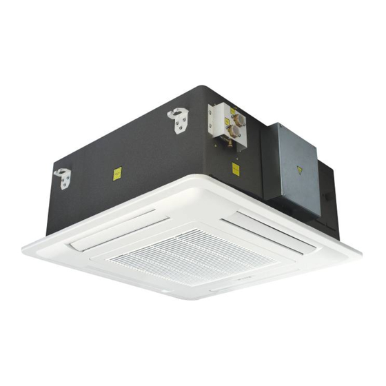
DESCRIPCIÓN DE LA UNIDAD PANEL con diseño atractivo y elegante fabricado en La BATERÍA DE AGUA está fabricada con una ABS. tubería de 3/8” en cobre unida de forma mecánica a aletas de aluminio hidrofílico. Las baterías se prueban en fábrica con aire seco a 30 bars. REJILLA DE SUMINISTRO DE AIRE La superficie interna está... -
Page 5: Mando A Distancia
MANDO A DISTANCIA Ajuste de temperatura Encender/Apagar Modo de funcionamiento Modo sueño Ventilador Rejilla Temporizador de encendido Reloj Cancelar temporizador Temporizador de apagado 1. Ajuste de temperatura: Pulsar los botones de configuración. arriba/abajo para aumentar/disminuir la temperatura 6. Encender/Apagar: Press to switch on or off the configurada. - Page 6 Pantalla LCD del mando a distancia. Instalación de las pilas. El mando a distancia funciona con dos pilas ‘AAA’ 1.5V. Siga los pasos indicados a continuación para instalar o sustituir las pilas. Retire las pilas si el mando a distancia no va a ser usado durante un periodo de tiempo prolongado. Soporte de pared para el mando a distancia.
-
Page 7: Mando De Pared
MANDO DE PARED (OPCIONAL) PANTALLA LCD DEL MANDO DE PARED Temperatura: temperatura configurada o ambiente Modo de funcionamiento Velocidad del ventilador Auto Media Baja Alta Indicación semanal: de domingo a sábado Bloqueo Temporizador Control global maestro en modo de funcionamiento en red Temp. -
Page 8: Botones
FUNCIONAMIENTO DLE MANDO DE PARED IR Receptor de infrarrojos M ODE Pulsar para seleccionar el modo Botón encendido/apagado. Pulsar una vez refrigeración, ventilador, deshumidificación, para arrancar. Volver a pulsar para detener. calefacción o automático (este último solo en unidades de 4 tubos). &... - Page 9 FUNCIONAMIENTO DEL MANDO DE PARED 1) Visualización y configuración del reloj El sistema dispone de un reloj en tiempo real interno y de alta precisión utilizado para la indicación de la hora así como para el temporizador de encendido/apagado. Normalmente, el reloj en tiempo real indica la hora interna, TI M E TI M E que puede ser configurada mediante los botones...
- Page 10 TI M ER 2. Pulse una vez para accede al modo de programación del temporizador. Pulse para seleccionar el día de la semana. A continuación, la unidad maestra recuperará la configuración de la unidad esclava seleccionada y en la zona de visualización del temporizador aparecerá ’rEAd’. La configuración del temporizador de encendido aparecerá...
- Page 11 refrigeración o calefacción. 7) Configuración de temperatura Pulse para acceder al modo de configuración de temperatura. El área de visualización de temperatura parpadeará con la temperatura actual. Pulse el botón superior para ajustar la temperatura. 8) Configuración de modo de funcionamiento M ODE Pulse para cambiar el modo de funcionamiento.
- Page 12 12) Navegación de parámetros C AN C EL Mantener pulsados durante 3 segundos para accede al modo navegación de parámetros. En la pantalla de la unidad aparece la unidad esclava bajo navegación. El método de selección de unidad esclava es idéntico al de control en red.
- Page 13 INSTALACIÓN DEL MANDO DE PARED 1. El mando de pared funciona con una pila de botón de 3V. 2. Abra la cubierta trasera del mando de pared e instale la pila. 3. Preste atención a la dirección de los polos positivo y negativo de la pila. 4.
-
Page 14: Instalación
INSTALACIÓN 1) Comprobación del embalaje 1. Compruebe que el embalaje no ha sufrido daños durante el transporte. 2. Abra el embalaje para comprobar la unidad y los accesorios y anote el número de serie de la unidad. 3. Atención: eleve la unidad sosteniéndola de las esquinas. Nunca eleve la unidad sujetándola por el panel, por tubo de condensados o por las conexiones hidráulicas. - Page 15 4) Lugar de instalación No instale la unidad en ambientes donde haya gases inflamables o alcalinos o bien sustancias ácidas (por ejemplo: cocinas, talleres, etc). El rendimiento de la unidad se verá afectado y los componentes de esta, como las baterías o las piezas de plástico, sufrirán daños irreparables. Si es posible, instale la unidad en el centro de la habitación utilizando para ello un elevador de cargas e insertando una placa contrachapada entre este y la unidad.
- Page 16 6) Conexión de drenaje de condensados La unidad dispone de una bomba de drenaje de condensados que permite una guía de hasta 70 cm desde el nivel del techo. El agua condensada debe eliminarse conectando una manguera de drenaje adecuada al tubo de drenaje del cuerpo de la unidad.
- Page 17 8) Instalación de la bandeja colectora auxiliar externa Inserte el tubo de descarga de agua de la bandeja colectora externa en el orificio preparado en el cuerpo de la unidad. Alinee la posición de ambos tornillos de instalación y coloque la bandeja colectora externa. 9) Conexiones eléctricas Retire la cubierta de la caja de control y observe la etiqueta del diagrama de conexiones situado en la parte trasera de la misma.
- Page 18 11) Conexión para aire fresco/conducto secundario (opcional) Los orificios laterales están dispuestos en la placa lateral del cuerpo de la unidad y disponen de una etiqueta adhesiva que indica su ubicación y uso. La unidad dispone de un orificio lateral para la conexión de un conducto de entrada de aire fresco. La unidad dispone de dos orificios laterales para la conexión de conductos secundarios a fin de descargar el aire tratado en la habitación colindante.
- Page 19 12) Mantenimiento y servicio Desconecte la fuente de alimentación eléctrica antes de realizar cualquier labor de mantenimiento. Empuje y abra los cierres para retirar la rejilla de retorno de aire. Extraiga el filtro de aire y lávelo con agua. Revise el filtro de aire periódicamente. Límpielo y sustitúyalo cuando sea necesario antes de la temporada de uso de la unidad.
-
Page 20: Diagrama De Conexiones
DIAGRAMA DE CONEXIONES UNIDAD BITUBULAR CONFIGURACIÓN DEL PUENTE Puente Corto Abierto Reservado Tipo rejilla para cassette de 4 vías Reservado Unidad bitubular Precalentamiento 30 ºC Precalentamiento 38 ºC Con válvula Sin válvula Modelo Abierto Abierto Refrigeración-Calefacción Abierto Corto Reservado Corto Abierto Solo refrigeración Corto... -
Page 21: Indicadores Luminosos
INDICADORES LUMINOSOS INDICADORES LUMINOSOS LED rojo encendido LED3 (rojo) Unidad en modo de funcionamiento calefacción LED amarillo encendido, temporizador encendido LED2 (amarillo) LED amarillo apagado, temporizador apagado LED verde encendido LED1 (verde) Unidad en modo de funcionamiento refrigeración Botón manual K1 (botón manual) Pulsar para seleccionar el modo de funcionamiento en la siguiente secuencia: refrigeración-calefacción-apagado... -
Page 22: Diagrama De Dimensiones
DIAGRAMA DE DIMENSIONES UNIDAD BITUBULAR Modelo MUCSW-16-HG MUCSW-18-HG MUCSW-21-HG MUCSW-24-HG MUCSW-36-HG MUCSW-42-HG MUCSW-48-HG MUCSW-60-HG 1140 1140 MUCSW-64-HG... - Page 23 NOTAS...
- Page 24 Los datos técnicos incluidos en el presente manual no son vinculantes. El fabricante se reserva todos los derechos a efectuar las modificaciones que estime necesarias para la mejora del producto. La placa de nombre, el diagrama de conexiones y las etiquetas de la unidad prevalecerán sobre el presente manual.
- Page 25 CASSETTE TYPE FAN COIL UNIT MUCSW 4-WAY CASSETTE OPERATION AND INSTALLATION MANUAL 2014 V1.0...
- Page 26 INDEX ITEM CONTENTS PAGE GENERAL INTRODUCTION UNIT DESCRIPTION WIRELESS REMOTE CONTROLLER WIRED REMOTE CONROLLER (WALL PAD) WALL PAD LCD DISPLAY AREA WALL PAD BUTTON WALL PAD OPERATION WALL PAD INSTALLATION INSTALLATION WIRING DIAGRAM LAMP BOARD DISPLAY LAMP BOARD ERROR CODE DISPLAY DIMENSION DRAWING...
-
Page 27: General Introduction
GENERAL INTRODUCTION A fan coil unit is an indoor device consisting of a cooling and/or heating coil and fan. It is terminal unit of a hydronic system. The cassette type fan coil unit is applied for installation in false ceilings. It can be used with chilled or hot water to form an air conditioning system. -
Page 28: Unit Description
UNIT DESCRIPTION PANEL ASSEMBLY with attractive and elegant design WATER COIL manufactured with 3/8” copper by ABS material. tubing mechanically bonded corrugated hydrophilic aluminum fins. Coils shall be factory AIR DELIVERY LOUVER tested by dried air to 30 bars. The internal surface is treated by electrostatic fiber and The coil connections are provided with air bleed with wave shape, efficiently preventing the condensate vent and partial water drain vent. -
Page 29: Wireless Remote Controller
WIRELESS REMOTE CONTROLLER Adjust Set Temperature On/Off Mode Sleep Louver On Timer Clock Cancel Timer Off Timer 1. Adjust Set Temperature: Press down or up button 6. On/Off: Press to switch on or off the unit. decrease increase desired room 7. - Page 30 LCD display area of the wireless remote controller Battery installation The remote handset use two ‘AAA’ 1.5V batteries. Follow above steps to install or replace the batteries. Remove batteries if not used for long period. Wall holder of remote controller Fix the wall holder on the wall by 2 screws.
-
Page 31: Wall Pad Lcd Display Area
WIRED REMOTE CONTROLLER (OPTIONAL) (WALL PAD) WALL PAD LCD DISPLAY AREA Temperature display: display set or room temperature Operation mode display Fan speed display Auto Fan Medium High Display of week: from Sunday to Saturday Key lock Time display area Global control by master in networking mode On Timer Off Timer... -
Page 32: Wall Pad Button
WALL PAD BUTTON IR Infra red reception M ODE Press to select cool, fan, dry, heat or On/off button, press once to start auto-cool-heat operation mode. (Auto mode for operation. Press again to stop operation. 4 pipe system only) & Room temperature setting button Press to select low medium or high speed. -
Page 33: Wall Pad Operation
WALL PAD OPERATION 1) Clock display and setting System has an accurate internal real time clock (RTC) used for time indication and timer ON/OFF function. TI M E TI M E Normally, real time clock display area indicates internal time clock which can be set by button. - Page 34 TI M E TI M E successfully. Press button to change the on timer setting. TI M ER 3. Press button again to enter into off timer programming mode. Press button to select the required day of week. Master unit will then retrieve the setting from the selected slave unit and timer display area will show ‘rEAd’.
- Page 35 9) Fan speed setting Press button to change the fan speed, only low speed available for dehumidification mode. 10) On/Off control Press to start or stop the air conditioner. 11) Networking control (only master unit wall pad can control slave units on the network) Press button to enter into networking control mode.
- Page 36 12) Parameter browsing C AN C EL Hold down buttons for 3 sec to enter into parameters browsing mode. Unit display area shows the slave unit under browsing. Slave unit selection method is the same as in networking control above. Press to browse various parameters as follow: Wall pad display Temp.
-
Page 37: Wall Pad Installation
WALL PAD INSTALLATION 1. There is one 3V button battery supplied together with the wired wall pad. 2. Open the wall pad back cover and install the battery. 3. Pay attention to the battery ‘+’ and ‘-‘ polar direction. 4. Mount the wall pad back cover to the desired location on the wall. 5. -
Page 38: Installation
INSTALLATION 1) Package checking 1. Check the package to ensure no damage during transportation. 2. Open the package to check the unit and accessories, record the unit serial number. 3. Attention: to lift the unit by the four corners of unit body. Do not lift unit by the panel, condensate drain pipe or the water connections. - Page 39 4) Installation location Do not install the unit in rooms where flammable gas or alkaline or acid substance are present (kitchens or workshops etc.). The performance will be affected, and unit components like coils, plastics, etc. will be damaged irreparably. To install unit in the center of room if possible, by using a stacker and inserting a plywood sheet between the unit and the elevated stacker.
- Page 40 6) Condensate drainage connection The unit is equipped with a condensate drainage pump. The pump allows a maximum 70cm head from the level of the suspended ceiling. The condensate water must be eliminated by linking the proper drainage hose with the drain pipe on the unit body.
- Page 41 8) External auxiliary drain pan installation Insert the water delivery tube of the external drain pan into the pre-cut hole on the unit body. Align the 2 installation screw position and fix the external drain pan. 9) Electrical connection Remove control box cover and refer to the wiring diagram label on the back of the cover. The PCB, transformer, motor capacitor, terminal are installed inside the control box.
- Page 42 11) Connection for fresh air/branch duct (optional) The lateral holes are pre-stamped on the side board of unit body, with sticker indicating the location and its usage. There is one lateral hole for fresh air duct connection to intake fresh air. There are two lateral holes for branch duct connection to deliver the treated air to the adjacent room.
- Page 43 12) Maintenance and Service Turn off the main power switch before any operation. Push and unlock the fasteners to open the air return grille. Take out the air filter and wash by water. Check the air filter periodically and before the operating season, to clean or replace while necessary.
-
Page 44: Wiring Diagram
WIRING DIAGRAM 2 PIPE UNIT JUMPER CONFIGURATION Jumper Short Open Reserved Louver type for 4-way cassette Reserved 2 pipe unit Pre-heat 30 degree Pre-heat 38 degree With valve Without valve Model Open Open Cool-Heat Open Short Reserved Short Open Cool only Short Short Reserved... -
Page 45: Lamp Board Display
LAMP BOARD DISPLAY LED DISPLAY Red LED lamp on LED3 (red) Unit under heating operation mode Yellow LED lamp on, Timer on LED2 (yellow) Yellow LED lamp off, Timer off Green LED lamp on LED1 (green) Unit under cooling operation mode Manual touch boutotton K1 (manual touch botton) Press to select the operation model in sequence of... -
Page 46: Dimension Drawing
DIMENSION DRAWING 2 PIPE UNIT Model MUCSW-16-HG MUCSW-18-HG MUCSW-21-HG MUCSW-24-HG MUCSW-36-HG MUCSW-42-HG MUCSW-48-HG MUCSW-60-HG 1140 1140 MUCSW-64-HG... - Page 47 NOTICE...
- Page 48 Technical data shown in this booklet are not binding. The manufacturer shall have the right to introduce at any time whatever modifications deemed necessary to the improvement of the product. The name plate, wiring diagram and notice labels on unit take priority to this brochure...
Need help?
Do you have a question about the MUCSW-16-HG and is the answer not in the manual?
Questions and answers