Table of Contents
Advertisement
Advertisement
Table of Contents

Related Manuals for Denver Instrument DA Series


Summary of Contents for Denver Instrument DA Series
- Page 1 Denver DA Series DA Models Operating Instructions...
-
Page 3: Table Of Contents
Contents Page Safety Precautions ..........4 Getting Started . -
Page 4: Safety Precautions
Safety Precautions Explanation of Symbols: Measurement category This instrument is designed for Caution, risk of danger: measurement category I, with Read the accompanying text a maximum of 8.5V. To ensure carefully. safe operation do not use this instrument for measurements The instrument is double- within the measurement cate- insulated. - Page 5 Repair and maintenance – If you use suction lifting equip- – Repairs are subject to checking ment to lift the load plate, always and can be carried out only at wear gloves, hard-toed safety Denver. In case of defect or func- boots and protective clothing.
- Page 6 Note: – Do not use this equipment in hazardous areas. – Make sure the voltage rating printed on the power supply is identical to your local line voltage. – Use only commercially available batteries (rechargeable or dry-cell battery). If you use a rechargeable battery, use only 12V 2.3AH.
-
Page 7: Getting Started
Getting Started Storage and Shipping Conditions Installation Instructions Do not expose the scale to shocks, The Denver DA scales are designed vibrations, moisture or extreme to provide reliable weighing results temperatures. under normal ambient conditions. When choosing a location to set up Unpacking the Scale your scale, observe the following After unpacking the scale, check... -
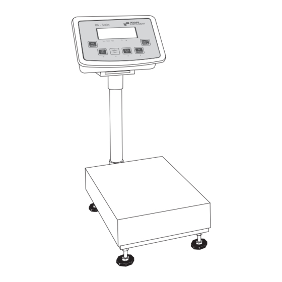
Page 8: General View Of The Equipment
General View of the Equipment 1 Manufacturer’s ID tag 7 Level indicator (option) 2 Housing 8 Leveling feet 9 Stainless steel weighing pan 3 Power cable 4 Display and control unit retainer 10 Power plug 5 Display and control unit column 11 Cable gland cover (for optional 6 Column support foot RS-232 port outlet) -
Page 9: Transport Locking Device
Transport Locking Device – Under the metal frame structure there are four safety overload protection pins. The transportation protection nut is painted red (Note: not on all platform models) Before using the scale, rotate the nut (upwards) until tight. Place the load plate on the scale... -
Page 10: Setting Up The Scale
Setting Up the Scale Connecting Electronic Peripheral Devices § Make absolutely sure to unplug the scale from AC power or switch off (activate battery mode) before you connect or dis- connect a peripheral device (printer or PC) to or from the interface port. Warm-up Time To deliver exact results, the scale must warm up for at least 30 minutes after initial connec-... - Page 11 Assembly Procedure 1. Affix the column bracket with 4 screws 2. Install the column support leveling foot 3. Insert the column into the bracket holder 4. Affix the column with 2 screws 5. Insert the display and control unit retainer into the column 6.
-
Page 12: Operating Design
Operating Design The scales in the DA series consist of Busy Symbol, Plus/Minus Sign a weighing cell and a display and If the symbol displayed here is a diamond b, this indicates that the control unit. In addition to the choice... -
Page 13: Power Management
Power Management Scale connected to AC power: Scale running on battery power: On/Off Switch: On/Off Switch: On: Scale is operational and On: Scale is operational and the display shows function or mode that display shows the function or mode is in use that is in use Off: Depends on menu setting Off: Completely off (no display and... -
Page 14: Descriptions Of The Keys
Descriptions of the Keys 1) On/Off In Battery Mode § Off-Mode: Scale is completely off. “On/off” function will depend on § On-Mode: Scale is in operation different power supply conditions. Use the setup menu for backlight and the display shows the function control and for auto power off. - Page 15 4) Gross-Net/Arrow-Down 6) Print/Enter (Print/Enter) (Gross/Net/Down) Weighing mode: Print key Weighing mode: Function mode: Toggle weight unit gross/net Scroll level up in menu mode/ Counting mode: confirm selected menu. Toggle weight unit gross, net and pcs Function mode: To scroll down menu selection Parameter mode: Reduce digit value by 1 5) Function/Arrow-Up (Fn/Up)
-
Page 16: Configuration (Setup Menu)
Configuration (Setup Menu) To configure the user interface of the scale to individual requirements Step Key (or instruction) Display 1. Switch off the scale 2. Switch on the scale 3. While all the segments are displayed: Press (zero/left arrow) and hold until “1.”... - Page 17 Setup Menu 1. Serial COM 1.1 Baud rate 1.1.1 1.1.2 1,200 1.1.3 2,400 1.1.4 4,800 1.1.5 9,600* 1.1.6 19,200 1.2 Parity 1.2.1 7-bit-None 1.2.2 7-bit-None 1.2.3 7-bit-None 1.2.4 8-bit-None 1.2.5 8-bit-None 1.2.6 8-bit-None 1.3 Print option 1.3.1 Short* 1.3.2 Long/block 1.3.3 Continuous 2.
-
Page 18: Application Programs
Application Programs Counting Step Key (or instruction) Display 1. Select application program (Fn/Up) > 2 sec 2. Select “Counting” (Fn/Up) or (Gross/Net/Down) repeatedly 3. Press Print/Enter. (Print/Enter) Display shows reference piece selection menu. Counting is blinking. 4. Automatically the display will show the reference pieces. -
Page 19: Check Weighing
Check Weighing Step Key (or instruction) Display 1. Select application program (Fn/Up) > 2 sec 2. Select “Checkweighing” (Fn/Up) or (Gross/Net/Down) repeatedly 3. Press Print/Enter to confirm. (Print/Enter) 4. Set lower limit; “LO” flashes. (Fn/Up) or (Gross/Net/Down) and/or (Zero/Left) or (Tare/Right) 5. -
Page 20: Toggling Between Weight Units
Toggling between Weight Units Step Key (or instruction) Display 1. Select application program (Fn/Up) > 2 sec 2. Select “Toggling Weight Units” (Fn/Up) or (Gross/Net/Down) repeatedly 3. Select weight unit 1 (Fn/Up) or (Gross/Net/Down) 4. Confirm weight unit 1 (Print/Enter) 5. -
Page 21: Calibration/Span Adjustment
Calibration/Span Adjustment Calibrate the Scale Step Key (or instruction) Display 1. Switch on the scale 2. Zero the scale (Zero/Left) 3. Select calibration/ (Tare/Right) linearization mode > 2 sec 4. Select calibration (Fn/Up) or (Gross/Net/Down) repeatedly 5. Confirm/start calibration. (Print/Enter) After the zero point is stored, the required calibration weight is displayed... - Page 22 Linearize the Scale Step Key (or instruction) Display 1. Switch on the scale 2. Zero the scale (Zero/Left) 3. Select calibration/ (Tare/Right) linearization mode > 2 sec 4. Select linearization (Fn/Up) or (Gross/Net/Down) repeatedly 5. Confirm/start linearization (Print/Enter) After the zero point is stored, the required linearization weight is displayed.
- Page 23 Step Key (or instruction) Display 10. If the weight is applied within (Print/Enter) the defined time limit and tolerance, the “OK” symbol is displayed. Press “(Print/Enter)” to confirm and save calibration. (To exit linearization, press (Zero/Left) > 2 sec) 11. Remove the linearization weight 12.
-
Page 24: Sbi Interface Protocol Descriptions
SBI Interface Protocol Description Output format with 22 characters The following data block format is output: V W W W W W W W W W U U U CR LF I : ID W : Weight value V : +/– sign U : Unit ID Codes S t a t... -
Page 25: Data Input Formats
Special Codes The data block may contain special information. Special status-dependent codes: 9 10 11 12 13 14 15 16 17 18 19 20 21 22 S1 S2 CR LF The following status codes are output for “S1” and “S2”: : Taring C : Internal calibration - - : All numerals shown in stable readout... - Page 26 The CR and LF characters do not have to be transmitted in the data string. Control Commands ESC P CR LF Print, auto print: initiate / stop ESC T CR LF Zero/Tare – combination ESC V CR LF Zero the weighing platform ESC U CR LF Tare the weighing platform ESC S CR LF...
-
Page 27: Rs-232 Interface Diagram
RS-232 Interface Diagram DB25 DB 9 Diagram for interfacing a computer or different peripheral device to the scale using RS-232 cable length up to 15 m. -
Page 28: Print Formats
Print Formats Printing Mode Options Printing Options Mode of operation Short print Block print (long print) Continuous mode Normal weighing Net weight Gross weight (if tare is active) Gross weight (if tare is not active) mode Tare weight (if tare is active) Net weight Net weight (if tare is active) Counting mode... - Page 29 a. Print Output: b. Sample print outputs in different Expansion of Abbreviations applications Net weight Short printing mode: Gross weight 1.1 Normal weighing Tare weight (appears in block printing mode, if tare is not zero) 1.2 Counting Chk. Checkweighing status 10 pcs (If checkweighing application W.Ref.
- Page 30 2. Block printing mode: Ex 3: If the weight on the pan is between the set limits, 2.1 Normal weighing with zero tare. Ex 1: If tare is zero Chk. Ex 2: If tare is not zero Ex 4: If the weight on the pan >...
- Page 31 Ex 7: If the weight on the pan Continuous printing mode > upper limit set, with tare value set. Normal weighing Ex 1: If tare is not active Chk. Ex 2 : If tare value is present. Counting mode 2.4 Unit toggling default: 2 Pcs Ex 1: Before toggle key is...
-
Page 32: Error Codes
Error Codes Error codes are shown on the main display. “Err“ codes are shown continuously; “Inf.“ messages are shown for 2 seconds, after which the program returns automatically to the weighing mode. Problem Cause Solution Nothing appears No power available Check the power supply or some symbols The AC adapter is not... - Page 33 Problem Cause Solution Fatal error Contact customer service FEErr Err 54 No platform is connected Connect a platform or sensor Err 55 Max. Weighing The scale was switched Place the weighing pan on capacity is less on without the weighing pan the scale and press “On/Off”...
-
Page 34: Care & Maintenance
Care and Maintenance Cleaning Corrosive Environment Unplug the scale from the Remove all traces of corrosive sub- AC power before cleaning. stances from the weighing platform To clean the weighing platform: on a regular basis. use a piece of cloth, wet with a commercially available cleaning Safety Inspection agent (IPA –... - Page 35 Instructions for Recycling the Packaging To ensure safe shipment, your scale has been packaged using environ- mentally friendly materials. After successful installation of the scale, you should return this packaging for recycling. For information on recycling options, including recycling of old weighing equipment, contact your municipal waste disposal center or local recycling depot.
-
Page 36: Specifications
Specifications No. of keys Display LCD, 6 digits, character height: 25 mm, 7-segment with backlight (amber) Functions 1. Zero, 2. Tare, 3. Counting, 4. Checkweighing, 5. Net/gross weight, 6. Toggle between weight units, 7. Auto power off (optional battery mode) Maximum readability 15000d Temperature range... -
Page 37: Accessories (Options)
Specifications of the Individual Models: Model Capacity Resolution Platform size Column Height DA6EDP-L0-US 6 kg 0.5 g 400 x 300 mm 500 mm DA15EDP-L0-US 15 kg 400 x 300 mm 500 mm DA30EDP-L0-US 30 kg 400 x 300 mm 500 mm DA60EDP-L0-US 60 kg 400 x 300 mm... -
Page 38: C Marking
C Marking The scale complies with the Directive 2006/95/EC: following EC Directives and European “Electrical equipment designed for Standards: use within certain voltage limits” Directive 2004/108/EC: Applicable European Standards: “Electromagnetic compatibility (EMC)” EN 61010 Safety requirements for electrical EN 61326-1 measurement, control, and laboratory Electrical equipment for measure- equipment... - Page 40 Denver Instrument. The status of the information, specifications and illustrations in this manual is indicated by the date given below. Denver Instrument reserves the right to make changes to the technology, features, specifications, and design of the equipment without notice.
Need help?
Do you have a question about the DA Series and is the answer not in the manual?
Questions and answers