IBM 6266 User Manual
Hide thumbs
Also See for 6266:
- Benutzerhandbuch (166 pages) ,
- Manual do utilizador (160 pages) ,
- Guías del usuario manual (160 pages)
Table of Contents
Advertisement
Quick Links
Advertisement
Table of Contents

Related Manuals for IBM 6266


Summary of Contents for IBM 6266
-
Page 1: User Guide
Personal Computer Types 6266, 6270 and 6276 User Guide... - Page 2 © Copyright International Business Machines Corporation 2000. All rights reserved. Note to U.S. Government Users – Documentation related to restricted rights – Use, duplication or disclosure is subject to restrictions set forth in GSA ADP Schedule Contract with IBM Corp.
-
Page 3: Table Of Contents
Content Notices vii Safety information ..................viii Installation .....................viii Safety while working with hardware............ix Lithium battery notice ................xi Regulatory safety notice for the CD-ROM and DVD-ROM drive ..xi Laser compliance statement ..............xii Consignes de sécurité ................xiii Consignes de sécurité lors de la manipulation du matériel ....xiv About this book ..................1-1 About this book ....................1-1 Where to find more information ..............1-3... - Page 4 Opening the system unit ................5-5 Taking safety precautions ..............5-5 Removing the top cover for type 6266 ..........5-6 Removing the top cover for type 6270 and 6276 ........5-7 Looking inside the system unit for type 6266 ..........5-9...
- Page 5 For adapter cards .................6-16 For Drives .....................6-16 Adding and replacing system board components ........7-1 Identifying system board parts (type 6266, 6270 and 6276) ......7-2 PCI Card connector and jumper information ..........7-4 Identifying adapter card connectors ............7-4 Setting a jumper ..................7-4 Upgrading the system memory ..............7-5...
- Page 6 Solving modem problems ..............8-15 Error codes and messages ................8-17 IBM Diagnostic Programs ................8-20 Appendix A. Specification tables ............... A-1 Memory module placement ................A-1 Memory map ....................A-2 System input/output addresses ..............A-3 System interrupts ..................A-5 DMA channel assignments ................
-
Page 7: Notices
Web sites. The materials at those Web sites are not part of the materials for this IBM product and use of those Web sites is at your own risk. -
Page 8: Safety Information
The construction of the IBM Personal Computer provides extra protection against the risk of electrical shock. The IBM computer has a power cord with a three-prong plug that is required to ground metal parts. It is the responsibility of the person installing the computer to connect it to a properly grounded electrical outlet. -
Page 9: Safety While Working With Hardware
Safety while working with hardware Each time you open your computer, you must follow specific safety procedures to ensure that you do not damage your computer. For your safety, and the safety of your equipment, follow the steps for “Disconnecting your computer” on page x before you remove the cover of the system unit (if included with the model you purchased). -
Page 10: Modem Safety Information
• Avoid using a telephone (other than a cordless type) during an electrical storm. There may be a remote risk of electric shock from lightning. • Do not use the telephone to report a gas leak in the vicinity of the leak. IBM Personal Computer User Guide... -
Page 11: Lithium Battery Notice
Lithium battery notice Your computer uses lithium batteries. There may be Caution! a risk of fire, explosion, or burns if the batteries are handled incorrectly. To ensure safety: • Do not recharge, disassemble, heat, or incinerate a lithium battery. • Replace the battery with an identical or equivalent type lithium battery. •... -
Page 12: Laser Compliance Statement
Laser compliance statement Some IBM Personal Computer models are equipped from the factory with a CD- ROM or DVD-ROM drive. CD-ROM/DVD-ROM drives are also sold separately as options. The CD-ROM/DVD-ROM drive is a laser product. The CD-ROM/DVD-ROM drive is certified in the U.S. to conform to the requirements of the Department of Health and Human Services 21 Code of Federal Regulations (DHHS 21 CFR) Subchapter J for Class 1 laser products. -
Page 13: Consignes De Sécurité
Consignes de sécurité Installation La conception de fabrication de l'ordinateur personnel IBM assure une protection accrue contre les risques d'électrocution. Le PC IBM possède un cordon d'alimentation équipé d'une fiche à trois broches qui permet une mise à la terre des principaux éléments métalliques de la machine. -
Page 14: Consignes De Sécurité Lors De La Manipulation Du Matériel
5. Mettez l’ordinateur sous tension ainsi que tout périphérique connecté disposant d’un interrupteur d’alimentation. Débranchement de l'ordinateur. Pour débrancher l'ordinateur, procédez comme suit: 1. Mettez l'ordinateur hors tension ainsi que tout périphérique connecté disposant d'un interrupteur d'alimentation. IBM Personal Computer User Guide... - Page 15 2. Débranchez tous les cordons d'alimentation des prises de courant. 3. Débranchez tous les câbles (câble de téléphone, par exemple) de leurs prises. 4. Débranchez tous câbles de l’ordinateur (les cordons d’alimentation, les câbles d’entrée-sortie et tous les autres câbles qui pourraient y être connectés).
- Page 16 à un rayonnement laser de niveau supérieur à la classe 1 dans des conditions normales d’utilisation. Veuillez noter qu’aucune pièce de l’unité de CD-ROM n’est réglable ni réparable. Ne confiez la réparation de cette unité qu’à une personne qualifiée. IBM Personal Computer User Guide...
- Page 17 Conformité aux normes relatives aux appareils laser. Certains modèles d’ordinateurs personnels sont équipés d’origine d’une unité de CD-ROM ou de DVD-ROM. Mais ces unités sont également vendues séparément en tant qu’options. L’unité de CD-ROM/DVD-ROM est un appareil à laser. Aux Etat- Unis, l’unité...
- Page 18 IBM Personal Computer User Guide...
-
Page 19: About This Book
Chapter 1. About this book The User Guide contains general information for all users of an IBM Personal Computer. Once you have taken your computer out of the box and connected all the components, you can use this book as a guide to your computer's hardware and as a problem-solving tool. - Page 20 Windows DOS box prompt. • “Appendix C. Monitor terminology” on page C-1 This appendix contains definitions of some of the terms generally used to describe monitor characteristics. IBM Personal Computer User Guide...
-
Page 21: Where To Find More Information
Online Information: The “online information” is available within Access IBM and also from IBM via the WWW. See your Quick Reference for more about accessing IBM information on the WWW. Your computer comes with different types of online documentation. The software that came preinstalled on your computer may include online tutorials and exercises that can help you learn how to use your computer. - Page 22 IBM Personal Computer User Guide...
-
Page 23: Getting Started
Chapter 2. Getting started This chapter contains the following sections to help you make adjustments and connections to your computer. • “Controlling monitor settings” on page 2-2 • “Controlling volume” on page 2-6 • “Setting up communications” on page 2-9 •... -
Page 24: Controlling Monitor Settings
• Under some conditions, interference patterns, such as curved, shadowy lines can occur. If these patterns appear on your screen, change your software program's background color or design. • To extend the life of your monitor, turn it off at the end of each day. IBM Personal Computer User Guide... -
Page 25: Power Saver Feature
Power saver feature Your monitor documentation should indicate whether your monitor has a power saver feature. This feature may be called Display Power Management Signaling (DPMS). With DPMS, the monitor's display goes blank if you have not used your computer for a predetermined period of time. To redisplay the screen, press the shift key on your keyboard or move the mouse. - Page 26 The highest resolution and color settings are not always best. For example: • Higher resolutions display more pels (picture elements). While this allows more text and graphics to be displayed, it makes them appear smaller. For most IBM Personal Computer User Guide...
- Page 27 users, 640x480 or 800x600 is a comfortable resolution setting. • When you select more colors, most software programs will slow down. Choose only as many colors as you need. • You can determine which settings are most comfortable to work with by selecting and trying each one.
-
Page 28: Controlling Volume
Volume Control. This method starts the master Volume Control window, which allows you to adjust the volume of each audio device individually. If no sound comes from your speakers, you might have the volume set too low or the mute function activated. IBM Personal Computer User Guide... -
Page 29: Adjusting The Headphone Volume
(not available on all systems) or into the line-out jack on the back of the computer’s system unit. The line-out jack is marked with the icon • On some IBM computers, a headphone jack and a volume control are located on the CD-ROM drive on the front of the computer’s system unit. - Page 30 Note: program on your computer. You cannot control the headphone volume from the volume control on the CD-ROM drive. IBM Personal Computer User Guide...
-
Page 31: Setting Up Communications
Refer to sections “Opening the system unit” on page 5-5 and “Adding and removing adapter cards for type 6266” on page 6-4 for instructions. Before your computer can use its modem, you must complete the procedures in the following sections: •... -
Page 32: Configuring Your Communications Software
See “Modem commands” on page B-5 for information about typing AT commands in a Windows Terminal program or a Windows DOS box. If you need more information about modems, see “Modems features” on page B-1. 2-10 IBM Personal Computer User Guide... -
Page 33: Configuring Your Computer For A Connection To The Internet
Configuring your computer for a connection to the Internet If your computer is equipped with a modem, you can connect to the Internet. Before you configure your Internet software, you must first connect your computer to a telephone network. Your computer comes with a software selection CD. You can use Netscape Navigator by loading the software selection CD.To install Netscape Navigator, click on the Netscape icon on the desktop and follow the instructions on the screen. -
Page 34: Using The Rapid Access Ii Keyboard
(Mute, Volume, and CD/DVD controls); these cannot be changed. There are 104 keybuttons for Rapid Access Keyboard. Among the easy keybuttons, the Internet, Internet Shopping, IBM Web support, World Book, Option and Help keybuttons are preset to start certain programs on your computer. The preset functions are printed on the label above the keybuttons. -
Page 35: Power Management Features
Chapter 3. Power management features Your computer is compliant to ACPI (Advance Control Power Interface) and the APM (Advance Power Management) functions. It will enter a power-saving mode according to the power management option you specify. You can set up the power management option in the Configuration/Setup Utility. See “Power Management Setup”... -
Page 36: Acpi Bios Mode
4. Press Esc to return to the Configuration/Setup Utility menu. 5. Before you exit from the program, select Save Settings from the Configuration/Setup Utility menu. 6. To exit from the Configuration/Setup Utility menu, press Esc and follow the instructions on the screen. IBM Personal Computer User Guide... -
Page 37: Apm
This feature allows the computer to save power through monitoring your computer’s hardware. Follow these steps to use the APM feature: 1. Start the Configuration/Setup Utility (see “Configuration/Setup Utility overview” on page 4-2.) 2. Select Power Management from the Configuration/Setup Utility menu 3. -
Page 38: Automatic Power On
5. Press Esc to return to the Configuration/Setup Utility menu. 6. Before you exit from the program, select Save Settings from the Configuration/Setup Utility menu. 7. To exit from the Configuration/Setup Utility menu, press Esc and follow the instructions on the screen. IBM Personal Computer User Guide... -
Page 39: Bios Setup Configuration
Chapter 4. BIOS Setup configuration Your IBM Personal Computer is already configured for immediate use. You can view your computer’s configuration settings using the Configuration/Setup Utility. You can also use these configuration utilities to change some configuration settings. For example, if you add or replace hardware inside your system unit, you might need to verify or update specific settings. -
Page 40: Configuration/Setup Utility Overview
Some of the parameters and related settings in Setup are for reference only, such as those items in the System Summary and Product Data menus. Refer to the section “Viewing system information and product data” on page 4-6 for details on these menus. IBM Personal Computer User Guide... - Page 41 The configurable options allow you to control how your computer operates. For example, you can use Setup to: • Configure hard disk, CD-ROM, or any other IDE drives • Select and configure I/O devices, such as serial, parallel, USB, and video devices •...
-
Page 42: Entering Setup
2. Turn on the computer and display. 3. When you see the IBM logo and the line message “Press F1 to enter Setup”, press F1 to enter Setup and display the Configuration/Setup Utility menu. You cannot enter Setup after the Power On Self Test Note: (POST) is complete. -
Page 43: Working With The Setup Menus
Working with the Setup menus The Configuration/Setup Utility menu appears immediately after you press F1. Configuration/Setup Utility menu The Configuration/Setup Utility menu that you see on Note: your computer may look slightly different from the menu shown here, but the options will operate just the same. The Configuration/Setup Utility menu lists system configuration options. -
Page 44: Viewing System Information And Product Data
To view other computer information such as the model number, serial number, and BIOS version and date, select the Product Data option from the Configuration/ Setup Utility menu. Like in the System Information menu, the items displayed are not configurable. IBM Personal Computer User Guide... -
Page 45: Changing Parameter Settings
Loading the default settings When you purchase an IBM personal computer, it is already configured for use. The original configuration settings, also called factory or default settings , are stored in the CMOS. Setup includes an option, Load Default Settings, that lets you reload the original configuration at any time. -
Page 46: Canceling Changes
1. From the Configuration/Setup Utility menu, select Save and Exit Setup. Then, press Enter. 2. A dialog box appears saying "Save to CMOS and EXIT (Y/N)?” Type Y, and then press Enter. The computer restarts using the new settings. IBM Personal Computer User Guide... -
Page 47: Setup Parameters
Setup parameters Devices and I/O Ports Use the options in this menu to configure the devices and I/O ports in this computer. Mouse This setting allows you to select whether or not a mouse is installed. Diskette Drive A Use this setting to define the type of drive installed as drive A. None No floppy drive installed 720K, 3.5 in... -
Page 48: Ide Drives Setup
Palette snooping. Video Interrupt Select enabled if you are using an application that requires this support. Audio support Use this setting to enable or disable the Audio function if your computer has the audio feature. 4-10 IBM Personal Computer User Guide... -
Page 49: Start Options
Network setup Use this setting to enable or disable the Network function. Start Options The start options are settings that affect the way your computer acts when started. Startup Sequence Your computer can be started from several devices, including the hard disk drive, diskette drive, and CD-ROM drive. - Page 50 This setting allows you to determine whether or not logos are displayed during the power on sequence. Network Boot F12 Option This setting allows you to boot from Network after the system is turned on by pressing F12. 4-12 IBM Personal Computer User Guide...
-
Page 51: Date And Time
Date and Time Use this setting to set the date and time of the internal clock in your computer. Advanced Setup You can use these features to configure advanced hardware features. Do not attempt to change these settings unless you have an advanced technical knowledge of computer hardware. -
Page 52: Isa Legacy Resources
ACPI BIOS Mode is enabled. This setting allows automatic power saving through monitoring of your computer’s hardware. APM BIOS Mode Enable this setting to reduce power consumption during periods of hardware inactivity. 4-14 IBM Personal Computer User Guide... -
Page 53: System Security
Activity Monitor Use this setting to set up the system activities that you want monitored for automatic power management Automatic Power On Use this setting to define automated methods of waking up the computer: • Wake up when the modem senses an incoming ring •... -
Page 54: Remote Administration
If Yes, the keyboard will be locked during adapter ROM initiation. this can be used in conjunction with an administrator password to prevent the use of adapter ROM based on utilities. Refer to “System Security” on page 4-15 for details on setting a system password and setup password. 4-16 IBM Personal Computer User Guide... -
Page 55: Using Other Configuration Utilities
Using other configuration utilities You can use Setup to view or change configuration settings for most of your factory- installed hardware. If you install new hardware, however, you might need to use other configuration utilities. When you purchase new hardware to install in your computer, a configuration utility or new drivers may come with the new hardware. - Page 56 4-18 IBM Personal Computer User Guide...
-
Page 57: Preparing To Upgrade
• “Resolving resource conflicts” on page 5-4 • “Opening the system unit” on page 5-5 • “Looking inside the system unit for type 6266” on page 5-9 • “Looking inside the system unit for type 6270 and 6276” on page 5-11... -
Page 58: Evaluating Your New Hardware
If you receive an error message, use the Windows Device Manager to reassign system resources. See the section “Using the Windows Device Manager” on page 5-4 for instructions. Refer also to “Appendix A. Specification tables” on page A-1. IBM Personal Computer User Guide... -
Page 59: Planning Your Hardware Changes
Planning your hardware changes You should understand how your new hardware will work with your existing hardware before you unplug your system unit, pull the cover off, and start removing or adding hardware. You should also record your changes as you work. Make sure that you have read the preceding section “Evaluating your new hardware”... -
Page 60: Resolving Resource Conflicts
5. Select a device item, then click on the Properties button. A display box appears showing the properties of the device. 6. Make the necessary changes in the settings that will not conflict with other devices. 7. Click on OK. IBM Personal Computer User Guide... -
Page 61: Opening The System Unit
Opening the system unit Each time you open your system unit, you must follow specific safety procedures to ensure that you do not damage your computer. Taking safety precautions Before you open the system unit, review ”Safety information” on page viii. For your safety and the safety of your equipment, follow these steps before you remove the system unit cover: 1. -
Page 62: Removing The Top Cover For Type 6266
Removing the top cover for type 6266 Follow these steps to remove the system unit top cover: 1. Remove the screw that secures the top cover at the back of the system unit. 2. Hold both sides of the system unit top cover and push it forward about 0.25 inch. -
Page 63: Removing The Top Cover For Type 6270 And 6276
Removing the top cover for type 6270 and 6276 Follow these steps to remove the system unit top cover: See “Taking safety precautions” on page 5-5 to Note: disconnect the cables before you perform the following steps. 1. Remove the three screws that secure the top cover at the back of the system unit. - Page 64 3. Touch the bare metal frame of your system unit to dissipate the static electricity from your body. Do not touch any of the components inside the frame before you touch the frame. Do not touch any of the components that have a voltage warning label. IBM Personal Computer User Guide...
-
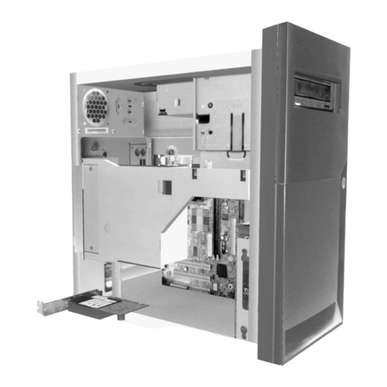
Page 65: Looking Inside The System Unit For Type 6266
Looking inside the system unit for type 6266 After you remove the system unit top, the system unit looks like the following figure. Note: See the next page for a description of the hardware components inside the system unit. Your computer has three bays. One bay is for 5.25-inch drive and two bays are for 3.5-inch drives. - Page 66 Bay 2. This drive can accommodate a 3.5-inch device. In many models, this bay holds a factory-installed hard disk drive. Bay 1. This drive bay can accommodate a 3.5-inch slim IDE hard disk. In many models, this bay holds a factory-installed diskette drive. 5-10 IBM Personal Computer User Guide...
-
Page 67: Looking Inside The System Unit For Type 6270 And 6276
Looking inside the system unit for type 6270 and 6276 After you remove the system unit top, the system unit looks like the following figure. Note: See the next page for a description of the hardware components inside the system unit. Your computer has four bays that can hold up to two 5.25-inch drives and two 3.5- inch drives. - Page 68 3.5-inch to 5.25-inch installation kit. Bay 1. This drive bay can accommodate a 5.25-inch half-high drive such as a diskette, hard disk, tape, or CD-ROM. In many models, this bay holds a factory-installed CD-ROM drive. 5-12 IBM Personal Computer User Guide...
-
Page 69: Adding And Removing Adapter Cards And Drives
Chapter 6. Adding and removing adapter cards and drives Before you begin working with the hardware inside your system unit, read the following sections: • “Evaluating your new hardware” on page 5-2 This section contains the information you need to understand about potential system resource conflicts. -
Page 70: Resolving Conflicts With Installed Adapter Cards
6. In the Modem Properties window, click on the Resources tab. If you need help in using the Device Manager, press the F1 key to view the online help. You must restart your computer before any Device Manager changes can take effect. IBM Personal Computer User Guide... -
Page 71: Working With The Hardware In The System Unit
To add or remove adapter cards or drives in the system unit, complete the instructions in the following sections: • “Adding and removing adapter cards for type 6266” on page 6-4 • “Adding and removing adapter cards for type 6270 and 6276” on page 6-5 •... -
Page 72: Adding And Removing Adapter Cards For Type 6266
Adding and removing adapter cards for type 6266 The system board includes three PCI adapter card connectors (only the low-profile PCI cards will fit). Make sure that you have followed the proper procedure in “Opening the system unit” on page 5-5. -
Page 73: Adding And Removing Adapter Cards For Type 6270 And 6276
Adding and removing adapter cards for type 6270 and 6276 The system board includes three PCI adapter card connectors. Make sure that you have followed the proper procedure in “Opening the system unit” on page 5-5. Note: This ensures that you discharge the static electricity that you may have accumulated. -
Page 74: Removing And Adding Drives
CD-ROM drives), while the third connector is for diskette interface drives (such as diskette drives or tape drives). If the type of your system is 6266, 6270 or 6276, use the following illustration to identify the signal cable connectors on your system board:... - Page 75 The hard disk that came installed in your computer is attached to IDE connector 1 and is set as a master device. If your computer came with a CD-ROM drive, it is attached to IDE connector 2 and is set as a master device. These are the general guidelines for IDE/ATA signal cable connections: •...
- Page 76 See “BIOS Setup configuration” on page 4-1 for details. When you have finished installing the diskette drive, enter Setup to make sure that the drive parameter setting is correct. See “Loading the default settings” on page 4- IBM Personal Computer User Guide...
- Page 77 Removing the diskette drive for type 6266 If you want to replace or remove the diskette drive, do the following: 1. Disconnect the power and signal cables from the rear of the diskette drive. 2. Pull up the latch that secures the drive mounting tray.
-
Page 78: Removing The Diskette Drive For Type 6270 And 6276
If you want to replace the diskette drive, you must follow these steps: 1. On the back of the system, remove the screw that secures the power supply. 2. Pull the latch on the drive mounting tray and the power supply upward to remove it completely. 6-10 IBM Personal Computer User Guide... - Page 79 3. Disconnect the power and signal cables from the back of the diskette drive. 4. Remove the two screws that hold the diskette drive to the mounting tray. 5. Open the door on the front of the computer. 6. Pull the diskette drive toward the front of the computer to remove it. 7.
-
Page 80: Removing The Cd-Rom Drive For Type 6266
Removing the CD-ROM drive for type 6266 To replace the CD-ROM, do as follows: 1. Disconnect the power, sound and signal cables from the CD-ROM. 2. Pull up the latch that secures the CD-ROM drive mounting tray. 3. Slide the CD-ROM drive mounting tray to the front of the computer and remove the tray. -
Page 81: Removing The Cd-Rom Drive For Type 6270 And 6276
Removing the CD-ROM drive for type 6270 and 6276 To replace the CD-ROM: 1. Disconnect the power, sound and signal cables from the CD-ROM. 2. Remove the screws that secure the CD-ROM drive . 3. Open the door on the front of the computer. 4. -
Page 82: Removing The Hard Disk Drive For Type 6266
Removing the hard disk drive for type 6266 To replace or remove the hard disk drive, follow these steps: 1. Follow the above steps to remove the CD-ROM. 2. Make sure to disconnect the power cord and signal cables from the hard disk drive and the diskette drive. -
Page 83: Removing The Hard Disk Drive For Type 6270 And 6276
Removing the hard disk drive for type 6270 and 6276 To replace or remove the hard disk drive, do the following: 1. Disconnect the power and signal cables from the diskette drive. 2. Lay the computer on the side to access the screws on the bottom. Remove the two screws that secure the mounting tray at the bottom of the system unit. -
Page 84: Updating The Cmos Settings In Setup
Select Devices and I/O Ports from the “Configuration/Setup Utility overview” on page 4-2 to verify drive settings. Normally, BIOS will auto-detect the HDD and CD-ROM drive at the POST stage and show them on the screen. 6-16 IBM Personal Computer User Guide... -
Page 85: Adding And Replacing System Board Components
The following sections contain instructions for working with the hardware components on your system board: • “Identifying system board parts (type 6266, 6270 and 6276)” on page 7-2 • “PCI Card connector and jumper information” on page 7-4 • “Upgrading the system memory” on page 7-5 •... -
Page 86: Identifying System Board Parts (Type 6266, 6270 And 6276)
If you plan to add or replace hardware in your computer, you need to know the layout of the system board. This figure shows an example of the system board of the type 6266, 6270 and 6276 in your computer. The items on the next page correspond to the numbered locations on the figure. - Page 87 The system board, sometimes called the planar or motherboard, is the main circuit board in the system unit. It supports a variety of devices and provides other basic computer functions that are preinstalled or that you can install later. The system board shown on the previous page has the following parts: Fan power connector (CPUFAN).
-
Page 88: Pci Card Connector And Jumper Information
PCI adapter card measuring 120 mm in length (or less) Refer to the section “Adding and removing adapter cards for type 6266” on page 6- 4 and “Adding and removing adapter cards for type 6270 and 6276” on page 6-5 for instructions on adding or removing cards. -
Page 89: Upgrading The System Memory
Upgrading the system memory Your system board has two system memory module sockets: DIMM 0, and DIMM 1. These sockets hold Dual Inline Memory Modules (DIMMs) that contain 3.3V single- or double-sided synchronous DRAM (SDRAM). You can install up to a maximum of 256 MB of system memory into these sockets. -
Page 90: Removing Memory Modules
To remove a DIMM, pivot the retaining clips on both sides of the socket outward to release the DIMM. Verifying the system memory To view the system memory settings in Setup, select System Summary from the Configuration/Setup Utility menu. IBM Personal Computer User Guide... -
Page 91: Replacing The System Battery
Replacing the system battery Follow these steps to replace the battery: Before replacing the lithium battery review the lithium battery notice on “Lithium battery Note: notice” on page xi. 1. Note the orientation of the battery in the bracket. 2. Press outward on the mental latch and lift the battery out. 3. - Page 92 2. Double-click on the Control Panel icon. 3. From the Control Panel, double-click on the Date/TIme icon to display the items for changing the date and time. 4. Make the necessary changes then click on the OK button. IBM Personal Computer User Guide...
-
Page 93: Updating The Cmos Settings In Setup
Updating the CMOS settings in Setup When you add system board components, such as system memory modules, your system's Basic Input/Output System (BIOS) detects the hardware changes and updates the CMOS settings automatically. However, if you replace or remove components, you might receive a message that asks you to verify if the automatic detection changed the configuration correctly. - Page 94 7-10 IBM Personal Computer User Guide...
-
Page 95: Diagnosing And Recovering From Problems
• “Error codes and messages” on page 8-17 This section lists the BIOS error codes and messages and their respective corrective actions. • “IBM Diagnostic Programs” on page 8-20 This section tells you how to recover your computer if your computer is damaged. -
Page 96: Before You Panic: Some Simple Fixes
If you are using a multiple outlet device (for example, a power surge protector or power strip), make sure it is plugged in and turned on. If the problem continues, refer to the “Quick problem solving chart” on page 8-6. IBM Personal Computer User Guide... - Page 97 Step 2 Did the system unit beep after it was turned on? There is a problem with the system unit. Find the Yes, more than once error code or message in the section “Error codes and messages” on page 8-17 and take the action listed.
- Page 98 2. If the monitor you attached is a VGA monitor and not an SVGA monitor (older monitors may be VGA), detach the VGA monitor and attach an SVGA monitor. Using an SVGA monitor allows your computer system to take full advantage of Windows video function. IBM Personal Computer User Guide...
- Page 99 Step 3 Is anything displayed on the monitor? (Continued) • The colors displayed are wrong. Make sure the monitor cable is correctly and securely connected to the system unit. If the problem continues, refer to “Solving hardware and software problems” on page 8-7 and take the action listed. •...
-
Page 100: Quick Problem Solving Chart
8-7. If thi s d oes no t fix th e u p po rt In f o rm ati on sectio n p ro b lem , s ee the S u p po rt In f o rm ati on sectio n IBM Personal Computer User Guide... -
Page 101: Solving Hardware And Software Problems
“Installing memory modules” on page 7-5. For instructions on installing adapter cards in your system unit, see “Adding and removing adapter cards for type 6266” on page 6-4 and “Adding and removing adapter cards for type 6270 and 6276” on page 6-5. - Page 102 5. Double click on CD-ROM and select the listed CD- ROM option. 6. Click on the Settings tab. 7. Under Options, click on Auto insert notification (a check appears in the box). 8. Click on OK. IBM Personal Computer User Guide...
- Page 103 Table 1: Hardware problems (Continued) If the problem is: Here's what to do: Can’t write to diskette 1. Make sure you are using the correct type of diskette. Make sure that the diskette is correctly formatted. 2. Make sure the diskette is not write-protected. 3.
- Page 104 Reconnect the mouse cable to the system unit. g. Turn on the computer. 8. Turn the system unit off, wait 10 seconds, and then turn the system unit on again. 8-10 IBM Personal Computer User Guide...
- Page 105 7. Make sure the modem adapter card is installed correctly. For instructions on installing adapter cards in the system unit, see “Adding and removing adapter cards for type 6266” on page 6-4 and “Adding and removing adapter cards for type 6270 and 6276” on page 6-5.
- Page 106 Integrated Peripherals menu in Setup. 9. Make sure the parallel port Operation Mode parameter is set to a mode that matches your printer. 10.For additional help, see the user's guide that came with the printer. 8-12 IBM Personal Computer User Guide...
-
Page 107: Solving Software Problems
The most common cause for the clock losing time is related to application programs, not a hardware failure. If you experience this problem, do the following: 1. From the Windows desktop, click on the IBM Update Connector icon to obtain the latest software updates for your computer. - Page 108 See “About your software” that comes with your computer. Power Button Override < 4 sec. under the Setup Power Management menu and the system does not turn off when you press the power button for more than four seconds. 8-14 IBM Personal Computer User Guide...
-
Page 109: Solving Modem Problems
If you cannot resolve the problem after reading this section, contact your IBM PC HelpCenter for assistance. Table 3: Modem problems... - Page 110 2. Make sure the RTS/CTS hardware flow control is terminal emulation mode is enabled (do not use XON/XOFF software flow control). being used by your 3. Make sure the data speed is not faster than your software computer's capability. 8-16 IBM Personal Computer User Guide...
-
Page 111: Error Codes And Messages
Error codes and messages When you see error codes and messages on your screen, find the error code or message in the following table, then take the applicable corrective action or actions. Table 4: Error codes and messages Error codes Error messages Corrective actions CMOS battery failed... - Page 112 Secondary slave hard disk fail 1. Load the default settings in Setup. 2. Check the IDE drive jumper. 3. Check the power to the IDE drive. 4. Check the IDE cable/connection. 5. Check the IDE drive. 8-18 IBM Personal Computer User Guide...
- Page 113 Table 4: Error codes and messages (Continued) Error codes Error messages Corrective actions 8602 PS/2 Mouse error OR no PS/2 1. Determine if the mouse is connected mouse present properly and is defined correctly in BIOS Setup. Diagnosing and recovering from problems 8-19...
-
Page 114: Ibm Diagnostic Programs
Doctor for Windows help system. Product Recovery Program Your IBM computer has a Product Recovery Program, which is a recovery image on the hard disk drive accessed by pressing F11 during startup. For more information about the Product Recovery Program, see the Quick Reference that comes with your computer. -
Page 115: Appendix A. Specification Tables
This memory module placement table shows you how to place dual inline Memory modules (DIMMs) into the sockets labelled DIMM1 Bank 0 and DIMM Bank 1. Refer to the section “Identifying system board parts (type 6266, 6270 and 6276)” on page 7-2 for the location of the DIMM sockets. -
Page 116: Memory Map
960~1024 KB (0F0000 ~ 0FFFFF) System BIOS memory (100000 ~ Upper Limit) Main memory (Upper Limit ~ 4 GB) PCI memory Upper Limit means the maximum size of installed Note: memory. The Main Memory Maximum size is 512 MB. IBM Personal Computer User Guide... -
Page 117: System Input/Output Addresses
System input/output addresses This table shows the hexadecimal addresses for each of the system board Input/ Output (I/O) functions. You may want to use this information if you install an adapter card that requires you to set I/O addresses. Table 3: System input/output addresses Address range Function (hexadecimal) - Page 118 Table 3: System input/output addresses (Continued) Address range Function (hexadecimal) 3F7-3F7 Primary EIDE 3F8-3FF Serial Asynchronous Port 1 0CF8 Configuration Address Register 0CFC Configuration Data Register 778-77A Parallel Printer Port 1 IBM Personal Computer User Guide...
-
Page 119: System Interrupts
System interrupts This table shows the system Interrupt Requests (IRQs) and their functions. You may use this information if you install an adapter card that requires you to set IRQs. In some cases, the device listed uses the IRQ. Table 4: System interrupts Interrupt Function request (IRQ) -
Page 120: Dma Channel Assignments
I/O devices to transfer data directly to and from memory. You may need to select an available DMA channel if you add an I/O device that uses DMA. Table 5: DMA channel assignments DMA channel Assignment Available Audio Floppy Diskette Printer Port Cascade Available Available Available IBM Personal Computer User Guide... -
Page 121: Serial Port Addresses
Serial port addresses IBM computers have a built-in external serial port already installed in the computer. The connector for this port is located at the back of your computer. This port can be used to connect a serial mouse, serial printer, or other serial device and to transfer data between computers. -
Page 122: Connector Functions
Connector functions The following table includes the specific functions of the connectors. Refer to the section “Identifying system board parts (type 6266, 6270 and 6276)” on page 7-2 for an illustration of the connector locations. Table 7: Connector functions Connector... -
Page 123: Appendix B. Modem Information
Some IBM computers have a modem already installed. If your computer came with a modem, all you have to do is connect the modem to a telephone line. (You may also connect a telephone to the modem if it has two RJ11C jacks). The system firmware is already configured to load the modem drivers and software once you have made the connections. - Page 124 • IS-101 voice command set • V.42bis (data compression) • V.42 (error correction) • MNP5 (data compression) • TIA/EIA 602 AT command set • V.8 start-up sequence • MNP2-4 error correction • Personal Computer 99 logo IBM Personal Computer User Guide...
-
Page 125: Operating Your Modem
Operating your modem You can perform common modem functions such as dialing, file transfer, and faxing using the modem communications software that came with your computer. For information about configuring communications software, “Configuring your communications software” on page 2-10 It is still possible for you to perform the basic modem functions using the AT commands from the Windows DOS box prompt. -
Page 126: Disabling Call Waiting
Call Waiting. For specific instructions, see the user's guide or online Help that came with the communications software. If your computer came with a fax software already installed, use the fax software documentation included in your computer package or the fax software online help for additional information. IBM Personal Computer User Guide... -
Page 127: Modem Commands
Modem commands This section provides information on the modem commands if you operate your modem from the DOS prompt using the AT command strings. Executing commands Your modem is in the Command Mode when powered-on and is ready to receive and execute AT commands. -
Page 128: At Commands
;= return to command mode after dialing Commands echo disabled Commands echo enabled Escape characters - switch from data mode to command mode Modem on-hook (hang-up) Modem off-hook (make busy) Firmware and device ID Checksum code IBM Personal Computer User Guide... - Page 129 Table1: AT commands (Continued) Command Function ROM test Firmware and device ID Low speaker volume Low speaker volume Medium speaker volume High speaker volume Speaker always off Speaker on until carrier detected Speaker always on Return to data mode Initiate an equalizer retrain and return to data mode Pulse dial Result codes enabled Result codes disabled...
- Page 130 Same as X0 plus all CONNECT responses/blind dialing Same as X1 plus dial tone detection Same as X1 plus busy signal detection/blind dialing All responses and dial tone and busy signal detection Reset and recall user profile IBM Personal Computer User Guide...
-
Page 131: Detail For +Ms Controls
Detail for +MS Controls Table 2: Detail for +MS Controls +MS=<carrier>,<automode>,<min transmit rate>,<max transmit rate>,<min receive rate>,<max receive rate> <carrier>= B103 for Bell 103 (300 bps) B212 for Bell 212 (1200 bps) V21 for V.21 (300 bps) V22 for V.22 (1200 bps) V22B for V.22bis (1200-2400 bps) V23C for V.23 V32 for V.32 (4800 &... -
Page 132: Extended At Commands
Modem hangs up and returns to the command mode after DTR toggle &F Load factory default configuration &G0 Guard tone disabled &G1 550 Hz guard tone enabled &G2 1800 Hz guard tone enabled &V View active profiles B-10 IBM Personal Computer User Guide... -
Page 133: V.42Bis Commands
V.42bis commands Table 4: V.42bis commands Command Function +IFC = 0,0 Disable flow control +IFC = 2,2 Enable RTS/CTS hardware flow control (data mode default) +IFC = 1,1 Enable XON/OFF software flow control +DS = 0,0,2048,32 Data compression disable +DS =3,0,2048,32 V.42bis/MNP5 data compression enabled +ES = 0,0,1 Normal mode (speed buffering) only... -
Page 134: Modem Response Codes
No answer The line being called did not answer within the time-out period Connect xxxx Connected at 2400 bps Delayed Dialing delayed Blacklisted Number is blacklisted Fax connection Data Data connection +FC error Fax error B-12 IBM Personal Computer User Guide... -
Page 135: S Registers
S registers S registers are information storage areas inside the modem. The AT command set uses the S registers to configure modem options. Some S registers have default settings. For normal modem operations, the default settings are usually adequate. However, special circumstances may require you to change some defaults. To change or read the value of an S register, begin the command with the letters AT. - Page 136 Comma pause time 0-255 /seconds Carrier loss time 1-255 /10ths of a second Touch-tone dialing speed 50-255 /milliseconds Escape character detect time 0-255 /50ths of a second Flash dial modifier time 0-255 /10 milliseconds B-14 IBM Personal Computer User Guide...
-
Page 137: Appendix C. Monitor Terminology
Appendix C. Monitor terminology As you read the documentation that came with your monitor and the monitor information provided in this chapter, you might find a few technical terms. If you change your monitor settings, refer to the following table to understand some of the terms used to describe monitor characteristics. - Page 138 IBM Personal Computer User Guide...
-
Page 139: Index
Configuration/Setup Utility, See Setup connector 1 4-9 conflicts 8-2 connector 2 4-9 Internet 2-11 connecting through the IBM Global disk drives 4-11, 4-7, 4-11 Network 2-11 adding and removing 4-8 connecting through the Internet connectors on the system board 4-... - Page 140 connecting to the telephone net- Setup work 2-9 default settings modems B-1 loading 4-7 auto-answer feature B-3 entering 4-4 monitor exiting 4-8 controlling settings 2-2 main menu 4-5 display mode C-1 menu information 4-2 display properties 2-3 moving through menus 4-5 selecting 2-4, 2-5 parameters display settings 2-3...
- Page 141 volume controlling 2-6 Windows Device Manager 5-4...
- Page 144 Part Number: 06P8708...
Need help?
Do you have a question about the 6266 and is the answer not in the manual?
Questions and answers