Table of Contents
Advertisement
Quick Links
IM10123
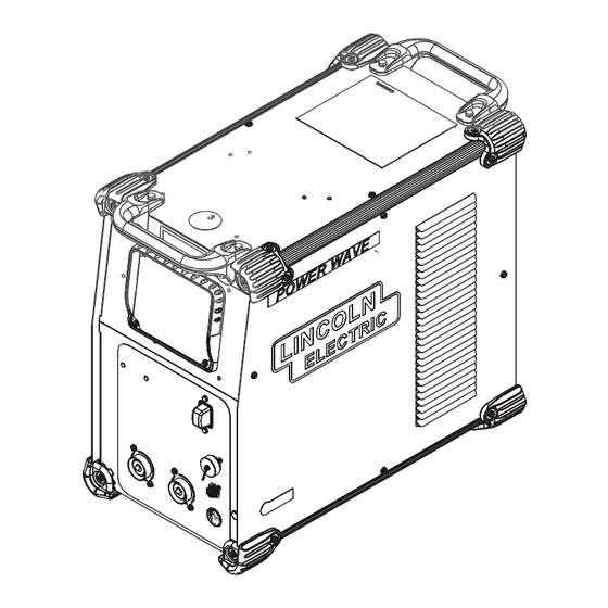
POWER WAVE S500CE
®
September, 2012
11883
For use with machines having Code Numbers:
Safety Depends on You
Lincoln arc welding and cutting
equipment is designed and built
with safety in mind. However,
your overall safety can be
increased by proper installation
... and thoughtful operation on
your part. DO NOT INSTALL,
OPERATE OR REPAIR THIS
EQUIPMENT WITHOUT READ-
ING THIS MANUAL AND THE
SAFETY PRECAUTIONS CON-
TAINED THROUGHOUT. And,
most importantly, think before
you act and be careful.
OPERATORʼS MANUAL
Copyright © Lincoln Global Inc.
• World's Leader in Welding and Cutting Products •
• Sales and Service through Subsidiaries and Distributors Worldwide •
Cleveland, Ohio 44117-1199 U.S.A.
TEL: 1.216.481.8100
For Service in U.S. and Canada: Call 1.888.935.3877
FAX: 1.216.486.1751
WEB SITE: lincolnelectric.com
For Non-U.S. Service: Email globalservice@lincolnelectric.com
Advertisement
Table of Contents

Related Manuals for Lincoln Electric POWER WAVE S500CE IM10123


Summary of Contents for Lincoln Electric POWER WAVE S500CE IM10123
- Page 1 IM10123 POWER WAVE S500CE ® September, 2012 11883 For use with machines having Code Numbers: Safety Depends on You Lincoln arc welding and cutting equipment is designed and built with safety in mind. However, your overall safety can be increased by proper installation ...
-
Page 2: California Proposition 65 Warnings
351040, Miami, Florida 33135 or CSA Standard W117.2-1974. A Free copy of “Arc Welding Safety” booklet E205 is available from the Lincoln Electric Company, 22801 St. Clair Avenue, Cleveland, Ohio 44117-1199. BE SURE THAT ALL INSTALLATION, OPERATION, MAINTENANCE AND REPAIR PROCEDURES ARE PERFORMED ONLY BY QUALIFIED INDIVIDUALS. -
Page 3: Electric Shock Can Kill
SAFETY ARC RAYS can burn. ELECTRIC SHOCK can 4.a. Use a shield with the proper filter and cover kill. plates to protect your eyes from sparks and 3.a. The electrode and work (or ground) circuits the rays of the arc when welding or observing are electrically “hot”... - Page 4 SAFETY WELDING and CUTTING CYLINDER may explode SPARKS can if damaged. cause fire or explosion. 7.a. Use only compressed gas cylinders 6.a. Remove fire hazards from the welding area. containing the correct shielding gas for the If this is not possible, cover them to prevent process used and properly operating the welding sparks from starting a fire.
- Page 5 SAFETY 5. Toujours porter des lunettes de sécurité dans la zone de PRÉCAUTIONS DE SÛRETÉ soudage. Utiliser des lunettes avec écrans lateraux dans les zones où lʼon pique le laitier. Pour votre propre protection lire et observer toutes les instructions et les précautions de sûreté...
- Page 6 2004/108/EC. It was manufactured in conformity with a national standard that implements a harmonized standard: EN 60974-10 Electromagnetic Compatibility (EMC) Product Standard for Arc Welding Equipment. It is for use with other Lincoln Electric equipment. It is designed for industrial and professional use. Introduction All electrical equipment generates small amounts of electromagnetic emission.
- Page 7 SAFETY Electromagnetic Compatibility (EMC) The size of the surrounding area to be considered will depend on the structure of the building and other activities that are taking place. The surrounding area may extend beyond the boundaries of the premises. Methods of Reducing Emissions Public Supply System Welding equipment should be connected to the public supply system according to the manufacturer’s rec- ommendations.
- Page 8 Electric for advice or information about their use of our products. We respond to our customers based on the best information in our posses- sion at that time. Lincoln Electric is not in a position to warrant or guarantee such advice, and assumes no liability, with respect to such infor- mation or advice.
-
Page 9: Table Of Contents
viii viii TABLE OF CONTENTS Page Installation........................Section A Technical Specifications ....................A-1, A-2 Safety Precautions .......................A-3 Location, Lifting ......................A-3 Stacking ........................A-3 Tilting..........................A-3 Input and Ground Connections ..................A-3 Machine Grounding .......................A-3 High Frequency Protection....................A-3 Input Connection ........................A-4 Input Fuse and Supply Wire ..................A-4 Input Voltage Selection ....................A-4 Connection Diagram ..................A-5, A-6, A-7 Recommended Work Cable Sizes ................A-8... -
Page 10: Installation
INSTALLATION TECHNICAL SPECIFICATIONS - POWER WAVE ® S500CE POWER SOURCE-INPUT VOLTAGE AND CURRENT Model Duty Cycle Input Voltage ± 10% Input Amperes Idle Power Power Factor @ Rated Output 40% rating 230/400*460/575 67/41/34/27 K3168-1 50/60 Hz 300 Watts Max. (includes 380V to 415V) (fan on) 100% rating 50/30/25/20... - Page 11 INSTALLATION WELDING PROCESS PROCESS OUTPUT RANGE (AMPERES) OCV (U Mean Peak GMAW GMAW-Pulse 40-550A 100V FCAW GTAW-DC 5-550A 15-550A SMAW PHYSICAL DIMENSIONS DEPTH WEIGHT MODEL HEIGHT WIDTH 24.80in ( 630mm) 150 lbs (68 kg) 14.00in ( 356 mm) 22.45 in ( 570 mm) K3168-1 TEMPERATURE RANGES OPERATING TEMPERATURE RANGE...
-
Page 12: Safety Precautions
INSTALLATION LIFTING SAFETY PRECAUTIONS Read this Both handles should be used when lifting POWER entire installation section before you start installa- ® WAVE S500CE. When using a crane or overhead tion. device a lifting strap should be connected to both WARNING ®... -
Page 13: Input Connection
INSTALLATION INPUT FUSE AND SUPPLY WIRE WARNING CONSIDERATIONS Only a qualified electrician should Refer to Specification Section for recommended fuse, connect the input leads to the wire sizes and type of the copper wires. Fuse the POWER WAVE ® S500CE. input circuit with the recommended super lag fuse or Connections should be made in delay type breakers (also called "inverse time"... -
Page 14: Connection Diagram
INSTALLATION CONNECTION DIAGRAMS GTAW (TIG) WELDING TIG welding from a LF-45 wire feeder can be used with the power source as shown in (Figure A.2), SMAW (STICK) WELDING FIGURE A.2 REGULATOR ARCLINK FLOWMETER + POSITIVE BACK CONNECTIONS ON LF-45 ARCLINK GAS HOSE POWER WAVE S500 CE... -
Page 15: Power Wave
INSTALLATION SMAW (STICK) WELDING Stick welding from a LF-45 wire feeder can be used with the power source as shown in (Figure A.3). FIGURE A.3 ARCLINK BACK + POSITIVE CONNECTIONS ON LF-45 ARCLINK ® POWER WAVE S500 CE + POSITIVE - WORK (PART OF K2394-1) K857-2 REMOTE... - Page 16 INSTALLATION GMAW (MIG) WELDING MIG welding from a LF-45 wire feeder can be used with the power source as shown in (Figure A.4). FIGURE A4 REGULATOR FLOWMETER ARCLINK BACK CONNECTIONS ON + POSITIVE LF-45 ARCLINK GAS HOSE ® POWER WAVE S500 CE + POSITIVE K940-XX...
-
Page 17: Recommended Work Cable Sizes
INSTALLATION RECOMMENDED WORK CABLE General Guidelines SIZES FOR ARC WELDING • Select the appropriate size cables per the Connect the electrode and work cables between the “Output Cable Guidelines” below. Excessive volt- appropriate output studs of the POWER WAVE ® age drops caused by undersized welding cables and poor connections often result in unsatisfactory weld- S500CE per the following guidelines:... -
Page 18: Cable Inductance And Its Effects On Welding
INSTALLATION Depending upon the process, inductance within the CABLE INDUCTANCE AND ITS electrode and work cables can influence the voltage EFFECTS ON WELDING apparent at the studs of the welder, and have a dra- matic effect on performance. Remote voltage sense leads are used to improve the accuracy of the arc volt- Excessive cable inductance will cause the welding age information supplied to the control pc board. - Page 19 A-10 A-10 INSTALLATION Electrode Voltage Sensing The remote ELECTRODE sense lead (67) is built into the 5-pin arclink control cable (K1543-xx) and is always connected to the wire drive feed plate when a wire feeder is present. Enabling or disabling electrode voltage sensing is application specific, and automati- cally configured by the active weld mode.
-
Page 20: Voltage Sensing Considerations For Multiple Arc Systems
A-11 A-11 INSTALLATION VOLTAGE SENSING If Sense Leads ARE Used: CONSIDERATIONS FOR MULTIPLE • Position the sense leads out of the path of the weld ARC SYSTEMS current. Especially any current paths common to adjacent arcs. Current from adjacent arcs can induce voltage into each others current paths that Special care must be taken when more than one arc can be misinterpreted by the power sources, and... - Page 21 A-12 A-12 INSTALLATION • For circumferential applications, connect all work leads on one side of the weld joint, and all of the work voltage sense leads on the opposite side, such that they are out of the current path. (See Figure A.7) FIGURE A.7 POWER SOURCE...
-
Page 22: Control Cable Connections
A-13 A-13 INSTALLATION CONTROL CABLE CONNECTIONS Connection Between Power Source and Ethernet Networks General Guidelines The POWER WAVE S500CE is equipped with an ® IP67 rated ODVA compliant RJ-45 Ethernet connec- Genuine Lincoln control cables should be used at all tor, which is located on the rear panel. -
Page 23: Operation
OPERATION GRAPHIC SYMBOLS THAT APPEAR ON SAFETY PRECAUTIONS THIS MACHINE OR IN THIS MANUAL READ AND UNDERSTAND ENTIRE SECTION BEFORE OPERATING MACHINE. WARNING OR WARNING CAUTION • ELECTRIC SHOCK CAN KILL. • Do not touch electrically live part or electrode with skin or DANGEROUS wet clothing. -
Page 24: Product Description
OPERATION PROCESS LIMITATIONS PRODUCT DESCRIPTION The software based weld tables of the POWER PRODUCT SUMMARY WAVE ® S500CE limit the process capability within the The POWER WAVE S500CE is a portable multi- ® output range and the safe limits of the machine. In process power source with high-end functionality general the processes will be limited to .030-.052 solid capable of Stick, DC TIG, MIG, Pulsed MIG and Flux-... -
Page 25: Design Features
OPERATION CASE FRONT CONTROLS DESIGN FEATURES (See Figure B.1) Loaded with Standard Features 1. USER INTERFACE (OPTIONAL) • Multiple process DC output range: 5 - 550 Amps. 2. STATUS LED - (See Troubleshooting Section for operational functions) • 200 – 600 VAC, 3 phase, 50-60Hz input power. 3. -
Page 26: Case Back Controls
OPERATION CASE BACK CONTROLS (See Figure B.2) 1. ETHERNET 2. GAS INLET (OPTIONAL) 3. RESERVED FOR FUTURE DEVELOPMENT 4. SYNC TANDEM (OPTIONAL) 5. REAR ARCLINK (OPTIONAL) 6. DEVICENET (OPTIONAL) 7. COOLER OUTPUT POWER PANEL (OPTIONAL) 8. INPUT POWER CORD 9. CIRCUIT BREAKER FIGURE B.2 POWER WAVE S500CE... -
Page 27: Common Welding Procedures
Many variables al, electrode size, and shielding gas. For a more com- beyond the control of The Lincoln Electric plete description of the weld modes programmed into Company affect the results obtained in applying... - Page 28 OPERATION SMAW (STICK) WELDING The nominal preprogrammed voltage is the best aver- The welding current and Arc Force settings can be set age voltage for a given wire feed speed, but may be through a Power Feed 10M or Power Feed ™...
- Page 29 OPERATION Most pulse welding programs are synergic. As the wire feed speed is adjusted, the POWER WAVE ® S500CE will automatically recalculate the waveform parameters to maintain similar arc properties. The POWER WAVE S500CE utilizes “adaptive con- ® trol” to compensate for changes in the electrical stick- out while welding.
-
Page 30: Accessories
ACCESSORIES KITS, OPTIONS AND ACCESSORIES Dual Cylinder Kit Permits side-by-side mounting of two full size gas All Kits Options and Accessories are found on the cylinders, with easy loading. For use with K1764-1 Web site: (www.lincolnelectric.com) cart. Order K1702-1 FACTORY INSTALLED None Available Coaxial Welding Cable Optimum weld cables for minimizing cable inductance... - Page 31 ACCESSORIES STICK OPTIONS Foot Amptrol® Provides 25 ft. (7.6 m) of remote ACCESSORY KIT - 150 Amp current control for TIG welding. (6- For stick welding. Includes 20 ft. pin plug connection). (6.1m) #6 electrode cable with lug, Order K870 15 ft.
-
Page 32: Maintenance
MAINTENANCE SAFETY PRECAUTIONS WARNING ELECTRIC SHOCK can kill. • Do not operate with covers removed. • Turn off power source before installing or servicing. • Do not touch electrically hot parts. • Turn the input power to the welding power source off at the fuse box before working in the terminal strip. -
Page 33: Troubleshooting
HOW TO USE TROUBLESHOOTING GUIDE WARNING Service and Repair should only be performed by Lincoln Electric Factory Trained Personnel. Unauthorized repairs performed on this equipment may result in danger to the technician and machine operator and will invalidate your factory warranty. For your safety and to avoid Electrical Shock, please observe all safety notes and precautions detailed throughout this manual. - Page 34 TROUBLESHOOTING USING THE STATUS LED TO Included in this section is information about the Status Lights and some basic troubleshooting charts for both TROUBLESHOOT SYSTEM PROBLEMS machine and weld performance. The status light for the main control board and input control Not all of the POWER WAVE ®...
- Page 35 TROUBLESHOOTING Observe all Safety Guidelines detailed throughout this manual ERROR CODES FOR THE POWER WAVE S500CE ® The following is a partial list of possible error codes for the POWER WAVE ® S500CE. For a complete listing con- sult the Service Manual for this machine. MAIN CONTROL BOARD ( “STATUS”...
- Page 36 TROUBLESHOOTING Observe all Safety Guidelines detailed throughout this manual INPUT CONTROL BOARD Error Code # Indication Type Instantaneous input current limit has been exceeded. Typically 331 Instantaneous Input Current indicates short term power overload. If problem persists contact Limit Service Department. Persistent Input current limit was exceeded during machine power-up.
- Page 37 3. Contact your local authorized 3. Major physical or electrical dam- Lincoln Electric Field Service age is evident when the covers facility for technical assistance. are removed. 1. Make sure input supply discon- Machine will not power up (no lights) 1.
- Page 38 TROUBLESHOOTING Observe all Safety Guidelines detailed throughout this manual PROBLEMS POSSIBLE RECOMMENDED (SYMPTOMS) CAUSE COURSE OF ACTION Thermal LED is ON Improper fan operation Basic Machine Problems (Continued) 1. Check for proper fan operation. Thermal LED is ON 1. Improper fan operation. Fan should run in a low speed setting when the machine is idle and in a high speed when the...
- Page 39 TROUBLESHOOTING Observe all Safety Guidelines detailed throughout this manual PROBLEMS POSSIBLE RECOMMENDED (SYMPTOMS) CAUSE COURSE OF ACTION Weld and Arc Quality Problems (Continued) Wire burns back to tip at the end of 1. Burnback Time 1. Reduce burnback time and/or the weld.
- Page 40 TROUBLESHOOTING Observe all Safety Guidelines detailed throughout this manual PROBLEMS POSSIBLE RECOMMENDED (SYMPTOMS) CAUSE COURSE OF ACTION Ethernet Cannot Connect 1. Physical connection. 1. Verify that the correct patch cable or cross over cable is being used (refer to local IT department for assistance).
- Page 41 DIAGRAMS POWER WAVE S500CE ®...
- Page 42 DIMENSION PRINT POWER WAVE S500CE ®...
- Page 43 Do not touch electrically live parts or Keep flammable materials away. Wear eye, ear and body protection. WARNING electrode with skin or wet clothing. Insulate yourself from work and ground. Spanish No toque las partes o los electrodos Mantenga el material combustible Protéjase los ojos, los oídos y el AVISO DE bajo carga con la piel o ropa moja-...
- Page 44 Keep your head out of fumes. Turn power off before servicing. Do not operate with panel open or WARNING Use ventilation or exhaust to guards off. remove fumes from breathing zone. Spanish Los humos fuera de la zona de res- Desconectar el cable de ali- No operar con panel abierto o AVISO DE...
- Page 45 Need Help? Lincoln Electric “Rapid Response” Service! Call 1.888.935.3877 to talk to a Service Representative Hours of Operation: 8:00 A.M. to 6:00 P.M. (ET) Mon. thru Fri. After hours? Use “Ask the Experts” at lincolnelectric.com A Lincoln Service Representative will contact you by the next business day.
Need help?
Do you have a question about the POWER WAVE S500CE IM10123 and is the answer not in the manual?
Questions and answers