Dometic RMD 8501 Installation Instructions Manual
Absorption refrigerator for recreation vehicles
Hide thumbs
Also See for RMD 8501:
- Operating instructions manual (60 pages) ,
- Installation instructions manual (24 pages) ,
- Service instructions manual (50 pages)

Related Manuals for Dometic RMD 8501


Summary of Contents for Dometic RMD 8501
-
Page 1: Installation Instructions
Installation Instructions Absorption Refrigerator for Recreation Vehicles RMD 8501 RMD 8505 RMD 8551 RMD 8555 AUS / NZ MBA 06/2012 N 1-1 Type C40 / 110 289 0318 - 29... -
Page 2: Table Of Contents
Wiring diagrams ..............© Dometic GmbH - 2012 - Subject to change without notice... -
Page 3: Unpacking And Transport
WARNING! DO NOT USE A FLAME TO CHECK FOR GAS 0.0 Unpacking and transport Lifting / carrying the refrigerator CAUTION! Never use for lifting or carrying other parts of the refrigerator (i.e. cooling unit, gas pipe) ! The refrigerator will be damaged ! -
Page 4: General
(used without the safety alert sym- No part of these instructions may be reprodu- bol) indicates a potentially hazardous situation ced, copied or utilised in any other way wit- which, if not avoided, may result in damage to the appliance. hout written authorisation by Dometic. -
Page 5: Warranty
Dometic reserves the right to make rator. changes at any time which are deemed to be in the interest of improving the product and Environmental Tips safety. -
Page 6: Safety Instructions
Safety instructions 2.0 Safety instructions Application according to DANGER! regulations Never use an unshielded flame to check This appliance is designed for storage of food gas bearing parts and pipes for leakage! and storage of frozen food and making ice. The refrigerators outlined herein have been There is a danger of fire or explosion.. -
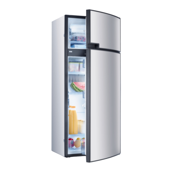
Page 7: Description Of Model
Description of model 3.0 Description of model Refrigerator rating plate Model identification Example : The rating plate is to be found on the inside of the refrigerator. It contains all important details 8 5 0 1 of the refrigerator. You can read off from this the model identification, the product number and the serial number. -
Page 8: Technical Data
24hrs 160 lit. 30 lit. 190 W / 170 W ca.3,2 KWh / 380 g 40 kg • RMD 8501 1245x523x567 160 lit. 30 lit. 190 W / 170 W ca.3,2 KWh / 380 g 40 kg •... -
Page 9: Installation Instructions
If the door/grille distance is between 25 mm The electrical installation must comply and 45 mm, we recommend installing a with national and local regulations. Dometic ventilation kit to achieve an optimal cooling performance in high ambient tempera- Electrical wiring regulations tures. -
Page 10: Rear Installation
NOT provided. attach to the refrigerator ! Dometic strongly recommends carrying this Attach the deflector plate so that the heated out using a flexible seal (in order to simplify air escapes through the top ventilation grill into... -
Page 11: Ventilation And Air Extraction Of The Refrigerator
The ventilation grilles must have an open cross-section of at least 450 cm². This is achieved by using the Dometic LS300 / L500 absorber ventilation and air extraction system which has been tested and approved for this purpose. -
Page 12: Installation With Roof Exhaust R500 And Lower Vetnilation Grille Ls300
Installation Installation of lower and upper ventilation 4.3 Installing the ventilation system grilles LS300. 4.3.1 Installation LS300 or L500 (NZ) To install the ventilation grilles cut two rectan- gles to suit in the outer wall of the vehicle (for position of the cuts, see Fig. 13). LS300 L500 Cut two rectangles in the... -
Page 13: Installing The Ventilation System
Installation Exhaust duct system The exhaust gas duct system must be made in Please be aware that the L 500 vent grille is such a manner as to achieve a complete equipped with locking screws instead of sli- extraction of combustion products to the out- ders. -
Page 14: Installation Recess
Ensure that the refrigerator is installed level in the recess. Fig. 21 4.5.2 Recess dimensions CAUTION! Models RMD 8501 Always insert screws through the sleeves RMD 8505 provided as otherwise components laid in RMD 8551 foam, such as cables etc., could be dama- RMD 8555 ged. -
Page 15: Insert The Decor Panel
Installation Frameless decor panel Insert the decor panel Decor panel with frame Remove the lateral ledge (1) from the door (ledge attached, screwed). Shift decor panel (2) away from the door and insert the new decor panel. Re-attach ledge (1). Fig. -
Page 16: Gas Installation
Installation correct method of operation. In case the Gas installation appliance fails to operate correctly after all checks have been carried out, refer to the aut- horised service provider in your area. WARNING! The gas connection shall be carried out Gas connection by specialised personnel* only. -
Page 17: Electrical Installation
Where a socket outlet with mains supply is used, the outlet must be freely accessible. Should the connection cable be damaged, have it replaced by Dometic Customer Services or by qualified personnel to avoid hazards. -
Page 18: Terminal Strip
Installation 4.9.4 Cable connections 4.9.3 D+ and solar connection (only for AES models) D+ signal connection For MES and AES it is compulsory to provi- In >Automatic Mode< the AES electronic de a permanent 12V DC supply at the termi- system automatically selects the most efficient nals C/D (permanent voltage supply for energy supply. - Page 19 Installation Contacts at the electronics : INput heating element (12 V DC) OUTput heating element (12 V DC) Earth Fig. 33 ® Plug-in contacts (manufacturer: Stocko MF 9562-002-80E MF 9562-002-8 OC 3-pin with D+ contact: MF 9562-003-8 30 960-000-00 2-pin : MF 9562-002-8 ON + spade connector 6.3 x 0.8 MKH 5132-1-0-200...
-
Page 20: Wiring Diagrams
Installation 4.9.5 Circuit diagrams Circuit diagram RMD 85x1, RMD 85x5 Fig. 34 = 12V OUT / 12 V power supply for optional connections For MES and AES it is compulsory to provide CAUTION! a permanent 12V DC supply at the terminals Under no circumstances can this perma- C/D (permanent voltage supply for functional nent DC supply be 24 V. - Page 21 Installation Fan (optional) RMD 85x1, RMD 85x5 Fig. 35...
- Page 24 www.dometic.com...
Need help?
Do you have a question about the RMD 8501 and is the answer not in the manual?
Questions and answers