
Related Manuals for Foto Walser walimex pro VC-200 PLUS

Summary of Contents for Foto Walser walimex pro VC-200 PLUS
- Page 1 Copy of Instruction Manual Gewerbering 26 86666 Burgheim Tel. +49 84 32 / 9489-0 Fax. +49 84 32 / 9489 - 8333 eMail: info@foto-walser.de Studio Flash www.foto-walser.de Series VC-200 PLUS to VC-1000 PLUS...
-
Page 2: Table Of Contents
21. Technical specifications ..............32 Content 22. Overview about operation panel............ 33 How to understand the instruction manual ........3 1.1.Markings on the device ..............3 1.2.Markings in this manual ............... 4 Important safety notes ..............4 Unpack and check the device ............8 Operation of the device.............. -
Page 3: How To Understand The Instruction Manual
Thank you very much for your confidence. We wish you much pleasure and 1.2. Markings in this manual success with your studio flash. The walimex pro Studio Flash series VC PLUS is Marking Meaning especially developed for ambitious beginners and professional users. The VC PLUS series is perfectly suitable for studio, portrait, person, nude and Indicates the handling and consequences of safety product photography. - Page 4 − Make sure, that cables and conductors won´t be damaged. Damages Make sure, that the device is always positioned tilt and skid resistant and stored securely. could be caused through heat impact, chemical influence or through − Keep out of reach of children and animal. They could overturn the mechanical impacts as rubbing, bending, tearing, rolling over or nibbling animals.
-
Page 5: Unpack And Check The Device
− Please handle the modeling lamp and flash tube with care to avoid WARNING Fire danger through overheating bursting. − Don´t touch the flash tube with bare hands. Wear clean cotton gloves or The device can overheat, if you operate it with mounted protection cap or with covered ventilation slots. -
Page 6: Operation Of The Device
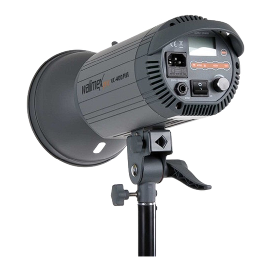
4.3. Quick start guide Operation of ft heevice ADVICE: 4.1. Overview about the parts The detailed instruction for the following operations can be found in the Reflector respective chapters in this instruction manual. Unlocking Lever Keep the sequences of the following operation steps when using the device Photo Cell (hidden) for the first time to avoid damages on the device. -
Page 7: Demount And Mount Protection Cap
Demount and mount protection cap Mount and demount reflector WARNING WARNING Posterior danger of bursting of flash tube Posterior danger of bursting of flash tube Make sure not to touch the flash tube with bare hands accidentally. Make sure not to touch the flash tube with bare hands accidentally. Openings for reflector or protection cap Openings for reflector and protection 1.mount protection cap:... -
Page 8: Screw In And Out Of Modeling Lamp
2. Demount reflector: 3. Let the device cool down. WARNING! Danger of burning on reflector, modeling lamp and flash WARNING! Danger of burning on reflector, modeling lamp and flash tube. Please let the device cool down for approx. 30 minutes. tube. -
Page 9: Adjustments
2. Switch on device: 10. Adjustments Set main switch on I (ON). • The digital display shows the current adjusted flash output. 10.1. Adjust flash output • The display lights up and shows READY when the adjusted flash output You can adjust the power of the flashes according to the below mentioned is reached. -
Page 10: Adjust The Modeling Lamp Depending On Flash Output
1. Switch on device. 6. The modeling lamp switches on. • The signal MODEL lights up. See Switch the device on and off. 2. Turn control button OUTPUT POWER until the digital display shows the 7. Press push-button MODEL or push-button MODEL until the desired output. -
Page 11: Prepare And Adjust Flash Trigger
3. Switch off photo cell: 10.5. Prepare and adjust flash trigger Press push-button SLAVE until the signals SLAVE 1, SLAVE 2 and SLAVE 3 go out. Prepare flash trigger through camera Switch on, adjust and switch off pre-flash suppression ADVICE: Please note the user information of the camera manufacturer for flash 1. -
Page 12: Mount Reflex Umbrella (Optional)
6. Let the device cool down. Locking Lever WARNING! Danger of burning on reflector, modeling lamp and flash tube. Please cool down approx. 30 minutes. Locking Knurl Tripod Mount 7. Open locking knurl. 8. Insert the rod of reflex umbrella through the opening in the reflector into the fixture as far as it will go. -
Page 13: Trigger The Flash
o Don´t trigger a flash during the 15 minutes cooling time, neither 14. Trigger the flash with reduced flash output. WARNING o Switch off the modeling lamp. Fire danger through overheating. See Switch on and off of modeling lamp. • When the signal warning of overheating and overloading beeps: Continuous rapid sequences of flashes from more than 8 flashes per minute Reduce the flash output or flash sequence. -
Page 14: Solve Problems
Switch off the device for Disconnect from power supply during cleaning. output approx. 30 minutes. Danger of overloading Internal voltage Switch on/off the flash. If inside the flash is too you still have the defect, high contact the Foto Walser service department... - Page 15 1. Discharge device: Part of ft heevice Cleaning WARNING! Danger of electric shock. Discharge the device before Housing Use a microfiber cloth to remove light and changing the flash tube. stubborn dirt. • Switch on device. Modeling bulb, flash Wipe off with dust brush or dry, soft cloth See Switch the device on and off.
-
Page 16: Accessories And Options
ADVICE: 4. Pull out the fuse holder with your hands completely out of ft helot. Press the two plug-in contacts carefully and even into the socket as to 5. Take out the old micro-fuse. avoid the deformation of the wires. 6. -
Page 17: Spare Parts
19. Spare parts 21. Technical specifications VC-200 VC-300 VC-400 VC-600 VC-800 VC-1000 Part of ft heevice Item number PLUS PLUS PLUS PLUS PLUS PLUS Flash Tube VC-200/300 15209 Flash Output 200 W 300 W 400 W 600 W 800 W 1000 W Flash Tube VC-400/600 15210... - Page 18 22.1. Overview about the function of the operation elements 22. Overview about the operation panel Display Shows the adjustments of the flash device Push-button SLAVE Switch on and off for photo cell Switch off of pre-flash suppression for 1 pre-flash Switch off of pre-flash suppression for 2 pre-flashes Push-button TEST Triggers a test flash...
Need help?
Do you have a question about the walimex pro VC-200 PLUS and is the answer not in the manual?
Questions and answers