Table of Contents
Advertisement
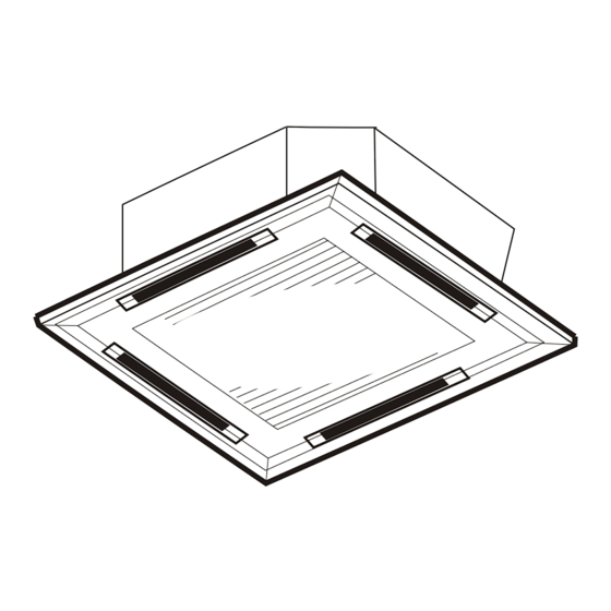
CEILING CASSETTE TYPE
AIR CONDITIONERS
OWNER'S MANUAL
24K/36K/42K/48K
Thank you for choosing our Air Conditioner. Please read this
OWNER'S MANUAL carefully prior to using and keep it for
further reference.
Installation Explanations
Malfunction Codes
(UNIVERSAL SERIES)
18K
1
3
5
6
13
14
15
27
Advertisement
Table of Contents

Subscribe to Our Youtube Channel
Related Manuals for Galanz 18K


Summary of Contents for Galanz 18K
-
Page 1: Table Of Contents
CEILING CASSETTE TYPE AIR CONDITIONERS OWNER'S MANUAL (UNIVERSAL SERIES) 24K/36K/42K/48K Thank you for choosing our Air Conditioner. Please read this OWNER'S MANUAL carefully prior to using and keep it for further reference. Safety Awareness Name of Parts Preparation Before Operation Operation of Air Conditioner Guide to Proper Usage Service and Maintenance... -
Page 2: Safety Awareness
SAFETY AWARENESS Read and understand thoroughly this safety awareness before use. The items indicated here are very important safety precautions, which must be followed. Power resource must be supplied through one specific Do not install the air conditioner near flammable circuit and ensure only one main power switch equipped. - Page 3 SAFETY AWARENESS Read and understand thoroughly this safety awareness before use. The items indicated here are very important safety precautions, which must be followed. Do not insert a finger, a rod or any other objects into the Do not eject any insecticide or flammable spray towards air outlet/inlet grille.
-
Page 4: Name Of Parts
Emergency switch Remote Signal Receiver ALARM lamp RUN lamp DEFROSTING / PREHEATING lamp TIMER lamp For model of 18K A. Air inlet: takes in the room air B. Air outlet C. Deflector: adjust the outlet air direction D. Filter E. Panel F. - Page 5 NAME OF PARTS REMOTE CONTROLLER Signal ejecting window It sends signals to the indoor unit. OPERATION DISPLAY SWING button Press it to change up/down air It displays the current flow direction and the deflector settings. automatically swings up and down. OPERATION SWING MODE button...
-
Page 6: Preparation Before Operation
PREPARATION BEFORE OPERATION Open the back cover, put in Short RESET pieces with batteries and reset the back cover appropriate metal object. as before. NOTICE If the remote controller does not work, short the RESET pieces The signal can be reached within six metres directly in front of indoor unit. -
Page 7: Operation Of Air Conditioner
OPERATION OF AIR CONDITIONER OPERATION WITH REMOTE CONTROLLER Run/Stop Press I/O button once to start operation and press it again to stop operation. Once the air conditioner starts operation, it will sound beep once and the run indicator lamp is illuminated. Temperature Adjustment Every press of button increases the setting temperature by 1 , every... -
Page 8: Cool Mode
OPERATION OF AIR CONDITIONER Room Selected mode Temperature (RT) RT 20 Heating (For cooling only type, dehumidifying mode is selected) RT 24 RT 24 Cooling COOL mode In this mode, press temperature adjustment button to set temperature; press fan speed button to change airflow speed of the indoor unit. Press SWING button to set the airflow angle or adjust the vane swinging up and down. -
Page 9: Timer Operation
OPERATION OF AIR CONDITIONER Timer operation AUTO-ON/OFF timer operation set Press button when the air conditioner is on to initiate the AUTO-OFF TIMER function. Meanwhile, starts to flash on the display. Press button when the air conditioner is off to initiate the AUTO-ON TIMER ¡... - Page 10 OPERATION OF AIR CONDITIONER WIRE CONTROLLER (OPTIONAL) Remote signal receiving spot INDICATION LAMP ON/OFF LCD screen TIME INQUIRY RESET TIME MODE LIGHT SWING SLEEP SPEED WAVE TIME DOWN AUTO-ON COOLING AUTO-OFF AUTO DEHUMIDIFYING HEATING MONTH DATE HOUR MINUTE COMPRESSOR PIN LOCK COOLING LIGHT WAVE DEFROSTING...
- Page 11 OPERATION OF AIR CONDITIONER Installation of Wire Controller When installing back cover of wire controller, fit the lower back cover into the body, hold on and click the upper part into the body, then push them together. When dismantling the back cover, follow the steps below: click click Front Panel...
- Page 12 OPERATION OF AIR CONDITIONER OPERATION WITH WIRE CONTROLLER Run/Stop When ON/OFF button is pressed once, the unit starts and the green lamp illuminates. When ON/OFF button is pressed again, the unit stops and the red lamp illuminates. Temperature Adjustment Every press of UP button increases the setting temperature by 1 , every press of DOWN...
- Page 13 OPERATION OF AIR CONDITIONER Operation mode selection When the unit is at standby state, press MODE button to change its operation modes in the order of: Cooling Dehumidifying Heating Auto Date/Time Setting At normal display page, press TIME button once to set the Date/Time and meanwhile the beeper raises Bi sound once;...
- Page 14 OPERATION OF AIR CONDITIONER Press LIGHT WAVE button once to start light wave function and press it again to stop the function. Once activating light wave function, the lamp will illuminate on the LCD screen of the wire control. Fault and temperature inquiry Every press of ENQUIRY button changes the display pages between normal display page , sensor temperature inquiry page , current fault inquiry page (if the unit...
- Page 15 OPERATION OF AIR CONDITIONER Unit Parameter modification When the unit is off, press SET button for 5 seconds until the beeper raises a Bi sound, and then enter the right password and press SET button again to move into unit parameter modify mode (The word PASS will show up). Note: Contact the local dealer for the password.
-
Page 16: Guide To Proper Usage
GUIDE TO PROPER USAGE Taking care of your unit will allow you to enjoy a more comfortable cooling&heating effect and save more energy. Clean the air purifying filter When cooling, keep away from periodically heat supply objects If the air purifying filter becomes clogged During cooling, draw the curtains with dust/dirt, air flow is restricted and especially for the windows facing the sun... -
Page 17: Service And Maintenance
SERVICE AND MAINTENANCE All the cleaning and maintenance work shall be done by qualified person. Before cleaning or servicing, be sure to stop the operation and turn off the power supply. Cleaning of the air filter and the indoor unit Cleaning of the air filter 1.Remove the air inlet grille and air filter. -
Page 18: Location Of The Indoor Unit
CHOICE OF INSTALL LOCATION INSTALL LOCATION INSTRUCTION Location of the indoor unit The appliance must be installed 2.3m above floor. Mount on the roof or truss solid enough to bear the weight of the indoor unit. A place easy for air circulation around all corners. Keep the air inlet and outlet at a far distance from the blockage. -
Page 19: Installation Of The Indoor Unit
780 A 840 B 880 C 950 D Ceiling Panel For model of 18K: A. Size of outer edge of the unit B. Distance of eyebolt C. Ceiling opening size D. Size of outer edge of the panel E. For... - Page 20 INSTALLATION OF THE INDOOR UNIT DESIGN OF STRUCTURE FOR HANGING Notice: For the sake of safety assurance, the place for hanging must bear enough strength and pressure. The ceiling should keep horizontal. If installed on the declining ceiling, gasket must be inserted between the ceiling and panel. A.
- Page 21 C. Rafter D. Peak girder For 24K, 36K, 42K, 48K For 18K HANG OF THE INDOOR UNIT The eyebolt should be set in this order: M10 nut(1 piece), insulation washer (1 piece, with insulation side downwards), washer (1 piece), nut (2 pieces).
-
Page 22: Installation Of The Outdoor Unit
For models of 24K, 36K, 42K and 48K, please fix the panel to the indoor unit with the hooks on it. For model of 18K, please fix the panel with the screws in it. Notice: if there is no panel to fix on the indoor unit, please use the mounting plate as substitution for dustproof panel. -
Page 23: Installation Of Refrigerant Pipe
PIPELINE INSTALLATION (THE INDOOR UNIT) INSTALLATION OF REFRIGERANT PIPE Installation sequence (1) Keep the original status of closing of gas valve and liquid valve of the outdoor unit. Dismantle the nuts, anti-dust cap and piping screw plugs from the indoor and outdoor pipes respectively, and connect horns of the pipes at the mean time (avoid dust, moisture, and other things getting into the pipes.) Smear a thin layer of seal oil on the matching surface of the horns and the connectors before... -
Page 24: Pipeline Installation
F. Electric cable slot tube 1-1.5m 200mm Downward slope of over 1/100 Where H=215mm, for 18K; H=180mm, for 24K; H=200mm, for 36K&48K. Drain pipe Notice: If the drain pipe (or just part of the pipeline) is arranged higher than the drain port of the indoor unit, the height difference must not exceed 300mm, otherwise the water will overflow when the air conditioner stops. -
Page 25: Electric Installation
ELECTRIC INSTALLATION WIRING OF THE INDOOR UNIT 1. Pull apart the mounting cover panel D at the connecting part of wire. 2. Put the power supply connecting cable, signal connecting cable through Place A, B and the rubber underlay and link the power supply Grounded connecting cable and signal connecting cable correctly. - Page 26 ELECTRIC INSTALLATION 1. Dismantle the maintenance plate on the right side of the unit. 2. Loosen the screws of the wire clamper, then take down the clamper. 3. Connect power cables and signal cables to the connector as wiring diagram on the unit. 4.
-
Page 27: Operation Test
OPERATION TEST CONFIRMATION BEFORE OPERATION TEST After finishing the installation of both indoor and outdoor unit, connection of the pipe and wiring , ensure there is no refrigerant leakage, no loose power supply cord or signal cord and no wrong connection of positive and negative pole. Attention: if there is mistake in power supply cord connecting, the compressor will not run. - Page 28 FAULT INDICATING INSTRUCTIONS FAULT INDICATION ON INDOOR DISPLAY PANEL Display mode Fault Power source fault RUN lamp flashes 1 time, and ALARM lamp illuminates. Communication of wire controller fault RUN lamp flashes 2 times, and ALARM lamp illuminates. Communication of outdoor unit fault RUN lamp flashes 3 times, and ALARM lamp illuminates.
-
Page 29: Fault Indication On Wire Controller
FAULT INDICATING INSTRUCTIONS FAULT INDICATION ON WIRE CONTROLLER Fault Treatment Causes Faults codes Power supply malfunction Fault phase or short of phase. Find the reason then correct the wiring. Communication of wire Wire control is not well connected. Connect the wire control firmly. control malfunction Communication between Indoor unit and outdoor unit are out... - Page 30 Appendix 1 Throttle Device Installation Indoor unit Throttle 1. Take off the end covers of the throttle device, then check if the thread and flare of the joints are in good condition, and then connect A section to the liquid Connecting pipe pipe of the indoor unit, and connect B section to the connecting pipe.
Need help?
Do you have a question about the 18K and is the answer not in the manual?
Questions and answers