Subscribe to Our Youtube Channel
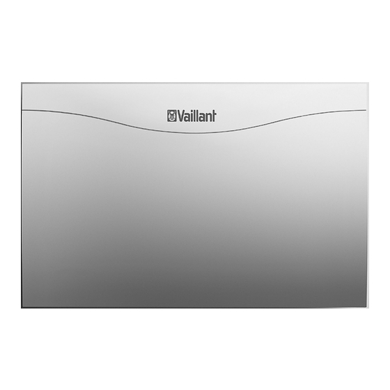
Summary of Contents for Vaillant Mixer module VR 60
- Page 1 For the heating engineer For the heating engineer Installation instructions Installation instructions Mixer module VR 60 Mixer module VR 60 Bus module control system Bus module control system VR 60...
-
Page 2: Table Of Contents
620 or VRC 630 controllers and Vaillant geoTHERM VW../2 heat pumps. Up to a maximum of six mixer modules can be connect- ed. Two additional mixer circuits can be controlled per VR 60 mixer module. Installation instructions Mixer module VR 60 0020020171_02... -
Page 3: Identification Plate
620 or VRC 630 controllers, or the operating section of the Vaillant geoTHERM The mixer module VR 60 must be installed by a qualified VW../2 heat pumps or, if required, via a separate engineer, who is responsible for adhering to the existing VR 80 or VR 90 remote control unit. -
Page 4: Fitting
VR 10 standard sensor • Tilt the casing cover forwards slightly and remove. eBus lead, 3 m long Table 4.1 Scope of delivery of the mixer module VR 60 Accessories VR 90 remote control device For the first eight heating circuits (HK 1 ... HK 8) its own... -
Page 5: Electrical Installation 5
• Wire up the VR 60 mixer module as shown in Fig. 5.1. • Use the supplied eBus connection cable to incorporate the mixer module VR 60 in the communication sys- tem. The eBUS can be branched at any part of the system. -
Page 6: Connecting The Heating Circuit As A Cylinder Charging Circuit (Not With Vaillant Geotherm Vw
PE N L PE N Auf Zu PE N L AF 0 Fig. 5.2 Connection of a heating circuit as a cylinder charging circuit Cylinder charging pump 2 Circulation pump 3 Cylinder sensor Installation instructions Mixer module VR 60 0020020171_02... -
Page 7: Setting The Bus Address
620 or to the individual mixer circuit. To do this set the value 4, VRC 630 controller or the Vaillant geoTHERM VW../2 6, 8, 10, 12 or 14 on the address switch (Fig. 5.3 (3)) de- heat pump. -
Page 8: Warranty And Customer Service
8 Warranty and customer service Warranty and customer service Vaillant warranty We only grant a Vaillant manufacturer's warranty if a suitably qualified engineer has installed the system in accordance with Vaillant instructions. The system owner will be granted a warranty in accordance with the Vaillant terms and conditions.


Need help?
Do you have a question about the Mixer module VR 60 and is the answer not in the manual?
Questions and answers