JUMA PA1000 User Manual
Hide thumbs
Also See for PA1000:
- User manual (15 pages) ,
- User manual (20 pages) ,
- User manual (23 pages)

Subscribe to Our Youtube Channel
Related Manuals for JUMA PA1000


Summary of Contents for JUMA PA1000
-
Page 1: User Manual
JUMA PA1000 Linear Amplifier User Manual JUMA PA1000 User Manual Version 1.27 Page 1 of 15... -
Page 2: Safety Warnings
Precautions! JUMA PA1000 has been designed for SSB and CW operation. It is not designed for 100 % duty cycle key-down operation which is likely to happen in FM, AM, RTTY and digital modes. PA1000 will go to temperature protection during long key-down periods. -
Page 3: Simple User Interface
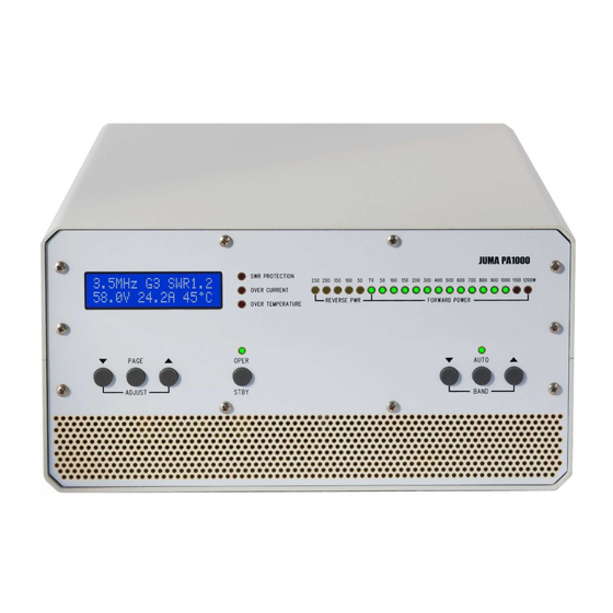
JUMA PA1000 overview Features • Nominal output power 1000 W PEP JUMA PA1000 is a very light weight solid state 1 kW linear amplifier for HF and 6 meter bands. JUMA • All HF bands including WARC bands and 50 MHz PA1000 is using a most modern LDMOS transistor in •... - Page 4 JUMA PA1000 front panel Multi function Protection Reverse power Forward power display indicators LED bar LED bar TX ON LED Display page selection Operate/Standby Band selection and adjustments push button push buttons JUMA PA1000 rear panel Antenna TRCVR RF Band data input,...
- Page 5 1dB. Always start with G1 which is the lowest gain by monitoring the LED bar power indicator. The gain setting is individual for each band. PA1000 will Fan control adjustment. The fan will run with maximum remember the gain settings. Note. EXCITER MAX PWR RPM at the selected final transistor case temperature.
- Page 6 Simply push OPER/STBY button to switch between operate and standby state. LED is ON in operate-state. In start-up the default state is STBY. This can be modified in the service pages so that PA1000 will memorize OPER/STBY state for the next start-up.
- Page 7 3. Connect PTT and band data cable from transceiver. 3. Connect PTT cable from transceiver. See cable You may need one or two cables depending on instructions. In the case of JUMA TRX2 PTT cable is your transceiver. See the cable instructions. In the not needed.
- Page 8 1kΩ. Thus the BCD output signals must be buffered e.g. with a BCD to Decimal decoder IC. If a valid band data is not available PA1000 will output BCD code 1111. If “AllMHz” is manually selected PA1000 will send BCD code 0000.
- Page 9 Both ends 3.5 mm plug. Mono plug can be used in Icom end. A standard 3.5 mm stereo audio cable can NOT be used. PA1000 end of that must be modified. Additionally a PTT cable is needed. Connect it to PTT jack or to the D9 connector.
- Page 10 8 pin DIN male in cable D9 male in cable Note2. Select BCD BAND DATA in PA1000 Note3. In the case of other transceiver refer your transceiver manual for BCD band data ouput and PTT wiring. JUMA PA1000 User Manual Version 1.27...
- Page 11 D9 female in cable Additionally a PTT cable is needed. Use Kenwood REMOTE connector Pin 4 for PTT and Pin 2 for GND. See PA1000 PTT cable in the previous pages. Note also Kenwood menu settings for linear amplifier control.
- Page 12 Cable instructions for transceivers cont. YAESU band voltage (0…5V) YAESU ACC connector JUMA PA1000 BAND DATA/COM2 (FT-817 connector shown) D9 male in cable See your Yaesu manual for correct connector and pin order. Yaesu Band Voltage Table Band Freq Nominal voltage 160 m 1.8 MHz...
- Page 13 Icom band voltage is not supporting 50 MHz and WARC bands but 10 MHz is defined as 0 V. Zero voltage is not a proper level to verify valid band data and thus JUMA PA1000 needs 0.1 V to 1 .0 V for 10 MHz selection.
- Page 14 Service Pages are intended for advanced use, calibration and special settings. If you are not familiar with the service settings do not change anything and exit Service Pages by switching OFF the PA1000. To enter Service Pages keep the PAGE button pressed about 5 seconds until you see text “Service pages selected”.
-
Page 15: Firmware Programming
Firmware programming JUMA PA1000 firmware is easy to update. The latest firmware is available in JUMA PA1000 site. It is a HEX file with a version identification number (e.g. JUMA_PA1000_v102.hex). You can check your current firmware version in your JUMA PA1000 LCD display during start-up.
Need help?
Do you have a question about the PA1000 and is the answer not in the manual?
Questions and answers