
Subscribe to Our Youtube Channel
Related Manuals for JUMA PA100-D


Summary of Contents for JUMA PA100-D
- Page 1 JUMA PA100-D Operation Manual (Firmware Version 4.00a - 11 May 2020) Adrian Ryan - 5B4AIY...
-
Page 3: Table Of Contents
JUMA-TRX2 ........ - Page 4 Juma PA100D Alarm System ........
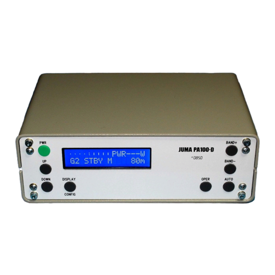
- Page 5 JUMA PA-100D OPERATING MANUAL 5B4AIY Firmware Version: 4.00a The PA-100D is a companion 100W all-band linear amplifier primarily intended for the Juma TRX-2 all-band 10W transceiver, but can also be used with almost any low-power transceiver, such as the Elecraft KX3 Ultra-Portable HF Transceiver, the Elad FDM-DUO, or the Yaesu FT-817/818.
- Page 6 Automatic band request when changing band manually or switching to AUTO/MANUAL. Re-ordered the Auto Band Select to correspond with that in the Juma TRX-2. Automatic setting of the Polling Interval Timer. Set the default polling time interval to 2 seconds from 5 seconds.
-
Page 7: Front Panel Controls
This button now has assigned to it the cancel alarms function, which takes priority. This is to make the alarm system consistent with the Juma TRX-2, whose alarms are also cancelled with its PWR button. In the event an alarm cannot be cancelled, press and hold this button for an emergency shutdown. -
Page 8: Display/Config
Note that each of the 9 amateur bands has its own individual gain setting which can be saved to the EEPROM. If you change a gain setting, a band, or the auto/manual setting, then when you power the amplifier off you will be prompted whether you wish to save the new settings. If either of the buttons is pressed and held, then the button will auto-repeat, and the repeat speed depends upon the parameter being modified. -
Page 9: Auto
To ensure this, if either the Yaesu, KX2/KX3 or Juma TRX-2 mode is active, then a frequency request command will be automatically sent to the connected transceiver whenever a BAND+ or BAND button is pressed or if the mode is switched between MANUAL and AUTO if polling is disabled. -
Page 10: Band
this was assigned to the OPER button, but also assigned to this button at power up is the flash writer. As it can be a little disconcerting to see this prompt, the default reload function has been moved. Release the BAND+ button and the display will prompt you for a selection, either press the BAND+ to reload the default settings, or the PWR button to abort and continue. -
Page 11: Auto Band Detect
The transceiver’s RS-232 port mode should be set to JUMA TRX2, and the port speeds must be the same. The default of 9600 Baud is satisfactory. Note that polling is not required for this mode, and is automatically disabled as the Juma TRX-2 sends a change of band message whenever either a band is changed or the transmit mode is selected if using my firmware. -
Page 12: Serial Port Mode
Note: Both the Remote and Test Modes are only active if the Auto Band Detect is set to either F-Sense or FT-817. If Auto-Band Detect is set to Yaesu CAT, KX3, or Juma TRX-2 modes, then this page is skipped. -
Page 13: Lcd Backlighting
Note: This page is only applicable if the Auto-Band Detect mode is set to Yaesu CAT, KX2/KX3, Juma TRX-2 modes, or the REMOTE serial port mode is selected. In all other modes this page is skipped. LCD Backlighting Default: 300 Limits : 50 –... -
Page 14: Fan Cut-In Temperature
Over-Temperature Limit Default: 70 C/158 F Limits : 50 C – 100 C or 120 F – 212 F Using the UP/DOWN buttons, select a suitable limit. Fan Cut-In Temperature Default: 40 C/104 F Limits : 0 C – 80 C or 32 F – 170 F Using the UP/DOWN buttons, select a suitable temperature for the cooling fan to start. -
Page 15: Graphic Display Scale
If the feature is turned on, then the graphic meter will display the measured parameter in relation to the current trip limits. In other words, when displaying current, the full-scale of the graphic meter is the 24A hardware trip limit, and the display shows the instantaneous value of the current in relation to this limit. -
Page 16: Start-Up Page
+46.0 +47.0 +50.0 Remember that this is a logarithmic display of output power. It is strongly recommended that the graphic display is turned on when using the dBm power scale, and the maximum value set to 100W to alert you to the current output power in relation to the maximum permitted power. Start-Up Page Default: O/P Power This option allows you to choose which measurement system page is displayed on start-up. -
Page 17: Voltage Calibration
calibration pages. The amplifier can only be keyed into the transmit mode if either of these pages are selected. To avoid an accidental over-drive, the input attenuator is set to the minimum gain, which is approximately 10dB. A 5W input signal will drive the amplifier to about 40W – 50W output. The calibration menu pages can be selected by briefly pressing the DISPLAY/CONFIG button. -
Page 18: Current Calibration
Current Calibration Default: 2520 Limits : 1500 – 4000 The current sense is obtained from a precision 0.005Ω current shunt resistor, R7, in series with the main power bus. The voltage developed across this shunt is processed by IC1, a MAX4373 high-side current sense amplifier/convertor and the scaled voltage is measured by the A-D convertor. -
Page 19: Rf Power Calibration (Low Power)
In order to calibrate this measurement, either you will need access to a fairly accurate RF power meter, or you can use an accurate directional coupler and an oscilloscope. In my case I had access to both methods, and was thus able to confirm the relative accuracy of both methods. -
Page 20: Beep Length
Because there are two calibration factors, the overall adjustment tends to be somewhat divergent. If you find that you are arriving at a setting that is near or at the limit of the adjustment factors, then reset the high power calibration factor to around 1150, and the low power calibration factor to about 120, and start again. -
Page 21: Over-Voltage
Power averaging was added to smooth out such transients. The number of samples can be set from 1 (no averaging) to 16. Bear in mind that each sample adds about 4mSec to the time it takes to register the power/SWR. At 16 sample averaging the total recognition time for a high SWR would thus be about 60mSec. -
Page 22: Pre-Limit Voltage (Adjust)
10m band set to an integer number of kilo-hertz, and accurate to ±10Hz, adjust the display to agree with the input. The default band-switch frequency of the Juma TRX-2 of 28.850MHz is ideal. With the calibration factor set to its default value, inject a CW test signal and verify that the correct frequency is displayed. -
Page 23: Splash Screen Display
This setting determines whether the splash screen is displayed during the initialisation phase. If it is set to On, then during the boot phase the following screen is displayed: JUMA-PA100v4.00a OH2NLT OH7SV If it is set to Off, then the amplifier boots up almost immediately. -
Page 24: Annex A
To use this feature, in the User Configuration mode, ensure that Auto Band Detect is set to either the F-Sense or the FT-817 modes. If the YAESU CAT, KX3, or JUMA TRX2 mode is selected, then the test mode is not available. - Page 25 Freq Meter Calibration : 999985 Splash Screen Display : On User Configuration Settings ---------------------------------------- Frequency Sense Mode : F-Sense Serial Link Polling : 5 Seconds RS-232 Port Mode : Test Mode RS-232 Port Speed : 9600 Baud LCD Backlighting : 300 LCD Contrast : 2000 SWR Trip Limit...
- Page 26 809 * 5.000 / 4,096 4,045 / 4,096 = 0.988V This corresponds to a current of 10.193 amps when scaled with the calibration factor of 2520 obtained from the previous dump. The actual calculation is: I = ADC * Calibration Factor / 200,000Amps = 809 * 2520 / 200,000 = 10.193 Amps The second line shows the output of ADC channel 10.
- Page 27 The tolerance is ±100mV. Note that voltages below 0.23V and above 3.1V are invalid. If the input voltage is below 0.23V, then the Out-Of-Band selection is made. Above 3.1V and the unknown selection will be made corresponding to the 28MHz filter. The next line shows the output from ADC channel 12, the reverse power channel used for SWR calculations.
-
Page 28: Temperature Sensor Calibration
Thus, in the temperature sense amplifier A1-B, the potentiometer is used to adjust the offset voltage and calibrate the sensor, and the negative change in DC output voltage is amplified by the x10 DC gain of the inverting amplifier giving approximately +20mV/ C over a range from 0 C –... - Page 29 adjustments. Carefully adjust the calibration potentiometer so that the displayed reading matches as closely as possible that measured with an accurate digital thermometer. Note: The display reading is rounded to the nearest degree in either C or F. Note: When using the serial test suite calibration option no display updates occur. To exit this mode, press any key.
- Page 30 It is beyond the scope of this manual to explain the mapping and contents of the EEPROM. If you are curious, you will need to read the source code, with particular reference to the file: which shows how the data values are mapped. pa100_eeprom.h The first 29 words are used by the user setup contents, and the 30 word is the checksum.
- Page 31 [This page intentionally left blank]...
-
Page 32: Annex B
Annex B Juma PA100D Alarm System The PA100D was provided with an alarm system that would warn the user of over-current, over-temperature, and high SWR conditions. This has now been enhanced with the provision of over-voltage, and under-voltage alarms. The alarm system can be tested using the serial test facility described previously. Enter the letter B and you will be prompted to enter a 1, 2, 3 ,4 , 5, 6 or 7. -
Page 33: Over-Voltage
Over-Voltage Once every cycle of the main control loop, approximately every 4mSec, the battery voltage is measured and compared with the preset threshold. If it exceeds the threshold, and the alarm is enabled, the over-voltage alarm will be raised. This alarm is provided primarily for those using the amplifier in a mobile installation powered from an automobile electrical system. - Page 34 Note that the alarm system can have multiple simultaneous alarms. The design of the firmware is such that the most urgent alarm is cleared first, which will then reveal any lower priority alarms. The next push of PWR button will then clear the most urgent of the remaining alarms, until all the alarms have been cleared.
- Page 35 [This page intentionally left blank]...
-
Page 36: Annex C
Annex C PA-100D & Elecraft KX3 Interconnection Commencing with PA-100D firmware version 1.05h/13/October/2012 the PA-100D incorporates a facility that allows it to be used with the Elecraft KX3 Ultra Portable HF Transceiver. When used with this transceiver the PA-100D will automatically select an amateur band transmit filter set based upon the frequency data it receives from the KX3 via its serial port. -
Page 37: Acc1 To Rs-232 Accessory Cable
must be enabled in order to obtain the transceiver’s current frequency. In this case, for a slightly faster response, a polling rate of 1 seconds is suitable, although even 5 seconds is quite adequate. Note that with Version 4.00a if the KX3 mode is selected then polling is automatically enabled, and set to 2 seconds. - Page 38 KX3 data packets to verify correct operation. For example, to select the 7MHz band, send the ASCII string: FA7000000; and the amplifier should immediately select the 7MHz/40m output filter. By entering the appropriate frequency data in Hz, you should be able to select any of the output filters.
- Page 39 [This page intentionally left blank]...
-
Page 40: Annex D
Annex D Juma PA-100D Remote Control & Status Monitoring This version of the firmware incorporates a feature to allow the amplifier to be controlled remotely via its RS-232 port. If the remote option is used, then automatic band selection must be set to either the Frequency Sense or the FT-817 mode. -
Page 41: Alarm Mapping
Field Value Comment Number O or S Operate or Standby A or M Automatic or Manual mode band selection T or R Transmit or Receive state C or F Centigrade or Fahrenheit temperature scale Band, 1 = 160m – 9 = 10m. 10 = Unknown Band Amplifier gain setting, 1 –... -
Page 42: Remote Timeout
Remote Timeout If polling is disabled, and the amplifier is remotely commanded to the OPERATE state, and no further messages are received, then after 5 seconds the amplifier will revert to the STANDBY state awaiting further commands. Thus, the amplifier should be polled at least every few seconds, and polling every second is recommended. - Page 43 [This page intentionally left blank]...
-
Page 44: Pa-100D Quick Reference Guide
PA-100D QUICK REFERENCE GUIDE BUTTON SHORT PUSH LONG PUSH Power On Power Off Cancel Alarms Select Calibration Mode (From OFF state) Cancel Save Decrement display page (Normal Multiple page decrement (Only in mode) Service or User Configuration mode) Decrement Cal/Config Page (Only in Service or User Configuration mode) Increase Gain... -
Page 45: Pa-100D Calibration Settings
PA-100D CALIBRATION SETTINGS DATA POINT USER DEFAULT Voltmeter 5250 Ammeter 2520 RF Power Factor (High Power) 1200 RF Power Offset (Low Power) Beep Time 50mS Power Averaging Samples Over-Voltage Trip Over-Voltage Trip Limit 14.50 Low Voltage Trip Low Voltage Trip Limit 11.00 Pre-Limit Trip 11.20... -
Page 46: Pa-100D Configuration Settings
PA-100D CONFIGURATION SETTINGS DATA POINT USER DEFAULT Auto Band Detect F-Sense Port Speed 9600 Baud Serial Port Mode Polling Interval 2 Seconds LCD Backlighting LCD Contrast 2000 SWR Trip Limit Temperature Scale Celsius Fan Control Mode Normal Over-temperature Limit 70 C Fan Cut-In Temperature 40 C Band Units...
Need help?
Do you have a question about the PA100-D and is the answer not in the manual?
Questions and answers