LG WD(M)-10130(5)F Service Manual
Lg washing machine service manual
Hide thumbs
Also See for WD(M)-10130(5)F:
- Service manual (37 pages) ,
- Service manual (4 pages) ,
- Service manual (36 pages)
Table of Contents
Advertisement
Advertisement
Table of Contents
Troubleshooting

Related Manuals for LG WD(M)-10130(5)F


Summary of Contents for LG WD(M)-10130(5)F
-
Page 1: Washing Machine
WASHING MACHINE SERVICE MANUAL CAUTION READ THIS MANUAL CAREFULLY TO DIAGNOSE TROUBLE CORRECTLY BEFORE OFFERING SERVICE. MODEL : WD(M)-65130F WD(M)-80130F WD(M)-10130(5)F WD(M)-10131F website : http://www.LGEservice.com e-mail : http://LGEservice.com/techsup.html... -
Page 2: Table Of Contents
1. SPECIFICATION...3 2. FEATURES & TECHNICAL EXPLANATION ... 4 3. PARTS IDENTIFICATION ... 6 4. INSTALLATION ... 7 5. OPERATION ...10 6. WIRING DIAGRAM/PROGRAM CHART ...14 7. TROUBLESHOOTING...15 7-1.BEFORE PERFORMING SERVICE ...15 7-2.TEST MODE ...15 7-3.ERROR DISPLAY ...16 8. ERROR DIAGNOSIS AND CHECK LIST ...17 8-1. -
Page 3: Specification
1. SPECIFICATION ITEM POWER SUPPLY PRODUCT WEIGHT WASHING ELECTRICITY SPIN (800rpm) CONSUMPTION DRAIN MOTOR WASH HEATER REVOLUTION SPEED WASH SPIN OPERATION WATER PRESSURE CONTROL TYPE WASH CAPACITY DIMENSION WASH PROGRAM OPTION DOOR SWITCH TYPE WATER LEVEL SENSING OF THE LAUNDRY AMOUNT FUZZY LOGIC ERROR DIAGNOSIS POWER AUTO OFF... -
Page 4: Features & Technical Explanation
2. FEATURES & TECHNICAL EXPLANATION 2-1.FEATURES Temp. Jumbo drum LG’s jumbo drum can wash about 40% more per load than conventional washing machine. A bigger drum improves the wash performance. Protection against wrinkles With the alternate rotation of the drum, wrinkling in the laundry is minimized. -
Page 5: Water Level Control
2-2.DETERMINE WASHING TIME BY FUZZY LOGIC To get the best washing performance optimal time is determined by sensing of water temperature, selected washing temperature and laundry amount. water temperature selected washing temperature laundry amount SENSING 2-3.WATER LEVEL CONTROL This model adopts a pressure sensor which can sense the water level in the tub. When the water level reaches to the preset level the water supply is stopped, then the washing program proceeds. -
Page 6: Parts Identification
3. PARTS IDENTIFICATION Drawer (For detergent and fabric softener) Door Drain hose Drain pump filter Drain plug ACCESSORIES Power plug If the supply cord is damaged, it must be replaced by the manufacturer or its service agents or a similarly qualified person in order to avoid a hazard. -
Page 7: Installation
4. INSTALLATION Before servicing ask the customer what the trouble is. Check the adjustment (power supply is 220-240V, remove the transit bolts...) Check the troubles referring to the troubleshooting. Decide service steps referring to disassembly instructions. Then, service and repair. After servicing, operate the appliance to see whether it works O K or NOT. -
Page 8: Connect Drain Hose
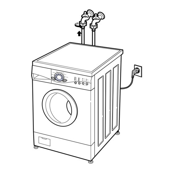
HOW TO CONNECT INLET HOSE Check that the rubber washer is inside of the valve connector. Connect the inlet hose firmly to prevent leak. CONNECT DRAIN HOSE Make sure that the hose is not twisted. The drain hose should be placed under 100cm from the floor. -
Page 9: Test Operation
TEST OPERATION Preparation for washing. Connect the power plug to the outlet. Connect the inlet hose. Check the water heating. Check drain and spin Press the Start/Pause button after selecting Pump button by pressing Program button. Press the power button. In case of cotton program. -
Page 10: Operation
5. OPERATION Wash program selector 8 programs can be set depending on the type of the laundry. By pressing the button [Cotton ➔ Synthetic ➔ Delicate ➔ Wool ➔ Hand Wash ➔ Quick 30 ➔ Rinse+Spin ➔ Pump] can be selected. Power button Press the button to turn on and off. - Page 11 Option Pre Wash If the laundry is heavily soiled, “Pre Wash” course is effective. Pre Wash is available in Cotton and Synthetic Program. Time Save By selecting the Time Save option, the wash time may be reduced, depending on the program selected.
- Page 12 Wash program selector 8 programs can be set depending on the type of the laundry. By pressing the button [Cotton ➔ Synthetic ➔ Delicate ➔ Wool ➔ Hand Wash ➔ Quick 30 ➔ Rinse+Spin ➔ Pump] can be selected. Power button Press the button to turn on and off.
- Page 13 Option Pre Wash If the laundry is heavily soiled, “Pre Wash” course is effective. Pre Wash is available in Cotton and Synthetic Program. Time Save By selecting the Time Save option, the wash time may be reduced, depending on the program selected.
-
Page 14: Wiring Diagram/Program Chart
6. WIRING DIAGRAM Washing Main Washing Staycooling Æ Æ Æ Time 120 MIN 60 (SEC) Cotton Synthetic Delicate Wool Handwash Quick 30 Rinse + Spin Pump Basic Cycle Optional Cycle * Pre-Setting Time : Water Supply - 120 sec. Drain - 60 sec. -
Page 15: Troubleshooting
7. TROUBLESHOOTING 7-1. BEFORE PERFORMING SERVICE ■ Be careful of electric shock or disconnecting the parts while troubleshooting. ■ Voltage of each terminal in 220-240V~ and DC while applying an electric current. 7-2. QC TEST MODE. ① Pressing Temp, and Option button simultaneously. ②... -
Page 16: 7-3.Error Display
7-3.ERROR DISPLAY. If you press the Start/Pause button when an error in displayed, any error except S/W ERROR will disappear and the machine will change into pause status. In case of SENSOR PRESSURE S/W ERROR error is not resolved within 20 sec. In the case of other errors, if the error is not resolved within 4 min. power will be turned off automatically and the error code will be blinked. -
Page 17: Error Diagnosis And Check List
8. ERROR DIAGNOSIS AND CHECK LIST 8-1.DIAGNOSIS AND ANSWER FOR ABNORMAL OPERATION SYMPTOM NO POWER Water inlet trouble Rinse+ Crease Care GUIDE FOR SERVICE CALL Is the power plug connected firmly to 220-240V~ outlet? Power failure? or Breaker opened? Is the outlet controlled by a switch. Visit to check Rinse+ displayed? -
Page 18: Door Open Error
SYMPTOM DOOR OPEN ERROR Refer to 7-3 ERROR DISPLAY Drain Trouble Pre Wash Time Save GUIDE FOR SERVICE CALL Did you press the Start/Pause button when the door is open? Visit to check Check if the door switch is O.K Pre Wash displayed? Time Save... - Page 19 SYMPTOM Suds overflow from the appliance. (In this condition, wash and spin do not operate normally) No effect of softener 95˚C Pre Wash Rinse+ Crease Care Time Save Cold Pre Wash Rinse+ 95˚C Crease Care Time Save Cold GUIDE FOR SERVICE CALL Is low-sudsing detergent for the durm washing machine used? Is the proper amount of detergent used...
-
Page 20: Fault Diagnosis And Troubleshooting
8-2.FAULT DIAGNOSIS AND TROUBLESHOOTING CAUTION 1. Be careful of electric shock or disconnecting the parts while troubleshooting. 2. First of all, check the connection of each part terminal with wiring diagram. 3. If you replace the PWB assembly (Main), put in the connectors correctly. When measuring the voltage of the outlet, is the voltage AC 220-240V? When measuring the voltage of White(3pin) -
Page 21: No Water Supply
Is the water supply shut-off? Is the tap opened? Is the inlet valve filter clogged with impurity? option (HOT) Is resistance of the inlet valve connector between the 2 to 8 Check the voltage between each terminals of inlet Valve is 220 - 240V~. (Refer to 7-2 TEST MODE) Is water supplied? option (HOT) -
Page 22: Softener Does Not Flow In
SOFTENER DOES NOT FLOW IN option (HOT) Is water supplied? Are receptacles correctly connected to the terminals of inlet valve? Wiring diagram Is softener put in the correct compartment of drawer? Is the softener cap clogged? Is the pulley bolt loosened? Is the belt worn? Is there friction noise from the motor? ABNORMAL SOUND... -
Page 23: Heating Without Water
Are there any problem at air chamber, the hose or pressure sensor? Replace the PWB assembly. PWB ASSEMBLY Is the drain hose twisted or frozen? Is the impeller of the drain pump clogged? Is the connector disconnected, disassembled? Is the coil of drain pump cut-off? (resistance of coil is 90~160 ) When checking voltage between connectors as the figure? - Page 24 WASH HEATER TROUBLE When checking the voltage between two receptacles of the PWB assembly during washing. Is the voltage AC 220-240V? AC 220-240V After power off, is the resistance between yellow wire and red wire of connector 10 to 30 ? After power off, is the resistance of heater 10 to 30 ? HEATING CONTINUOUSLY ABOVE...
-
Page 25: Spin Trouble
Check the sensor (Pressure) or hose (Sensor). If the problem is on the sensor or the hose, replace the sensor or the hose. Press Power button with both Temp. and Option buttons pressed after power off. Press Start/Pause Option Temp. button 2 times. -
Page 26: Disassembly Instructions
9. DISASSEMBLY INSTRUCTIONS Be sure to unplug the machine out of the outlet before disassembling and repairing the parts. CONTROL PANEL PLATE ASSEMBLY (TOP) PANEL ASSEMBLY (CONTROL) PWB ASSEMBLY Unscrew 2 screws on the back of the top plate. Pull the top plate backward and upward as shown. Disconnect the PWB Assembly connector from Main lead wire Assembly. -
Page 27: Dispenser Assembly
DISPENSER ASSEMBLY Disassemble the top plate assembly. Pull out the drawer to arrow direction. Unscrew 2 screws. DRAWER The hose clamps and the hose are disassembled. Option The ventilation bellows and the water inlet bellows are disassembled on the tub. DISPENSOR ASSEMBLY... -
Page 28: Inlet Valve
INLET VALVE LOWER COVER DOOR Disconnect the wiring receptacle. Unscrew 2 screws from the back. When reconnecting the connector VALVE #1 (MAIN) Whited/Black-Black VALVE #2 (PRE) Black - Gray VALVE #3 (HOT) Blue/White - Black Open the lower cover plate by using coin and pull out the lower cover in the arrow direction after a screw is unscrewed. -
Page 29: Gasket Assembly
GASKET ASSEMBLY Take apart the cabinet gasket clamp. Unscrew 2 screws from the cabinet cover. Open the lower cover cap and unscrew 1 screw inside. Take apart the lower cover. Unscrew all the screws on the upper and lower sides of the cabinet cover. -
Page 30: Clean The Drain Pump Filter
PULLEY, MOTOR, DAMPER Damper Hinge, Damper Clean the drain pump filter Open the lower cover cap ( ) by using a finger Turn the drain plug ( ) to pull out the hose. Remove the back cover. Take off the belt turning the pulley. Unscrew the bolt to pull out the pulley. -
Page 31: Thermistor
PUMP Pump Outlet Hose Screw (Remaining Hose) HEATER THERMISTOR Remove pump outlet hose. Remove tub pump bellows. Remove cap (Remaining Hose.) Disconnect the wiring. Unscrew 2 screws. Remove the pump. Tub Pump Bellows Loosen the M6 heater nut to pull out the heater. CAUTION When mounting the heater, be sure to insert the heater into the heater clip on the bottom of the tub. -
Page 32: Switch Assembly/Door Lock
SWITCH ASSEMBLY, DOOR LOCK WHEN FOREIGN MATERIAL IS STUCK BETWEEN DRUM AND TUB Take apart the cabinet cover clamp and release the gasket. Unscrew 2 screws holding the door lock. Disconnect the door lock from the wiring connector. Remove the heater. Remove the foreign material (wire, coin and others) by inserting a long bar through the hole. -
Page 33: Exploded View
10. EXPLODED VIEW 10-1.THE EXPLODED VIEW OF CABINET ASSEMBLY A480 A485... -
Page 34: The Exploded View Of Control Panel & Dispenser Assembly
10-2 THE EXPLODED VIEW OF CONTROL PANEL & DISPENSER ASSEMBLY F430 A450... -
Page 35: The Exploded View Of Drum & Tub Assembly
10-3 THE EXPLODED VIEW OF DRUM & TUB ASSEMBLY... -
Page 36: Appendix (Replacement Parts List)
Mar. 2002 PRINTED IN KOREA P/No.:3828ER3013A...
Need help?
Do you have a question about the WD(M)-10130(5)F and is the answer not in the manual?
Questions and answers
Какие подшипники стоят на барабане?