Table of Contents
Advertisement
Advertisement
Table of Contents

Related Manuals for Corvalent Q77AX


Summary of Contents for Corvalent Q77AX
- Page 1 Q77AX USER MANUAL Part Number: Q77AX...
-
Page 2: Table Of Contents
Table of Contents REVISION HISTORY ......................... 4 PREFACE SAFETY PRECAUTIONS WARNING!..................6 Static Electricity Warning! ........................6 FCC Notice ............................6 CE Notice ............................. 6 Conventions Used in this Manual ......................6 CHAPTER 1 TECHNICAL SPECIFICATIONS ..............7 Embedded Processor (1155 LGA package) ..................7 Non-Embedded Processors ......................... - Page 3 System Memory Map.......................... 65 Interrupt Map ............................66 Graphics Features ..........................67 APPENDIX B FLASH BIOS PROGRAMMING ..............69 How to Reflash the BIOS ........................69 APPENDIX C EFI BIOS AND POST CODES ...............70 Checkpoint Ranges ..........................70 Standard Checkpoints ........................71 APPENDIX D SATA INTERFACES ..................79 RAID 0 ..............................
-
Page 4: Revision History
Revision History Revision Revision History Date First Release 01/31/13 Notice The company reserves the right to revise this publication or to change its contents without notice. Information contained herein is for reference only and does not constitute a commitment on the part of the manufacturer or any subsequent vendor. -
Page 5: Preface
With proper installation and maintenance, your board will provide years of high performance and trouble free operation. This manual provides a detailed explanation into the installation and use of the Q77AX industrial embedded motherboard. It is written for the novice PC user installer. -
Page 6: Safety Precautions Warning
Safety Precautions Warning! Static Electricity Warning! The Q77AX motherboard has been designed as rugged as possible but can still be damaged if jarred sharply or struck. Handle the motherboard with care. It contains delicate electronic circuits that can be damaged or weakened by static electricity. Before removing the board from its protective packaging, it is strongly recommended that you use a grounding wrist strap. -
Page 7: Chapter 1 Technical Specifications
Chapter 1 Technical Specifications The Q77AX is a long-life industrial motherboard with multi-core processor technology and PCI Express 2.0 and 3.0 support (depending on the processor). Powered by the Intel® Q77 Express chipset (Panther Point), the Q77AX motherboard was designed specifically for embedded applications such as Medical, Security, Imaging, Industrial Automation, and Manufacturing that require a smaller, compact footprint. -
Page 8: Peripheral Chips
Peripheral Chips Fintek F71869AD SIO chip) Two full handshake COM ports PS/2 keyboard and mouse header Hardware voltage monitor /CPU temp. monitor Watchdog timer PWM fan control outputs / tachometer inputs CPU thermal diode monitoring Fintek F81216AD Four full handshake COM ports System Memory Four DIMM sockets, supporting up to 32GB of unbuffered non-ECC DDR3 memory. -
Page 9: Miscellaneous
Intel 82574L Gigabit Ethernet PCI-E Gigabit Ethernet controller 10/100/1000 Mbps full and half duplex operation Intel 82579LM Gigabit Ethernet PCH Integrated Gigabit Ethernet controller 10/100/1000 Mbps full and half duplex operation Miscellaneous CMOS/Battery RTC integrated in PCH CR2032 lithium battery or equivalent Watchdog Timer Reset: 1~65535 sec./min and 1 min./step Expansion... -
Page 10: Chapter 2 Hardware Configuration
DRAM and jumper settings. Handling Precautions The Q77AX has been designed to be as rugged as possible but it can be damaged if dropped, jarred sharply or struck. Damage may also occur by using excessive force in performing certain installation procedures such as forcing the system board into the chassis or placing too much torque on a mounting screw. -
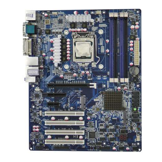
Page 11: Connector Locations
Connector Locations ATX12V (LGA1155) DP1/USB4 DDR3 DIMM COM1I/COM2 DVI/VGA ATXPWR UL2/USB UL1/USB MINIPCIE AUDIO1 SATAIII SATA(1-2) SATAII SATA(3-4) SATAII SATA(5-6) PCI1 PCI2 MSATA PCI3 PCI4... -
Page 12: Header Locations
Header Locations CPUFAN KBMS SYSFAN1 USB1 SM_BUS NIC2_LED COM5 COM3 SPEAK NIC1_LED PWR_LED FPANEL COM4 JP14 SPDIF SYSFAN2 FP_AUDIO USB3 PARALLEL USB2 TX-RXCOM COM6 GPIO... -
Page 13: Jumper Locations
Jumper Locations JBAT JP16 JP15 JP12... - Page 14 Jumpers, Connectors and Headers Quick Reference Table Jumpers Name Description JBAT CMOS Reset 3x1 header, pitch 2.54mm COM1 RI Function Selection 3x2 header, pitch 2.54mm Mini-PCI-E Standby Voltage Selection 3x1 header, pitch 2.54mm COM3 RI Function Selection 3x1 header, pitch 2.54mm COM5 RI Function Selection 3x1 header, pitch 2.54mm COM4 RI Function Selection...
- Page 15 Connector Name Description Type AUDIO1 Line-out/Line-in/Microphone 3 phone Jack ATXPWR ATX Power Connector 12x2 connector ATX12V ATX 12V Connector 2x2 connector COM1 Serial Port connector DB-9 COM2 Serial Port connector DB-9 Processor Socket 1155 pin LGA socket DIMM DDR3 DIMM memory sockets 240 pin DVI-D Displayport...
-
Page 16: Setting The Jumpers
Jumpers or headers are small pins attached to the system board. Covering two pins with a shunt closes the connection between them. The Q77AX examines these jumpers to determine specific configuration information. There are two different categories of jumpers on the Q67IX. -
Page 17: Jumpers
Jumpers Use the diagram below and the tables on the following pages to locate and set the on-board configuration jumpers. JBAT: Clear CMOS 1-2: CMOS Normal 2-3: CMOS Reset JP1: COM1 RI Function Selection 1-2 closed: RS232 3-4 closed : +12V 5-6 closed : +5V... - Page 18 JP2: Mini-PCI-E Standby Voltage Selection 1-2: 3.3V 2-3: 3.3VSTBY JP4: COM3 RI Function Selection 1-2 closed: RS232 3-4 closed : +12V 5-6 closed : +5V...
- Page 19 JP5: COM5 RI Function Selection 1-2 closed: RS232 3-4 closed : +12V 5-6 closed : +5V JP8: COM4 RI Function Selection 1-2 closed: RS232 3-4 closed : +12V 5-6 closed : +5V...
- Page 20 JP9: COM6 RI Function Selection 1-2 closed: RS232 3-4 closed : +12V 5-6 closed : +5V JP12: COM3 Header RS232/422/485 Selection 1-2: RS232 3-4: RS485 5-6: RS422...
- Page 21 JP15: Internal POST display (left) JP16: Internal POST display (right) Removing JP15 and JP16 enables support for a remote POST display connected to JP14...
-
Page 22: Headers
Headers Use the diagram below and the tables on the following pages to locate the headers. COM3/COM4/COM5/COM6: Serial Ports ASSIGNMENT ASSIGNMENT CASE_OPEN: Chassis Intrusion Header Connect your chassis intrusion switch (normally closed) to this 2 pin header. In case the chassis is opened (closing the switch), a message will be displayed onscreen to inform you of this when the computer is restarted. - Page 23 CPUFAN: Processor Fan header (PWM) ASSIGNMENT Tachometer FP_AUDIO: Front Panel AUDIO header ASSIGNMENT ASSIGNMENT MIC-L AGND MIC-R Presence LINE-OUT-R Front Sense LINE-OUT-L...
- Page 24 GPIO_CON: GPIO header ASSIGNMENT ASSIGNMENT GPIO_30 GPIO_31 GPIO_32 GPIO_33 GPIO_34 GPIO_35 GPIO_36 GPIO_37 HDMI_SPDIF: SPDIF Out header ASSIGNMENT SPDIF...
- Page 25 FPANEL: Front Panel header ASSIGNMENT ASSIGNMENT Power SW (GND) Reset SW Power SW Reset SW (GND) Power LED (-) HDD LED (-) Power LED (+) HDD LED (+) KBMS: PS/2 Keyboard/Mouse header ASSIGNMENT KBCLK KBDATA MSDATA MSCLK...
- Page 26 NIC1_LED: LAN1 LED header ASSIGNMENT LED+ LED- NIC2_LED: LAN2 LED header ASSIGNMENT LED+ LED-...
- Page 27 PARALLEL: Parallel Port header ASSIGNMENT ASSIGNMENT STB# AFD# ERR# INIT# SLIN# ACK# BUSY SLCT...
- Page 28 PWR_LED: Legacy Power LED header ASSIGNMENT SM_BUS: SMBUS header ASSIGNMENT SM Data SM Clock...
- Page 29 SPEAK: Legacy Speaker header ASSIGNMENT SPEAK SYSFAN1: System fan header ASSIGNMENT Tachometer...
- Page 30 SYSFAN2: System fan header ASSIGNMENT Tachometer TPM: Trusted Platform Module header ASSIGNMENT ASSIGNMENT LFRAME RESET VCC5V LAD3 LAD2 VCC3.3 LAD1 LAD0 GPIO GPIO 3.3VSTBY SERIRQ GPIO GPIO...
- Page 31 TX-RXCOM2: RS-422/485 ASSIGNMENT ASSIGNMENT TXDN RXDN TXDP RXDP USB1: USB3.0 header ASSIGNMENT ASSIGNMENT VBUS SSRX1- VBUS SSRX1+ SSRX2- SSRX2+ SSTX1- GND0 SSTX1+ SSTX2- SSTX2+...
- Page 32 USB2: USB2.0 header ASSIGNMENT ASSIGNMENT USB3: USB2.0 header ASSIGNMENT ASSIGNMENT...
-
Page 33: Connectors
Connectors ATXPWR: ATX Power Connector Connect the power supply to the 24 pin ATX Power Connector ATX12V: ATX 12V Connector CPU: Processor Socket... - Page 34 DIMMs Mini-PCIe: Half size mini-PCIe Connector...
- Page 35 MSATA: Full/Half size MSATA Connector PCI1: PCI 32bit PCI2: PCI 32bit...
- Page 36 PCI3: PCI 32bit PCI4: PCI 32bit PE1: PCI Express x16...
- Page 37 PE2: PCI Express x4 PE3: PCI Express x1 SATA1 and 2: Shrouded SATAIII (6Gb/s) connectors...
- Page 38 SATA3, 4, 5 and 6: Shrouded SATAII (3Gb/s) connectors...
-
Page 39: Installing Memory
Firmly press the modules into the socket until it snaps into place. Always start installing memories on the blue sockets first, black sockets second. Adding memory modules to the Q77AX is only allowed for specific configurations. Contact your Sales representative to confirm your configuration. Unreliable and incorrect operation... -
Page 40: Installing Cpu
Installing CPU To properly install the processor, make sure to carefully follow these instructions: Push the lever down, unclip and lift it. Open the load plate Remove the plastic cover. Carefully align processor with notches on the socket Close the load plate, close and latch the lever... -
Page 41: Installing Heat Sink/Fan
Installing HEAT SINK/FAN The processors supported by the Q77AX require the use of a heat sink/fan. Make sure to install it properly, to avoid overheating. Recommended heat sink/fans require a screwdriver to attach it to a metal bracket installed underneath (solder side) of the board. -
Page 42: Back Panel Connections
Back Panel Connections A – USB3.0 connectors Standard dual USB3.0 connector. B – COM1 Connector (DB9M) C – DVI-D D – NIC2 and USB Stacked RJ45 and USB. E – NIC1 and USB Stacked RJ45 and USB. F – AUDIO Stack Line-in, Speaker and Microphone Audio stack G –... -
Page 43: Chapter 3 Amibios Setup
Chapter 3 AMIBIOS Setup The Q77AX motherboard features the American Megatrends EFI BIOS. The system configuration parameters are set via the BIOS setup. Since the BIOS Setup resides in the ROM BIOS, it is available each time the computer is turned on. - Page 44 The CMOS BIOS setup/utility uses a key-based navigation system called hot keys. Most of the setup utility hot keys can be used at any time during the setup navigation process. These keys include <F1>, <F10>, <Enter>, <ESC>, <Arrow> keys, and so on. Note: There is a hot key legend located in the right frame on most setup screens.
- Page 45 HOT KEY DESCRIPTION The <F1> key allows you to display the General Help screen. Press the <F1> key to open the General Help screen. The <F2> key reloads the previous value entered. The <F3> key loads Optimal Defaults The <F4> Saves the selected settings The <Esc>...
-
Page 46: Main Setup
Main Setup When you first enter the CMOS Setup Utility, you will enter the Main setup screen. You can always return to the Main setup screen by selecting the Main tab. This screen shows some basic system information, like the BIOS Version and Identification, the processor parameters and also the date and time settings. -
Page 47: Advanced Bios Setup
Advanced BIOS Setup BIOS SETUP UTILITY Main Advanced Chipset Boot Security Save & Exit Legacy OpROM Support Launch External PXE OpROM [Disabled] Launch LAN1 PXE OpROM [Disabled] Launch LAN2 PXE OpROM [Disabled] Launch Storage OpROM [Enabled] ERP Function [Disabled] ► PCI Subsystem Settings ►... -
Page 48: Pci Subsystem Settings
Legacy OpROM Support Launch External PXE OpROM Enable or Disable Boot option for Legacy Add-on Network Devices Launch LAN1 PXE OpROM Enable or Disable Boot option for LAN1 PXE Launch LAN2 PXE OpROM Enable or Disable Boot option for LAN2 PXE Launch Storage OpROM Enable or Disable Boot option for Legacy Mass Storage Devices ERP Function Energy Related Products function Enable or Disable ►... - Page 49 ►PCI Express Link Settings Relaxed Ordering Enable or Disable Extended Tag Enable or Disable No Snoop Enable or Disable Maximum Payload Auto or select Maximum Read Request Auto or select PCI Express Link Register Settings Disable, Auto or Force LOs ASPM Support Warning: Enabling ASPM may cause some PCI-E devices to fail...
-
Page 50: Trusted Computing
► ACPI Settings Screen ACPI Sleep State S1 (CPU Stop Clock) or S3 (Suspend to RAM) Enabled or Disabled S3 Video Repost ► Wakeup function Settings Enabled or Disabled Wake System with Fixed Time PS2 KB/MS Wakeup Enabled or Disabled PCI PME Wakeup Enabled or Disabled USB S3/S5 Wakeup... -
Page 51: Sata Configuration
L1 Data Cache 32 KB x 4 L1 Code Cache 32 KB x 4 L2 Cache 256 KB x 4 L3 Cache 8192 KB Hyper-threading Enable or Disable Active Processor Cores All, 1, 2 or 3 Limit CPUID Maximum Enable or Disable Execute Disable Bit Enable or Disable Intel®... -
Page 52: Amt Configuration
► AMT Configuration Intel AMT Enabled or Disabled BIOS Hotkey Pressed Enabled or Disabled MEBx Selection Screen Enabled or Disabled Hide Un-Configure ME Enabled or Disabled Confirmation Enabled or Disabled MEBx Debug Message Output Un-Configure ME Enabled or Disabled Amt Wait Timer Disable ME Enabled or Disabled Enabled or Disabled... -
Page 53: Smart Settings
Mass Storage Devices: Sandisk Cruzer 8.02 Auto or Emulation Mode ► SMART Settings SMART Self Test Enabled or Disabled ► Super IO Configuration Super IO Configuration ► COM1 Port Configuration Disabled or Enabled Serial Port Device Settings IO=3F8h; IRQ=4; Auto or Allows to change settings Change Settings ►... -
Page 54: Second Super Io Configuration
► Second Super IO Configuration Second Super IO Configuration ► COM3 Port Configuration Serial Port Disabled or Enabled Device Settings IO=4E0h; IRQ=10; Change Settings Auto or Allows to change settings Serial Port Mode Select RS232 or RS422/485 ► COM4 Port Configuration Serial Port Disabled or Enabled Device Settings... -
Page 55: Watchdog Configuration
► Watchdog Configuration Watchdog Configuration Enabled or Disabled Watchdog Timer Control Watchdog Timer Val Set from 4 to 255 Seconds or Minutes Watchdog Timer Unit ► Shutdown Temperature Configuration Shutdown Temperature Disabled 60 C/140 F 65 C/149 F 70 C/158 F 75 C/167 F ►... - Page 56 SYSFAN1 Idle Temp SYSFAN1 Stop Temp SYSTEM2 3/4 Pin Fan Select 3 Pin or 4 Pin SYSFAN2 Smart Mode Enabled or Disabled SYSFAN2 Full Speed Temp SYSFAN2 Idle Temp SYSFAN2 Stop Temp...
-
Page 57: Chipset Setup
Chipset Setup BIOS SETUP UTILITY Main Advanced Chipset Boot Security Save & Exit North Bridge Parameters .PCH-IO Configuration ► System Agent (SA) Configuration ► ← ← ← ← : Select Screen ↑ ↑ ↑ ↑ ↓ ↓ ↓ ↓ : Select Item Enter: Select +/-: Change Opt. - Page 58 ► PCH-IO Configuration ► USB Devices Configuration XHCI Pre-Boot Driver Disabled or Enabled xHCI Mode Smart Auto, Auto, Enabled or Disabled HS Port #1 Switchable Disabled or Enabled HS Port #2 Switchable Disabled or Enabled HS Port #3 Switchable Disabled or Enabled HS Port #4 Switchable Disabled or Enabled Disabled or Enabled...
- Page 59 ► PE3 Slot Configuration PE2 Slot Disabled or Enabled ASPM Support Disabled, L0s, L1, LosL1 or Auto Disabled or Enabled Disabled or Enabled NFER Disabled or Enabled Disabled or Enabled Disabled or Enabled SEFE Disabled or Enabled SENFE Disabled or Enabled SECE Disabled or Enabled PME SCI...
-
Page 60: Graphics Configuration
Extra Bus Reserved Reserved Memory Reserved I/O Azalia HD Audio Disabled, Enabled or Auto Azalia internal HDMI Codec Disabled or Enabled Onboard LAN1 Controller Disabled or Enabled Wake on LAN1 from S5 Disabled or Enabled Onboard LAN2 Device Disabled or Enabled DeepSx Power Policies Disabled, Enabled in S5 or Enabled in S4-S5 High Precision Event timer Configuration... -
Page 61: Nb Pcie Configuration
► NB PCIe Configuration PEG0 Auto, Gen1, Gen2 or Gen3 PEG0 – Gen X Disabled, Auto, ASPM L0s, ASPM L1 or ASPM L0sL1 PEG0 ASPM Disabled, Enabled or Auto Enable PEG De-emphasis Control -6dB or -3.5dB ► Memory Configuration Memory Information Memory Frequency 1333MHz Total Memory... -
Page 62: Boot Setup
Boot Setup BIOS SETUP UTILITY Main Advanced Chipset Boot Security Save & Exit Boot Configuration Setup Prompt Timeout Bootup NumLock Sate [Off] Quiet Boot [Disabled] Fast Boot [Enabled] Skip VGA [Disabled] Skip USB [Disabled] Skip PS2 [Disabled] CSM16 Module Version 07.68 GateA20 Active [Upon Request]... -
Page 63: Security Setup
Boot Configuration Setup Prompt Timeout Select number of seconds for Setup from 1 to 65535 Bootup NumLock State NUM-LOCK on boot: On or Off Enable or Disable Quiet Boot Fast Boot Enable or Disable Skip VGA Enable or Disable Skip USB Enable or Disable Skip PS2 Enable or Disable... -
Page 64: Save & Exit Menu
Save & Exit Menu BIOS SETUP UTILITY Main Advanced Chipset Boot Security Save & Exit Save Changes and Reset Discard Changes and Reset Restore Defaults Save as User Defaults Restore as User Defaults Boot Override ← ← ← ← : Sel ect Sc ree n P0: PLEXTOR DVDR PX-880SA ↑... -
Page 65: Appendix Atechnical Summary
512K CONVENTIONAL MEMORY The Q77AX can address up to 32GB of RAM. Typically the address space that is allocated for PCI add-in cards, PCI Express configuration space, BIOS, and chipset overhead resides above the top of RAM. On a system that has 32GB of memory installed, it is not possible to use all of the installed memory due to system address space being allocated for other system critical functions. -
Page 66: Interrupt Map
Interrupt Map PRIORITY STANDARD FUNCTION System Timer Keyboard Controller Programmable Interrupt Communications Port (COM2) Communications Port (COM1) Floppy Disk Controller System CMOS/Real Time Clock ACPI Mode when enabled Available Available PS/2 Compatible Mouse Port Numeric Data Processor Prim. SATA Channel Sec. -
Page 67: Graphics Features
Graphics Features Intel® HD Graphics Subsystem The graphics engine built into the 2 generation processors is able to achieve high performance at lower power consumption. It supports the next generation Intel clear video Technology HD, that is a collection of video playback and enhancement features that improve the end user’s viewing experience. - Page 68 Analog CRT • Analog Monitor Support up to 2048x1536 @75Hz (QXGA) Displayport • The Displayport can support a maximum screen resolution of 2560 x 1600 (actual resolution depending on the monitor used) and high-quality audio playback.
-
Page 69: Appendix Bflash Bios Programming
Appendix B Flash BIOS Programming The Q77AX uses a standard SPI FLASH BIOS. When updating your BIOS, make sure you have the correct batch file that contain all the necessary files for the upgrade. You will also need a bootable device, like a floppy, USB or hard-drive, loaded with DOS. -
Page 70: Appendix Cefi Bios And Post Codes
Appendix C EFI BIOS and POST Codes The status code, or POST code, is used to indicate progress during the boot phase. A subset of these status codes, also known as checkpoints, indicates common phases of the boot process. Checkpoints are very useful to determine the cause of a failure or problem during the pre-boot process. -
Page 71: Standard Checkpoints
Standard Checkpoints SEC Phase Status Code Description 0x00 Not Used Progress Codes 0x01 Power on. Reset type detection (soft/hard) 0x02 AP initialization before microcode loading 0x03 Northbridge initialization before microcode loading 0x04 Southbridge initialization before microcode loading 0x05 OEM initialization before microcode loading 0x06 Microcode loading 0x07... - Page 72 Status Code Description Progress Codes 0x16 Pre-memory Northbridge initialization (Northbridge module specific) 0x17 Pre-memory Northbridge initialization (Northbridge module specific) 0x18 Pre-memory Northbridge initialization (Northbridge module specific) 0x19 Pre-memory Southbridge initialization is started 0x1A Pre-memory Southbridge initialization (Southbridge module specific) 0x1B Pre-memory Southbridge initialization (Southbridge module specific) 0x1C Pre-memory Southbridge initialization (Southbridge module specific)
- Page 73 PEI Error Codes 0x50 Memory initialization error. Invalid memory type or incompatible memory speed 0x51 Memory initialization error. SPD reading has failed 0x52 Memory initialization error. Invalid memory size or memory modules don’t match 0x53 Memory initialization error. No usable memory detected 0x54 Unspecified memory initialization error 0x55...
- Page 74 Recovery Error Codes 0xF8 Recovery PPI is not available 0xF9 Recovery capsule is not found 0xFA Invalid recovery capsule 0xFB – 0xFF Reserved for future AMI error codes PEI Beep Codes # of Beeps Description Memory not installed Memory was installed twice (InstallPeiMemory routine in PEI called twice Recovery started DXEIPL was not found DXE Core Firmware Volume was not found...
- Page 75 Status Code Description 0x6D Northbridge DXE initialization (NB module specific) 0x6E Northbridge DXE initialization (NB module specific) 0x6F Northbridge DXE initialization (NB module specific) 0x70 Southbridge DXE initialization is started 0x71 Southbridge DXE SMM initialization is started 0x72 Southbridge devices initialization 0x73 Southbridge DXE initialization (SB module specific) 0x74...
- Page 76 Status Code Description 0xA3 IDE enable 0xA4 SCSI initialization is started 0xA5 SCSI reset 0xA6 SCSI detect 0xA7 SCSI enable 0xA8 Setup verifying Password 0xA9 Start of setup 0xAA Reserved for ASL 0xAB Setup input wait 0xAC Reserved for ASL 0xAD Ready to boot event 0xAE...
- Page 77 DXE Error Codes 0xD9 Error loading Boot option 0xDA Boot option is failed 0xDB Flash update is failed 0xDC Reset protocol is not available DXE Beep Codes # of Beeps Description Invalid password Some of the Architectural protocols are not available No console output devices are found No console input devices are found Flash update is failed...
- Page 78 OEM-Reserved Checkpoint Ranges Status Code Description 0x05 OEM SEC initialization before microcode loading 0x0A OEM SEC initialization after microcode loading 0x1D – 0x2A OEM pre-memory initialization codes 0x3F – 0x4E OEM PEI post memory initialization codes 0x80 – 0x8F OEM DXE initialization codes 0xC0 –...
-
Page 79: Appendix Dsata Interfaces
Appendix D SATA Interfaces The Q77AX provides a total of six SATA connectors. SATA ports 1 through 6 support the Intel Rapid Storage Technology (Intel® RST) and allow for the following RAID modes: RAID 0 RAID 0 - Striped Disk Array without Fault Tolerance: Provides data striping (spreading out blocks of each file across multiple disk drives) but no redundancy. -
Page 80: Raid 10
RAID 10 RAID 10 is a hybrid of RAID 0 and RAID 1. This configuration is known as a striped mirrored array. See the illustration below for a graphical representation of RAID 10. RAID 5 RAID 5 – (block-level striping with distributed parity) distributes parity along with the data and requires all drives but one to be present to operate;... -
Page 81: Intel® Rapid Recovery Technology
Intel® Rapid Recovery Technology SATA ports 1 through 6 also support Intel ® Rapid Recover Technology. It uses RAID 1 to copy data from a master drive to a secondary, or recovery drive. This process can be configured to be continuous or on request. -
Page 82: Loading The Intel Matrix Storage Technology Raid Driver
Below is an example of the RAID Configuration Screen [MAIN MENU] 1. Create RAID Volume 2. Reset Disks to Non-RAID 3. Delete RAID Volume 4. Recovery Volume Options 5. Exit [DISK/VOLUME INFORMATION] RAID Volumes: Name Level Strip Size Status Bootable Volume0 RAID1(Mirror) N/A 1.8TB Normal... -
Page 83: Appendix Eterminology
Appendix E Terminology TERM DESCRIPTION AHCI Advanced Host Controller Interface BIOS Basic Input/Output System Column Access Strobe Central Processing Unit, also known as Processor Double Data Rate. Transfer mode between memory and computer Direct Memory Access DRAM Dynamic Random Access Memory DVMT Dynamic Video Memory Technology GMCH... - Page 84 MN-Q77AX-01...
Need help?
Do you have a question about the Q77AX and is the answer not in the manual?
Questions and answers