Table of Contents
Advertisement
Quick Links
Advertisement
Table of Contents

Related Manuals for Corvalent C23AX


Summary of Contents for Corvalent C23AX
- Page 1 C236AX USER MANUAL Part Number: C23AX...
-
Page 2: Table Of Contents
Table of Contents REVISION HISTORY ......................... 4 PREFACE SAFETY PRECAUTIONS WARNING!..................6 Static Electricity Warning! ........................6 FCC Notice ............................6 CE Notice ............................. 6 Conventions Used in this Manual ......................6 CHAPTER 1 TECHNICAL SPECIFICATIONS ..............7 Embedded Processor (1151 LGA package) ..................7 Non-Embedded Processors ......................... - Page 3 APPENDIX A TECHNICAL SUMMARY ................64 System Memory Map.......................... 64 Interrupt Map ............................65 Graphics Features ..........................66 APPENDIX B FLASH BIOS PROGRAMMING ..............67 How to Reflash the BIOS ........................67 APPENDIX C EFI BIOS AND POST CODES ...............68 Checkpoint Ranges ..........................68 Standard Checkpoints ........................
-
Page 4: Revision History
Revision History Revision Revision History Date First Release 09/27/16 Notice The company reserves the right to revise this publication or to change its contents without notice. Information contained herein is for reference only and does not constitute a commitment on the part of the manufacturer or any subsequent vendor. -
Page 5: Preface
With proper installation and maintenance, your board will provide years of high performance and trouble free operation. This manual provides a detailed explanation into the installation and use of the C23AX industrial embedded motherboard. It is written for the novice PC user installer. -
Page 6: Safety Precautions Warning
Safety Precautions Warning! Static Electricity Warning! The C23AX motherboard has been designed as rugged as possible but can still be damaged if jarred sharply or struck. Handle the motherboard with care. It contains delicate electronic circuits that can be damaged or weakened by static electricity. Before removing the board from its protective packaging, it is strongly recommended that you use a grounding wrist strap. -
Page 7: Chapter 1 Technical Specifications
The C23A is a long-life industrial motherboard with multi-core processor technology and PCI Express 2.0 and 3.0 support. Powered by the Intel® C236 chipset (Skylake), the C23AX motherboard was designed specifically for embedded applications such as Medical, Security, Imaging, Industrial Automation, and Manufacturing that require a smaller, compact footprint with ECC memory support. -
Page 8: Peripheral Chips
Peripheral Chips Nuvoton NCT6106D SIO chip Six full handshake COM ports, COM2 configurable to RS-232C, RS-422 or RS-485 PS/2 keyboard and mouse connector and header Hardware voltage monitor /CPU temp. monitor Watchdog timer PWM fan control outputs / tachometer inputs CPU thermal diode monitoring ITE IT8892E PCI-Express to PCI bridge... -
Page 9: Miscellaneous
Intel i211AT Gigabit Ethernet PCI-E Gigabit Ethernet controller 10/100/1000 Mbps full and half duplex operation Intel i219-LM Gigabit Ethernet PCH Integrated Gigabit Ethernet controller 10/100/1000 Mbps full and half duplex operation SLB9665 TPM2.0 Miscellaneous CMOS/Battery RTC integrated in PCH CR2032 lithium battery or equivalent Watchdog Timer Reset: 1~65535 sec./min and 1 min./step Expansion... -
Page 10: Environmental Requirements
Environmental Requirements RoHS compliant assembly CATEGORY OPERATING NON-OPERATING TEMPERATURE 0C to 60C -40C to 70C HUMIDITY 0 to 90% non-condensing 5 to 95% @ 40C non- condensing... -
Page 11: Chapter 2 Hardware Configuration
DRAM and jumper settings. Handling Precautions The C23AX has been designed to be as rugged as possible but it can be damaged if dropped, jarred sharply or struck. Damage may also occur by using excessive force in performing certain installation procedures such as forcing the system board into the chassis or placing too much torque on a mounting screw. -
Page 12: Jumper Locations
Jumper Locations JRI1 JATATX1 JCMOS1 JRI2... -
Page 13: Header Locations
Header Locations CPUFAN1 JKBMS1 SYSFAN1 JSMB1 JAUXP1 JGPIO1 JSPK1 JGSPIO1 JFP1 JLPC1 SYSFAN2 JSPDIF1 JSPI1 JAUDIO1 JUSB1 JCOM2B LPT1 JUSB4 JCOM6 JCOM5 JUSB2 JCOM2A JCOM4 JBAT1 JCOM3... -
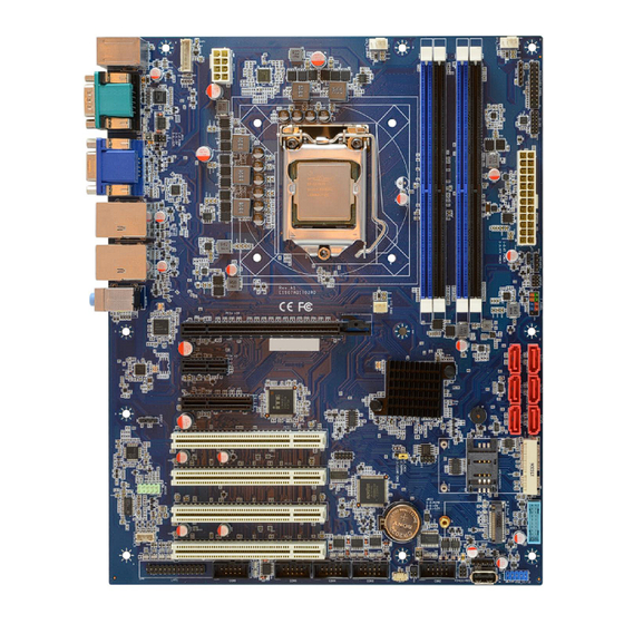
Page 14: Connector Locations
Connector Locations ATX12V1 PSUSB1 CPU1 COM1/HDMI DIMMs VGA1/DP1 ATXPWR1 LAN2 LAN1 SATA2/1 AUDIO1 SATA4/3 PCIE1 SATA6/5 PCIE2 PCIE3 MPCIE1 PCI1 JSIM1 PCI2 NGFF1 PCI3 PCI4 JUSB3... - Page 15 Jumpers, Connectors and Headers Quick Reference Table Jumpers Name Description JATATX1 AT/ATX Power Mode Selection 3x1 header, pitch 2.00mm JCMOS1 CMOS Reset 3x1 header, pitch 2.54mm JRI1 COM1 RI Function Selection 3x2 header, pitch 2.00mm JRI2 COM2 RI Function Selection 3x1 header, pitch 2.00mm Header Name...
- Page 16 Connector Name Description Type ATXPWR1 ATX Power Connector 12x2 connector ATX12V1 ATX 12V Connector 4x2 connector AUDIO1 Line-out/Line-in/Microphone 3 phone Jack COM1 Serial Port connector DB-9M CPU1 Processor Socket 1151 pin LGA socket DIMM DDR4 DIMM memory sockets 288 pin DisplayPort HDMI1 HDMI connector...
-
Page 17: Setting The Jumpers
Jumpers or headers are small pins attached to the system board. Covering two pins with a shunt closes the connection between them. The C23AX examines these jumpers to determine specific configuration information. There are two different categories of jumpers on the C23AX. -
Page 18: Jumpers
Jumpers Use the diagram below and the tables on the following pages to locate and set the on-board configuration jumpers. JATATX1: AT/ATX Power Mode Selection 1-2: AT 2-3: ATX JCMOS1: Clear CMOS 1-2: Normal 2-3: Clear CMOS... - Page 19 JRI1: COM1 RI Function Selection 1-2 closed: RI 3-4 closed : +5V 5-6 closed : +12V JRI2: COM2 RI Function Selection 1-2 closed: RI 3-4 closed : +5V 5-6 closed : +12V...
-
Page 20: Headers
Headers Use the diagram below and the tables on the following pages to locate the headers. CPUFAN1: Processor Fan header (PWM) ASSIGNMENT Tachometer JAUDIO1: Front Panel AUDIO header ASSIGNMENT ASSIGNMENT MIC-L MIC-R ACZ_DET# LINE-OUT-R MIC_Sense LINE-OUT-L LINE_Sense... - Page 21 JAUXP1: Auxiliary Panel header ASSIGNMENT ASSIGNMENT SMB_CLK CASEOPEN# ERROR_LED SMB_DATA ERROR_LED# LAN1_ACT LAN1_LINK100# LAN1_LINK1000# LAN2_ACT LAN2_LINK100# LAN2_LINK1000# JBAT1: External Battery ASSIGNMENT BAT+...
- Page 22 JCOM2A: Serial Port 2 header ASSIGNMENT ASSIGNMENT DCD (TX-) JCOM2B: Serial Port 2RS-422/RS-485 header ASSIGNMENT ASSIGNMENT 485TX- 422RX- 485TX+ 422RX+...
- Page 23 JCOM3: Serial Port 3 header ASSIGNMENT ASSIGNMENT JCOM4: Serial Port 4 header ASSIGNMENT ASSIGNMENT...
- Page 24 JCOM5: Serial Port 5 header ASSIGNMENT ASSIGNMENT JCOM6: Serial Port 6 header ASSIGNMENT ASSIGNMENT...
- Page 25 JDIO1: GPIO header ASSIGNMENT ASSIGNMENT SMB_CLK_9555 SMB_DATA_9555 11 12 5VStby JFP1: Front Panel header ASSIGNMENT ASSIGNMENT HDD LED (+) Power LED (+) HDD LED (-) Power LED (-) Reset SW Power SW...
- Page 26 JKBMS1: PS/2 Keyboard/Mouse header ASSIGNMENT MSCLK MSDATA KBDATA KBCLK JSGPIO: SGPIO header ASSIGNMENT ASSIGNMENT SGIO_LOAD SGIO_DOUT0 SGIO_CLK SGIO_DOUT1...
- Page 27 JSMB1: SMBUS header ASSIGNMENT SMBUS_CLK SMBUS_DATA SMBUS_ALERT VCC3 JSPDIF1: SPDIF header ASSIGNMENT SPDIF...
- Page 28 JSPI1: SPI header ASSIGNMENT ASSIGNMENT +3.3V SSPI_CS0#_R SSPI_SCLK_R SSPI_SO_R SSPI_SI_R SSPI_HOLD#0 JSPK1: Speaker header ASSIGNMENT...
- Page 29 JUSB1: USB3.0 header ASSIGNMENT ASSIGNMENT 10 11 SSTX2+ SSTX1+ SSTX2_ SSTX1- SSRX2+ SSRX1+ 1 20 SSRX1- VBUS2 VBUS JUSB2: USB 2.0 header ASSIGNMENT...
- Page 30 JUSB4: USB2.0 header ASSIGNMENT ASSIGNMENT JLPC1: LPC header ASSIGNMENT ASSIGNMENT LPC_AD0 +3.3V LPC_AD1 BUF_PLT_RST# LPC_AD2 LPC_FRAME# LPC_AD3 LPC_CLK LPC_SERIRQ...
- Page 31 LPT1: Parallel Port header ASSIGNMENT ASSIGNMENT STB# AFD# ERR# INIT# SLIN# ACK# BUSY SLCT SYSFAN1: System Fan 1 header (PWM) ASSIGNMENT Tachometer...
- Page 32 SYSFAN2: System Fan 2 header ASSIGNMENT Tachometer...
-
Page 33: Connectors
Connectors ATXPWR1: ATX Power Connector Connect the power supply to the 24 pin ATX Power Connector ATX12V1: ATX 12V Connector... - Page 34 CPU1: Processor Socket DIMMs...
- Page 35 JUSB3: Internal USB2.0 Connector JSIM1: SIM Card Slot MPCIE1: Full/Half size mini-PCIe Connector...
- Page 36 NGFF1: M.2 Module Slot PCIE1 PCIE2 PCIE3...
- Page 37 PCI1 PCI2 PCI3 PCI4...
- Page 38 SATA2 and 1: SATAIII (6Gb/s) connectors SATA4 and 3: SATAIII (6Gb/s) connector SATA6 and 5: SATAIII (6Gb/s) connector...
-
Page 39: Installing Memory
Firmly press the modules into the socket until it snaps into place. Adding memory modules to the C23AX is only allowed for specific configurations. Contact your Sales representative to confirm your configuration. Unreliable and incorrect operation may occur. -
Page 40: Installing Cpu
Installing CPU To properly install the processor, make sure to carefully follow these instructions: Push the lever down, unclip and lift it. Open the load plate Remove the plastic cover. Carefully align processor with notches on the socket Close the load plate, close and latch the lever... -
Page 41: Installing Heat Sink/Fan
Installing HEAT SINK/FAN The processors supported by the C23AX require the use of a heat sink/fan. Make sure to install it properly, to avoid overheating. Recommended heat sink/fans require a screwdriver to attach it to a metal bracket installed underneath (solder side) of the board. -
Page 42: Back Panel Connections
Back Panel Connections A – PS2/KB and Mouse Connector B – COM1 Connector (DB9M) C – VGA Connector D – LAN2 and USB3.0 Stacked RJ45 and USB3.0. E – LAN1 and USB3.0 Stacked RJ45 and USB3.0. F – AUDIO Stack Line-in, Speaker and Microphone Audio stack G –... -
Page 43: Chapter 3 Amibios Setup
Although you can select the device boot order in the BIOS setup, there are situations were booting from an alternate device may be required, like booting from an USB drive or DVD. The C23AX BIOS allows for boot sequence changes by using the F7 key. After powering up the board, please press F7, and a pop-up window with all available boot devices will appear. -
Page 44: Bios Setup Main Menu
BIOS Setup Main Menu The CMOS main BIOS setup menu is the first screen that you can navigate. Each main BIOS setup menu option is described later. The Main BIOS setup menu screen has two main frames. The left frame displays all the options that can be configured. - Page 45 For example: Date and Time. The <Tab> key allows you to select setup fields. Note: The <F8> key on your keyboard is the Fail-Safe key. It is not displayed on the key legend by default. To set the Fail-Safe settings of the BIOS, press the <F8> key on your keyboard. It is located on the upper row of a standard 101 keyboard.
- Page 46 HOT KEY DESCRIPTION The <F1> key allows you to display the General Help screen. Press the <F1> key to open the General Help screen. The <F2> key reloads the previous value entered. The <F3> key loads Optimal Defaults The <F4> Saves the selected settings The <Esc>...
-
Page 47: Main Setup
Main Setup When you first enter the CMOS Setup Utility, you will enter the Main setup screen. You can always return to the Main setup screen by selecting the Main tab. This screen shows some basic system information, like the BIOS Version and Identification, the processor parameters and also the date and time settings. -
Page 48: Advanced Bios Setup
Advanced BIOS Setup BIOS SETUP UTILITY Main Advanced Chipset Security Boot Save & Exit ► Trusted Computing ► ACPI Settings ► AMT Settings ► PCH-FW Configuration ► Super IO Configuration ► NCT6106D HW Monitor ► S5 RTC Wake Settings ► Serial Port Console Redirection ►... -
Page 49: Trusted Computing
► Trusted Computing Configuration Enabled or Disabled Security Device Support NO Security Device Found ► ACPI Settings Screen ACPI Settings Enable ACPI Auto Configuration Enabled or Disabled Enable Hibernation Enabled or Disabled ACPI Sleep State S3(Suspend to RAM) or Suspend Disabled ErP Function (Deep S5) Enabled or Disabled Pwr-On After PWR-Fail... -
Page 50: Super Io Configuration
► Super IO Configuration Super IO Configuration Super IO Chip NCT6106D ► Serial Port 1 Configuration Disabled or Enabled Serial Port Device Settings IO=3F8h; IRQ=4; Change Settings Auto ► Serial Port 2 Configuration Serial Port Disabled or Enabled Device Settings IO=2F8h;... -
Page 51: S5 Rtc Wake Settings
► Parallel Port Configuration Parallel Port Disabled or Enabled Device Settings IO=378h; IRQ=11; Change Settings Auto Device Mode STD Printer Mode, SPP or ECP and EPP modes ► NCT6106D HW Monitor This screen shows information about temperatures and voltages. Manual or SmartFan IV ►... - Page 52 ► CPU Configuration Settings CPU Configuration Intel® Core™ i7-6700TE CPU @ 2.40GHz CPU Signature 506E3 Microcode Patch Max CPU Speed 2400 MHz Min CPU Speed 800 MHz CPU Speed 2400 MHz Processor Cores Hyper Threading Technology Supported Intel VT-x Technology Supported Intel SMX Technology Supported...
-
Page 53: Intel Txt Configuration
Enabled or Disable CPU C states Package C State Limit C0/C1, C2,C3,C6,C7,C7S or AUTO ► Intel TXT Configuration Chipset Production Fused BiosAcm Production Fused Chipset TXT Supported Cpu TXT Supported Error code None Class Code None Major code None Minor code None ►... -
Page 54: Network Stack Configuration
► Network Stack Configuration Network Stack (UEFI) Enabled or Disabled Enabled or Disabled Ipv4 PXE Support Enabled or Disabled Ipv6 PXE Support PXE boot wait time Media Detect Count ► CSM Configuration Compatibility Support module Configuration CSM Support Enabled or Disabled CSM Module Version 07.79 Option ROM Messages... - Page 55 USB hardware delays and time-outs USB transfer time-out 1, 5, 10 or 20 sec Device reset time-out 10, 20, 30 or 40 sec Device power-up delay Auto or Manual. If set to Manual, allows to set a fixed time...
-
Page 56: Chipset Setup
Chipset Setup BIOS SETUP UTILITY Main Advanced Chipset Security Boot Save & Exit North Bridge Parameters ► System Agent (SA) Configuration ► PCH-IO Configuration : Select Screen : Select Item Enter: Select +/-: Change Opt. F1: General Help F2: Previous Values F3: Optimized Defaults F4: Save &... -
Page 57: Graphics Configuration
► System Agent (SA) Configuration System Agent Bridge Name Skylake SA PCIe Version 1.9.0.0 VT-d Supported Enabled or Disabled VT-d ► Graphics Configuration ► DMI/OPI Configuration ► PEG Port Configuration ► Memory Configuration ► GT – Power Management control ► Graphics Configuration IGFX VBIOS 1036 Skip Scanning of External Gfx Card... -
Page 58: Memory Configuration
► Memory Configuration Lists Memory parameters and allows changing Maximum Memory Frequency ► PCH-IO Configuration Intel PCH RC Version 1.9.0.0 Intel PCH SKU Name Server/Workstation SKU Intel PCH Rev ID 31/D1 ► PCI Express Configuration ► HD Audio Configuration LAN PHY Controller Enabled or Disabled Serial IRQ Mode Continuous or Quiet... - Page 59 ► HD Audio Configuration HD Audio Auto, Enabled or Disabled HD Audio 20dB, 26dB, 32dB or 36dB Amplifier Gain...
-
Page 60: Security Setup
Security Setup CMOS Password Support Two Levels of Password Protection CMOS set-up provides both an Administrator and a User password. If ONLY the Administrator’s password is set, then this only limits access to Setup and is only asked for when entering Setup. If ONLY the User’s password is set, then this is a power-on password and must be entered to boot or enter Setup. -
Page 61: Boot Setup
Boot Setup BIOS SETUP UTILITY Main Advanced Chipset Security Boot Save & Exit Boot Configuration Setup Prompt Timeout Bootup NumLock Sate [On] Quiet Boot [Disabled] Boot Option Priorities Boot Option #1 Fast Boot [Disabled] New Boot Option Policy [Default] CD/DVD ROM Drive BBS Priorities Hard Drive BBS Priorities ... - Page 62 Boot Configuration Setup Prompt Timeout Select number of seconds for Setup from 1 to 65535 Bootup NumLock State NUM-LOCK on boot: On or Off Enable or Disable Quiet Boot Boot Option Priorities Boot Option #1 Select first boot device Boot Option #2 Select second boot device CD/DVD Drive BBS If you have more than one CD/DVD, select the primary...
-
Page 63: Save & Exit Menu
Save & Exit Menu BIOS SETUP UTILITY Main Advanced Chipset Boot Security Save & Exit Save Options Save Changes and Reset Discard Changes and Reset Default Options Restore Defaults Boot Override : Sel ect Sc ree n P0: PLEXTOR DVDR PX-880SA ... -
Page 64: Appendix Atechnical Summary
Appendix A Technical Summary System Memory Map ADRESS RANGE ADDRESS RANGE (HEX) SIZE DESCRIPTION (DECIMAL) 1024K – 16777216K 100000-3FFFFFFFF 16382MB EXTENDED MEMORY 960K – 1024K F0000-FFFFFF RUNTIME BIOS 896K – 960K E0000-EFFFF BIOS RESERVED 800K – 896K C8000-DFFFF AVAILABLE TO ADAPTER ROMS 640K –... -
Page 65: Interrupt Map
Interrupt Map PRIORITY STANDARD FUNCTION System Timer Keyboard Controller Programmable Interrupt Communications Port (COM2) Communications Port (COM1) Floppy Disk Controller System CMOS/Real Time Clock ACPI Mode when enabled Available Available PS/2 Compatible Mouse Port Numeric Data Processor Prim. SATA Channel Sec. -
Page 66: Graphics Features
Graphics Features Intel® Graphics Subsystem The graphics engine built into the 6 generation processors is based on GEN 9 graphics core architecture and is able to achieve high performance at lower power consumption. It supports up to 72 Execution Units (EU) with On-Package Cache depending on the processor SKU. Some of the features are: API Support: Direct3D 12, Direct3D 11.3, Direct3D 11.2, Direct3D 11.1, Direct3D 9, Direct3D 10,Direct2D... -
Page 67: Appendix Bflash Bios Programming
Appendix B Flash BIOS Programming The C23AX uses a standard SPI FLASH BIOS. When updating your BIOS, make sure you have the correct batch file that contain all the necessary files for the upgrade. You will also need a bootable device, like a floppy, USB or hard-drive, loaded with DOS. -
Page 68: Appendix Cefi Bios And Post Codes
Appendix C EFI BIOS and POST Codes The status code, or POST code, is used to indicate progress during the boot phase. A subset of these status codes, also known as checkpoints, indicates common phases of the boot process. Checkpoints are very useful to determine the cause of a failure or problem during the pre-boot process. -
Page 69: Standard Checkpoints
Standard Checkpoints SEC Phase Status Code Description 0x00 Not Used Progress Codes 0x01 Power on. Reset type detection (soft/hard) 0x02 AP initialization before microcode loading 0x03 Northbridge initialization before microcode loading 0x04 Southbridge initialization before microcode loading 0x05 OEM initialization before microcode loading 0x06 Microcode loading 0x07... - Page 70 Status Code Description Progress Codes 0x16 Pre-memory Northbridge initialization (Northbridge module specific) 0x17 Pre-memory Northbridge initialization (Northbridge module specific) 0x18 Pre-memory Northbridge initialization (Northbridge module specific) 0x19 Pre-memory Southbridge initialization is started 0x1A Pre-memory Southbridge initialization (Southbridge module specific) 0x1B Pre-memory Southbridge initialization (Southbridge module specific) 0x1C Pre-memory Southbridge initialization (Southbridge module specific)
- Page 71 PEI Error Codes 0x50 Memory initialization error. Invalid memory type or incompatible memory speed 0x51 Memory initialization error. SPD reading has failed 0x52 Memory initialization error. Invalid memory size or memory modules don’t match 0x53 Memory initialization error. No usable memory detected 0x54 Unspecified memory initialization error 0x55...
- Page 72 Recovery Error Codes 0xF8 Recovery PPI is not available 0xF9 Recovery capsule is not found 0xFA Invalid recovery capsule 0xFB – 0xFF Reserved for future AMI error codes PEI Beep Codes # of Beeps Description Memory not installed Memory was installed twice (InstallPeiMemory routine in PEI called twice Recovery started DXEIPL was not found DXE Core Firmware Volume was not found...
- Page 73 Status Code Description 0x6D Northbridge DXE initialization (NB module specific) 0x6E Northbridge DXE initialization (NB module specific) 0x6F Northbridge DXE initialization (NB module specific) 0x70 Southbridge DXE initialization is started 0x71 Southbridge DXE SMM initialization is started 0x72 Southbridge devices initialization 0x73 Southbridge DXE initialization (SB module specific) 0x74...
- Page 74 Status Code Description 0xA3 IDE enable 0xA4 SCSI initialization is started 0xA5 SCSI reset 0xA6 SCSI detect 0xA7 SCSI enable 0xA8 Setup verifying Password 0xA9 Start of setup 0xAA Reserved for ASL 0xAB Setup input wait 0xAC Reserved for ASL 0xAD Ready to boot event 0xAE...
- Page 75 DXE Error Codes 0xD9 Error loading Boot option 0xDA Boot option is failed 0xDB Flash update is failed 0xDC Reset protocol is not available DXE Beep Codes # of Beeps Description Invalid password Some of the Architectural protocols are not available No console output devices are found No console input devices are found Flash update is failed...
- Page 76 OEM-Reserved Checkpoint Ranges Status Code Description 0x05 OEM SEC initialization before microcode loading 0x0A OEM SEC initialization after microcode loading 0x1D – 0x2A OEM pre-memory initialization codes 0x3F – 0x4E OEM PEI post memory initialization codes 0x80 – 0x8F OEM DXE initialization codes 0xC0 –...
-
Page 77: Appendix Dsata Interfaces
Appendix D SATA Interfaces The C23AX provides a total of six SATA and one mSATA connectors. SATA ports 1 through 6 support the Intel Rapid Storage Technology (Intel® RST) and allow for the following RAID modes: RAID 0 RAID 0 - Striped Disk Array without Fault Tolerance: Provides data striping (spreading out blocks of each file across multiple disk drives) but no redundancy. -
Page 78: Raid 10
RAID 10 RAID 10 is a hybrid of RAID 0 and RAID 1. This configuration is known as a striped mirrored array. See the illustration below for a graphical representation of RAID 10. RAID 5 RAID 5 – (block-level striping with distributed parity) distributes parity along with the data and requires all drives but one to be present to operate;... -
Page 79: Loading The Intel Rapid Storage Technology Raid Driver
Below is an example of the RAID Configuration Screen [MAIN MENU] 1. Create RAID Volume 2. Reset Disks to Non-RAID 3. Delete RAID Volume 4. Recovery Volume Options 5. Exit [DISK/VOLUME INFORMATION] RAID Volumes: Name Level Strip Size Status Bootable Volume0 RAID1(Mirror) N/A 1.8TB Normal... -
Page 80: Appendix Eterminology
Appendix E Terminology TERM DESCRIPTION AHCI Advanced Host Controller Interface BIOS Basic Input/Output System Column Access Strobe Central Processing Unit, also known as Processor Double Data Rate. Transfer mode between memory and computer DisplayPort Digital display interface developed by the Video Electronics Standards Association (VESA). - Page 81 MN-C23AX-01...
Need help?
Do you have a question about the C23AX and is the answer not in the manual?
Questions and answers