
Related Manuals for GarrettCom Magnum DX940

Summary of Contents for GarrettCom Magnum DX940
- Page 1 Magnum DX940 Configurable Industrial Router Installation Guide G ar r et tC om , I nc . 47 8 23 W es ting h ous e Dr i v e , F r em on t, C A 9 4 53 9, U S A...
-
Page 2: Document Notice
This manual may not be reproduced or disclosed in whole or in part by any means without the written consent of GarrettCom. DynaStar is a trademark of GarrettCom Inc. All other trademarks mentioned in this document are the property of their respective owners. -
Page 3: Warranty
Unless otherwise agreed to in writing by an authorized official of GarrettCom, products sold hereunder are not intended for use in or in connection with a nuclear facility or activity. If so used, GarrettCom disclaims all liability for nuclear damage, injury or contamination, and purchaser shall indemnify GarrettCom against any such liability, whether as a result of breach of contract, warranty, tort (including negligence) or otherwise. -
Page 4: Return Of Equipment
GarrettCom's expense for the defense of the claim. In event of a final award of costs and damages from such a suit, GarrettCom shall pay such award. In event the use of said equipment by purchaser is enjoined in such a suit, GarrettCom shall, at its own expense, and at its... -
Page 5: Ic Cs03 (Industry Canada)
DE CL E R AT IO NS Changes or modifications could void the user’s authority to operate the equipment. The user is cautioned not to change or modify this product. FCC Part 68 This device complies with part 68 of the FCC rules and the requirements adopted by the ACTA. On the bottom of this equipment is a label that contains, among other information, a product identifier in the format US:AAAEQ##TXXXX. -
Page 6: Service Personnel Warning
DE CL E R AT IO NS Industry Canada Warnings Avis d’Industrie Canada Notice: Avis: Before installing this equipment, users should Avant d’installer ce matériel, l’utilisateur doit ensure that it is permissible to be connected to s’assurer qu’il est permis de le raccorder aux the facilities of the local telecommunications installations de l’entreprise locale de company. -
Page 7: Contacting Garrettcom
CO NT ACT I NG G AR R E TT CO M CONTACTING GARRETTCOM Website: www.garrettcom.com By Mail: GarrettCom Inc. 47823 Westinghouse Drive, Fremont, CA 94539, USA Telephone: 510-438-9071 Fax: 510-438-9072 Email: support@garrettcom.com Page 7... -
Page 8: About This Manual
Callouts of this format are used to notify that a potential of electrocution exists and that a defined action could cause personal injury or death to occur. WEB ACCESS All of the DX940 installation guide is also available in a PDF format on the GarrettCom website, http://www.garrettcom.com/techsupport/hardware/userguides/dx940ug.pdf. See Datasheet Administrator Guide sections in this guide for information on other related documents. -
Page 9: Your Comments
If you find an error or have a helpful tip on the layout or informational content of this or any other GarrettCom manual please feel free to contact us via email with any problems or helpful information. All enquiries will be responded to with a correction or whatever resolution is required. - Page 10 Overview 1.1 Overview The Magnum DX940 can be configured at order time and provides connectivity to Ethernet via four 10/100 Base-T Ethernet ports or 100Mbps Fiber ports via SFP's. Additionally, two 10/100/1000 Base-T ports can be added for Gigabit connectivity or 1000Mbps fiber ports (via SFP) can be added for 1000Mbps fiber connectivity.
-
Page 11: Ch Apter 1 - Overview
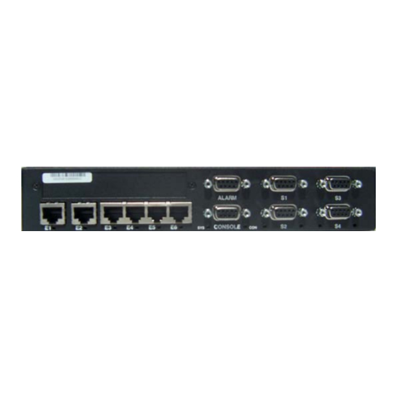
CH APTER 1 - OVERVIEW Figure 1-1. Different ports and capabilities of DX940 Figure 1-1(a) - Front View of DX940 (without the WAN port). This view shows the optional Gigabit Ethernet ports E1, E2; 10/100 Ethernet port E3 to E6 and optional serial ports S1 to 1.2.2 Power and Ground The DX940 can be ordered with a high (90 -250 VAC or VDC) or Low (24-48 VDC) voltage power... - Page 12 CH APTER 1 - OVERVIEW Figure 1-2. Rear View NOTE: The hot surfaces warning label ( ) is affixed to this device because the device is rated to operate at ambient temperatures as high as 85 (185 F). Clearly, if the device were to be installed in an environment in which temperatures at the upper end of its operating range were attained, the metal surfaces of the device would become too hot to touch.
-
Page 13: Mounting Options
CH APTER 1 - OVERVIEW Figure 1-3(a). Possible LEDs in positions "A" and "B" shown in Figure 1-3 above. The LEDs shown in Figure 1-3(a) are as follows: • E1, E2 - Gigabit Ethernet ports. • C1 - Cellular Interface. •... -
Page 14: Specifications
CH APTER 1 - OVERVIEW Specifications The following sections provide detailed information about the physical, electronic, and industrial specifications of the DX940. 1.3.1 Physical The physical dimensions and weight of the DX940 are defined in Table 1-1. Table 1-1. Physical Specifications Height: 1.75 inches (4.45 cm) Width:... -
Page 15: Power Requirements
CH APTER 1 - OVERVIEW 1.3.3 Compliance The industry compliance profile of the DX940 is defined in Table 1-3. Table 1-3. Compliance With Standards Industrial: IEEE 1613, IEC 61850-3 Emissions: EN55022A, FCC Part 15A EN55024 EN61000-4-6 (CRF) EN61000-6-2 EN61000-4-10 (MagField) EN61000-6-5 EN61000-4-11 (VDI) EN61000-4-2 (ESD) - Page 16 CH APTER 1 - OVERVIEW 1.3.5 Ports and External Connectors The ports and external connectors of the DX940 are defined in Table 1-5. Table 1-5. Ports and External Connectors Port Name Connector Description • DDS – 56/64 Kbps DDS CSU/DSU WAN connection.
- Page 17 CH APTER 1 - OVERVIEW Table 1-6. Indicators LED Name Condition Indication Green Indicates an active circuit. Indicates circuit is down or not configured (WAN DDS or properly. T1/E1 Port) Flashing Data is passing through the port. Green Port is connected to an active serial device. S1 –...
- Page 18 CH APTER 1 - OVERVIEW 1.4 Pin-outs The following subsections describe the pin-outs of the connectors used with the DX940. 1.4.1 RJ48 DDS Connection Table 1-7 defines the pin-out of the RJ48 connector used on port W1 with the DDS connection. Table 1-7.
- Page 19 CH APTER 1 - OVERVIEW 1.4.3 RJ45 for 10/100 Ethernet Ports Table 1-9 defines the pin-out of the RJ45 connector used with the DX940. RJ45 connectors are used on ports E3 though E6 for 10/100 Base-T connections to copper Ethernet-capable devices.
- Page 20 CH APTER 1 - OVERVIEW 1.4.5 DB9 (Female) – RS232 Serial Ports and Console Port Table 1-11 defines the pin-out of the DB9 female connector for the console port and for serial ports S1 - S4 when they are configured for the RS232 interface. DB9 connectors are used on RS232 serial ports S1 - S4 and the console port, for asynchronous connections.
- Page 21 CH APTER 1 - OVERVIEW 1.4.7 DB9 (Female) – RS485 Serial Ports Table 1-13 defines the pin-out of the DB9 female connector used with serial ports on the DX940 when they are configured for the RS485 interface. Table 1-13. DB9 RS485 Pin-out Signal Power Not Used...
-
Page 22: Preparing For Installation
Chapter 2 Installation This chapter provides specific procedures for installing the Magnum DX940, preparing for installation, and uninstalling the device. 2.1 Preparing for Installation The DX940 is designed to be installed in standard 19" racks, on a DIN-Rail system, or on a panel. -
Page 23: Ch Apter 2 - Install Atio N
Be sure that all the equipment you have ordered is included in the shipment. Remove the unit from the styrofoam end caps and inspect the DX940 chassis for dents or other shipping related damage. Report any damage immediately to GarrettCom customer support and DO NOT INSTALL the unit. - Page 24 CH APTER 2 - INSTALL ATIO N (that is, with I/O connections on the “wire side” of the rack). • A pair of 1.5” brackets for mounting on a panel. • bracket. A DIN-Rail mounting 2.3.1.1 Mounting in a 19” Rail System The DX device can be mounted in a 19”...
- Page 25 CH APTER 2 - INSTALL ATIO N Figure 2-2. 19” Rail Mounting brackets Figure 2-3. 19” Rail Conventional Mounting - Dimensional Drawing Page 25...
- Page 26 CH APTER 2 - INSTALL ATIO N Reverse Mounting The brackets provided for reverse mounting have an opening in their forward projecting parts to accommodate the power cable. Figure 2-4. 19” Rail Reverse Mounting brackets Figure 2-5. 19” Rail Reverse Mounting - Dimensional Drawing Page 26...
-
Page 27: Mounting On A Panel
CH APTER 2 - INSTALL ATIO N 2.3.1.2 Mounting on a Panel Each bracket for mounting on a panel attaches with two screws to the screw holes located toward the rear of the DX940 (see Figure 1-4). You can adjust the distance of the DX940 from the panel to two positions by your selection of which pair of screw holes to use in attaching the bracket to the DX940. - Page 28 CH APTER 2 - INSTALL ATIO N Figure 2-7. Panel Mounting - Dimensional Drawing 2.3.1.3 Mounting in a DIN-Rail System To mount the DX-940 on the DIN-Rail follow the following steps: 1) Purchase the SCC-DX-00-DM part which provides the DIN-Rail for DX940. 2) Unpack the ACC-DX-00-DM kit.
- Page 29 CH APTER 2 - INSTALL ATIO N 4) Remove the Panel Mount Brackets pre-installed on the system by removing the two 6-32x1/4" screws for each bracket as shown below. 5) Attach the DIN-Rail Latches to the Panel Mount Brackets with the latch plungers oriented to the rear of the DX using two 10-32x3/8"...
-
Page 30: Connecting Facility Power
CH APTER 2 - INSTALL ATIO N 2.3.2 Connecting Facility Power The DX940 comes in either high or low voltage models. The unit does not have a power on/off switch and is active when the power is connected. ELECTRICAL WARNING: Always ensure that the ground connection is made prior to connecting facility power to the DX940. -
Page 31: Console Port
CH APTER 2 - INSTALL ATIO N ELECTRICAL WARNING: Ensure that power is disconnected from wiring prior to handling! Check the voltage rating next to the power connector - verify that it matches the power source. 1. Remove the plug portion of the power connector by loosening the two captive mounting screws. -
Page 32: Connecting Network Cables
Connecting Ethernet Copper Cables The Ethernet ports are standard RJ45 ports or SFP ports. Connect the shielded Ethernet cables to the Ethernet ports. For SFP ports make sure the proper SFP is purchased from GarrettCom as well. Installing the RJ45 ports 1. -
Page 33: Maintenance
CH APTER 2 - INSTALL ATIO N 2.3.4.3 Connecting the WAN Cable The single WAN connection on the DX940 can be a DDS or a T1/E1 port. An RJ48 is used for both the DDS and the T1/E1 ports. This is a modular connector that connects the DX940 to the external telecommunications network. -
Page 34: Data Sheet
If you have not saved the original shipping container then place the unit in a box so that normal shipping activities will not cause any damage to the unit. GarrettCom has no responsibility for the product during return shipping. For more warranty information, see... - Page 35 Corporate Headquarters GarrettCom Europe GarrettCom, Inc. Waterside House 47823 Westinghouse Drive Haslar Marine Technology Park Fremont, CA 94539-7437 Haslar Rd, Gosport, Phone (510) 438-9071• Fax (510) 438-9072 Hants PO12 2AU, UK Email – Tech support – support@garrettcom.com Tel: +44 (0) 2392-603-950 • Fax: +44 (0) 2392-603-959 Email –...
Need help?
Do you have a question about the Magnum DX940 and is the answer not in the manual?
Questions and answers