Table of Contents
Advertisement
Quick Links
Advertisement
Table of Contents

Subscribe to Our Youtube Channel
Related Manuals for VIDEOMAN Digital 700


Summary of Contents for VIDEOMAN Digital 700
- Page 1 VIDEOMAN DIGITAL 700 With multiple Riser Port VIDEOMAN Systems Co. Unit 13, 112 Benaroon Rd. BELMORE NSW 2192 AUSTRALIA VIDEOMAN SYSTEMS Co. Phone : (02)9758 9509 Fax : (02)9758 9510 e-mail: info@videoman.com.au URL: www.videoman.com.au V 3.0 21/9/01...
-
Page 2: Table Of Contents
Videoman Digital 700 INDEX Contents Page Features Capabilities Normal Operation 4 – 5 Mounting Entrance Station General Wiring Guide Wiring Requirement : Single Riser Configuration Wiring Requirement : Multiple Riser Configuration Connection Diagram 10 – 11 System Programming Unit No. Programming 13 –... -
Page 3: Features
CAPABILITIES FEATURES Microprocessor driven digital Video Intercom systems guarantees powerful and flexible Module Model No. Max. No. solution and simple installation on any video intercom applications. Main Controller TMC-700 Video Entrance Station TVE-700 4 ( up to32 with TEX-700) Digital Video Entrance Station with key pads Video Handset TMN-700 Door Lock release –... -
Page 4: Normal Operation
Normal Operation With Guard Station (TVG-700 / TAG-700) Making and answering a Panic Call to the Guard Station (caretaker station) Making a Call from a Entrance Station to a Handset Press the button on handset for 2 seconds. Press again to mute beeping The system is ready to use when the Entrance Station displays on it’s LEDs. -
Page 5: Mounting Entrance Station
Mounting Entrance Station (with optional Surface Mounting Kit) General Wiring Guide ( for standard 1 channel Video/Audio and 1 channel Audio System) Distance (Metre) ~25 M ~50 M ~100 M ~300 M Between: TVE-700HD Hood - Main controller 0.44 mm 0.44 mm 2core TVE-700SD... - Page 6 Page 8 Page 9...
-
Page 7: Connection Diagram
Digital Video Intercom Connection Diagram TDE700 (Decoder) Bus In Bus Out HOUSE 8 Power Indicator Power Exit TDE700 (Decoder) TMN700 (Video handset) Bus In Bus Out HOUSE 8 Power Indicator Power Exit To Next Riser TMC700 (Main Controller) (Series of Decoders) TDE-0 TVG 4 TVE1... -
Page 8: System Programming
Door/Lift Control Unit Time Setting System Programming : to finish programming press “#” and hang up then turn main power off and on again DESCRIPTION DISPLAY on TDS-700 Power On : Activating Delay Time(sec.) on Lift Control Unit Connect Display Unit and Guard Station to Main Control (Unit Value 2Sec, Max 19 Sec) Unit. -
Page 9: System Components
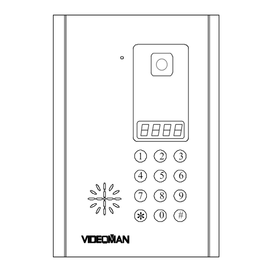
Unit No. Programming Continue. To finish programming press “#” and hang up the IMPORTANT!! Riser Memory Format – handset. On every 6 Riser output, the first Hard No. on next Turn the main power Off and On again and wait about 20 available Decoder (Next free Decoder) MUST be seconds for normal operation mode with programmed by Soft No “9999”. - Page 10 TDE-700 Decoder TVE-700 Video Entrance Station # button : Reset / Door open password entry mode button : Guard Call Power Indicator Power Exit Bus In Bus Out HOUSE 8 Microphone Adj. Speaker Volume Adjustment Dimension 310mm(W) x 56mm(H) x 180mm(D) TDE Port : to Main Controller or Next Decoder’s Bus In Bus Out...
-
Page 11: Special Extras
TMN-750 Special Extras THS-750 Same as TMN-700 and THS-700 with a keypad on hand piece Long distance interface unit for the Guard Station (TLI-700) for making a direct call to another Handsets. When guard station is located far away (up to 2 Km) this transmitter/receiver can be used for audio communication. - Page 12 Hard No. Hard No. Hard No. Hard No. Decoder Socket No. Decoder Socket No. Decoder Socket No. Decoder Socket No. Soft No. Floor Soft No. Floor Soft No. Floor Soft No. Floor Riser Dec. Plug Riser Dec. Plug Riser Dec. Plug Riser Dec.
Need help?
Do you have a question about the Digital 700 and is the answer not in the manual?
Questions and answers