Gabarron CMX15 Installation Instructions And User Manual
Digital modulating electric boilers &
electric combi boilers
Hide thumbs
Also See for CMX15:
- Installation instructions and user manual (21 pages) ,
- Installation instructions and user manual (20 pages) ,
- Installation instructions and user manual (32 pages)
Table of Contents
Advertisement
Advertisement
Table of Contents

Related Manuals for Gabarron CMX15


Summary of Contents for Gabarron CMX15
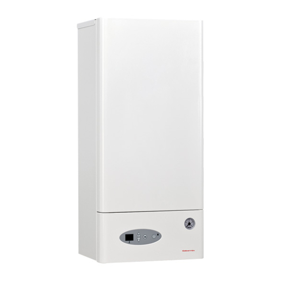
- Page 1 INSTALLATION INSTRUCTIONS AND USER GUIDE CMX15 CM15 DIGITAL MODULATING ELECTRIC BOILERS & ELECTRIC COMBI BOILERS FOR CENTRAL HEATING AND DOMESTIC HOT WATER CMX15 CM15 Please read these instructions before installing or using this appliance for the first time...
- Page 2 INDEX 6 OPERATING THE BOILER 6.1 INITIAL SWITCHING ON 1 IMPORTANT 6.2 CONTROL PANEL DESCRIPTION 2 SAFETY 6.3 DHW OPERATION 6.4 CENTRAL HEATING OPERATION 3 INTRODUCTION 6.5 ANTI-FREEZE MODE 3.1 DESIGN & OPERATION 6.6 HEATING MODULATION FEATURE 3.2 PRINCIPLE COMPONENTS 6.7 LOCKING THE CONTROL PANEL 6.8 PUMP ANTI-SEIZE FUNCTION 3.3 KEY TO COMPONENTS...
-
Page 3: Principle Components
(or underfloor system with special kit). The Gabarron CMX15 boilers are electrically heated combi boilers providing wet central heating through a standard radiator system (or underfloor system with special kit) and domestic hot water (DHW) delivered from an integral unvented store at mains water pressure. -
Page 4: Installation
4 INSTALLATION IMPORTANT PRE- INSTALLATION POINTS In order to ensure the successful installation and operation of your Gabarron boiler please consider the following points before commencing. SITING THE BOILER Wall and fixings must b suitable to WARNING support the total weight; CMX boiler when full is 120 kg, CM boiler when full is 50 kg. -
Page 5: Hot Water System
HOT WATER SYSTEM The installation should be carried out by a person certified Competency to install unvented hot water system is as competent for the installation of unvented hot water required. systems in accordance with current building regulations. Any existing system and controls (e.g. shower) must be Installation should also be in accordance with the relevant suitable to operate at mains water pressure. -
Page 6: Dimensions And Connections
4.3 LOCATION WARNING INSTALL UPRIGHT ON A WALL SUITABLE TO SUPPORT THE TOTAL WEIGHT OF THE BOILER WHEN FULL OF WATER – 120 kg. The location should be clean and dry with no presence of gases, explosives or flammable objects. It is not suitable for installation outside and should be protected from moisture and frost. -
Page 7: Mounting Bracket
4.5 CLEARANCES A: 50 mm B: 10 mm C: 200 mm The clearances around the boiler as shown above must be observed for correct operation. A minimum of 200mm clearance must be maintained underneath the boiler to allow replacement of the heating elements if required. -
Page 8: Water Connections
Always use assistance if required. Wear suitable cut resistant gloves when handling the appliance. Ensure safe lifting techniques are used. Do not lift the appliance by attached pipe-work or components. When lifting the boiler ensure that the fixing elements and the wall have a sufficient load-bearing capacity. Check the quality of the wall. -
Page 9: Dhw Discharge Pipe-Work
Cold Water Inlet A ½” connection is provided for connection to 15mm pipe. An integral isolating valve provides control of the incoming water supply. An internal non-return valve prevents possible back-flow should the water main fail. CAUTION: If the incoming water pressure exceeds 5 bar it is necessary to install a Pressure Reducing Valve set at 2.5 bar on the water main into the dwelling. -
Page 10: Electrical Connections
4.10 ELECTRICAL CONNECTIONS Connection to Mains Supply The CM15 and CMX15 boilers must be installed in premises having a system impedance of not more than 0.25 + j0.25Ω. The CM15 and CMX15 boilers comply with the technical requirements of BS EN 61000-3-3. - Page 11 WARNING THE SUPPLY CABLE TO THE BOILER SHOULD BE OF SUFFICIENT SIZE TO CARRY THE LOAD CAPACITY REQUIRED. IT SHOULD BE WIRED THROUGH A LINKED ISOLATOR SWITCH WITH MINIMUM CONTACT GAPS OF 3mm IN EVERY POLE AND PROTECTED BY A SUITABLY RATED CIRCUIT BREAKER MCB/RCD Install the necessary electrical protections as indicated in the current regulations.
-
Page 12: Limiting Boiler Maximum Output
5 COMISSIONING 5.1 LIMITING BOILER MAXIMUM OUTPUT The boiler is supplied for operation on maximum heat output of 15kW. The output can be rated below this maximum to match the heat load required. WARNING: ON INSTALLATIONS WHERE THE INCOMING POWER SUPPLY IS NOT CAPABLE OF MAXIMUM LOAD THE BOILER CONTROL MUST BE RE-CONFIGURED TO LIMIT THE OUTPUT BEFORE SWITCHING ON. - Page 13 3 kW 13.0A 3 kW -‐ -‐ 13.0A LIMITATION O F O UTPUT O N M ODELS C M15 & C MX15 C onnection S INGLE P HASE 2 30V~ Connection ...
-
Page 14: Control Panel
Turn on the boiler with the on/off switch located at the back of the boiler as shown. Mains connection terminals remain live even if the on/off switch is turned off. 6.2 CONTROL PANEL DESCRIPTION MODELS CMX15 Increases Heating water DHW. ... -
Page 15: Domestic Hot Water Operation
MODELS CM15 Increases heating water temperature Keyboard lock Heating water indicator temp. and other messages On / Off button Block / Unblock Red dot shows heating heating ... - Page 16 6.4 CENTRAL HEATING OPERATION First ensure that any external controls such as room thermostat or time clock are demanding heat. To select the heating function, push the button. Pushing again will switch the function off and return display to just a red dot.
-
Page 17: Troubleshooting
7 TROUBLESHOOTING 7.1 POSSIBLE FAULTS & SOLUTIONS Problem Possible cause Solution No power to boiler. Check incoming power supply. No power. Check boiler control switch is on. Boiler will not start (See Section 6.1.) Heating overheat. Switch tripped. Locate switch and reset. (See Section 7.2) DHW Overheat switch tripped. -
Page 18: Checking Rated Heat Output
7.2 OVERHEAT LOCK-OUT & RE-SETTING Central heating overheat. If the boiler detects a overheat condition of 100ºC (80ºC if adapted floor heating ) in the central heating circuit a safety thermal limit switch will operate and switch the boiler off disabling all functions including DHW production. The cause of the overheat should be investigated. -
Page 19: Main Components
9 MAINTENANCE & CARE Gabarron electric boilers do not require any special maintenance for a prolonged and trouble-free life however the following points should be observed: -Check and maintain the heating system pressure between 1 & 1.5 bar when cold. Frequent re-filling of the system could cause scaling and corrosion and should be avoided. -
Page 20: Technical Data
11 TECHNICAL DATA CMX15 CM15 Frequency Connection 3x400V+N~ ¿ ¿ Output limited to 15kW; Maximum intensity 21.7 21.7 Output limited to 13kW; Maximum intensity 21.7 21.7 Output limited to 12kW; Maximum intensity 21.7 21.7 Output limited to 11kW; Maximum intensity 21.7... -
Page 21: Ec Declaration Of Conformity
Digital Modulating Electric Boiler Trade Mark: GABARRÓN Models: CM15; CM18; CMX15; CMX18; CMX15P; CMX18P has been manufactured to the technical specifications of the product and conforms in all respects to the relevant standards and regulations in force and especially to : Safety:... -
Page 22: Wiring Diagrams
12 WIRING DIAGRAMS 21 ... - Page 23 NOTES The symbol on the product or in its packaging indicates that this product may not be treated as household waste. Instead it shall be handed over to the applicable collection point for the recycling of electrical and electronic equipment. By ensuring this product is disposed of ...
- Page 24 ELNUR UK Ltd. Unit 1, Brown Street North Leigh, Lancashire WN7 1BU www.elnur.co.uk Customer Service Department: Telephone +44(0)1942 670119 technical@elnur.co.uk Manufactured by: ELNUR, S.A. Madrid, Spain www.elnur-global.com export@elnur-global.com Management System International Certifications: As a part of the policy of continuous product improvement Elnur reserves the right to alter specifications without notice. INSTALLATION INSTRUCTIONS AND USER GUIDE WEB VERSION...
Need help?
Do you have a question about the CMX15 and is the answer not in the manual?
Questions and answers