Table of Contents
Advertisement
Advertisement
Table of Contents

Related Manuals for Simrad V5035


Summary of Contents for Simrad V5035
- Page 1 V5035 Operator and Installation Manual ENGLISH pro.simrad-yachting.com...
-
Page 3: General Information
The entire contents of this instruction manual, including any future updates, revisions, and modifications, shall remain the property of SIMRAD at all times. Unauthorized copies or reproduction of this manual, either in part or whole, in any form of print and electronic media, is prohibited. - Page 4 The onboard documentation as described in Appendix C can be used to assist reflecting software maintenance records. VII. Type Approval The SIMRAD V5035 AIS transponder complies with applicable international standards and is type approved in accordance with the European Marine Equipment Directive.
- Page 5 VIII. Declaration of Conformity Hereby, SIMRAD declares that this V5035 is in compliance with the essential requirements and other relevant provisions of Directive 96/98/EC. IX. Disposal Instruction Do not dispose of this device with unsorted waste. Improper disposal may be harmful to the environment and human health.
-
Page 6: Table Of Contents
Configuring the V5035 Operation Panel description Display modes Entering text Menu tree overview Messages Inland messages Navigation status Ship setting Inland setting Transceiver Sys Config Diagnostics Technical specifications Applicable standards VHF transceiver DSC receiver Contents | V5035 Operator and Installation Manual... - Page 7 Mounting template (not to scale) VHF antenna GPS antenna Pilot plug Troubleshooting GN70/MX61X AIS operation Target symbols Viewing information about AIS targets Vessel filter Vessel alarms Abbreviations Appendix A 112 Appendix B 114 Appendix C Contents | V5035 Operator and Installation Manual...
-
Page 8: What Is Ais
Is provided by aids-to-navigation authorities to enable the ship to shore / shore to ship transmission of information. Networked AIS Base Stations can assist in providing overall maritime domain aware- ness. What is AIS? | V5035 Operator and Installation Manual... - Page 9 It is typically used on life rafts. • AIS on Search and Rescue (SAR) Aircraft: Used on airplanes and helicopters to assist search and rescue opera- tion. What is AIS? | V5035 Operator and Installation Manual...
-
Page 10: System Overview
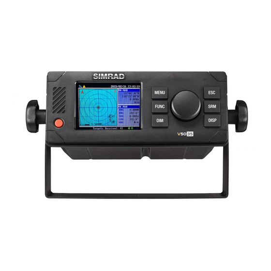
It is an excellent choice for SOLAS vessels, commercial vessels, and professional vessels. The V5035 consists of a transceiver radio unit, an integrated GPS re- ceiver, a controller unit, and a color 3.5” LCD display with menu key- pads. -
Page 11: Main Features
IMO Compliant Class-A AIS system • Supplied as a standalone system with junction-box, GPS antenna and Pilot Plug • Easily integrates with Simrad GPS and Charting systems via NMEA2000 interface. • Perfect complement to Simrad IMO GPS/GNSS systems (GN70, MX610, MX612) •... -
Page 12: Installation
USB cable Junction box 000-12324-001 Pilot Plug Asy. 000-12325-001 U-bracket mounting kit 000-12327-001 37-pin extension cable 000-12328-001 3-pin power cable 000-12329-001 Panel mount holder kit 000-12330-001 User manual 988-10838-001 12 | Installation | V5035 Operator and Installation Manual... -
Page 13: Installation Procedures
Connect all required cables to the main transponder unit Power on the main transponder unit Complete configuration settings Perform system functional test RF cable requirements The following RF cables are recommended to install the V5035 - . • VHF Antenna Cable Type: 5D-FB or equivalent Connector: SO-239 (Male) •... -
Page 14: Vhf Antenna Installation
The GPS antenna must be installed where it has a clear view of the sky, so that it may access the horizon freely with 360° degrees, with a vertical observation of 5 to 90 degrees above the horizon as illustrated below. 14 | Installation | V5035 Operator and Installation Manual... -
Page 15: Mounting Simrad V5035
• The transponder should not be installed near flammable or hazard- ous environments. • The AIS transponder should be installed at least 0.5 m away from magnetic compasses. Mounting Transponder | 15 Installation | V5035 Operator and Installation Manual... - Page 16 From the rear, install the mounting brackets with the M3X8 screws. Apply the mounting bracket screw (brackets are directional, ensure correct one is fitted to each side) on each side for a firm fix. Panel mounting (1) Panel mounting (2) 16 | Installation | V5035 Operator and Installation Manual...
- Page 17 Mounting junction box Mounting junction box (1) Mounting junction box (2) | 17 Installation | V5035 Operator and Installation Manual...
- Page 18 Pin 1 Tx A Pin 2 Pin 3 Pin 4 Tx B White Pin 5 Rx A Black Pin 6 Rx B Green Pin 7 Pin 8 Pin 9 Shield (Ground) 18 | Installation | V5035 Operator and Installation Manual...
- Page 19 Connecting to MX5035 Junction Box Use the following guidelines to connect the Pilot Plug to the V5035 Junction box. Refer to External Connectors (Junction Box) page 21. To transponder main unit Pilot plug PILOT_IN A connects to Rx A (Black)
-
Page 20: External Connectors (Transponder Main Unit)
¼ Note: Some boats require frame ground connection of all electronic devices on the ship frame. 20 | Installation | V5035 Operator and Installation Manual... -
Page 21: External Connectors (Junction Box
SEN3_IN GND Sensor 3 ground Connect to data sources such as heading, gyro, or other type Sensor 3 SEN3_IN A Sensor 3 input A of sensors. SEN3_IN B Sensor 3 input B | 21 Installation | V5035 Operator and Installation Manual... - Page 22 ECDIS. DISP_OUT B DISP output B BLUE_SIGN A Connect to a blue sign switch. Blue sign BLUE_SIGN B ¼ Note: RTCM-SC-104 beacon input is currently not implemented by the DGPS_IN input. 22 | Installation | V5035 Operator and Installation Manual...
-
Page 23: Connecting Extension Cable
Connecting extension cable Use the 37-pin- extension cable (1.8M) provided in the package connect V5035 to the junction box. Connecting V5035 with Junction box | 23 Installation | V5035 Operator and Installation Manual... -
Page 24: Configuring The V5035
2013/01/17 07:18:11 MENU MAIN MENU SHIP SETTING MESSAGES OWN SHIP NAV. STATUS SHIP SETTING VOYAGE CPA/TCPA TRANSCEIVER SYS CONFIG SET MMSI/IMO/ENI RETRY TIMES DIAGNOSTICS AIS MODE Dangerous Targets :0 Own ship 24 | Installation | V5035 Operator and Installation Manual... - Page 25 B. If IMO identification number is applicable, select main menu item Set MMSI/IMO/ENI to setup IMO number. 2013/01/17 22:43:39 SET MMSI/IMO/ENI MMSI [000000000] [000000000] Targets Received: 10 IMO setting For more information please refer to SHIP SETTING, page 55. | 25 Installation | V5035 Operator and Installation Manual...
-
Page 26: Operation
4. Dangerous target list 5. Own ship detail 6. GPS satellite information 7. Region setting list Emergency SRM broadcast Cancel/Back to main menu, or press and hold for 3 seconds to access alarm list 26 | Operation | V5035 Operator and Installation Manual... - Page 27 The Transmission & Reception bar constantly displays real time status of transmissions and receptions on any display modes. The 3 default displayed messages are received AIS targets, dangerous targets, and Tx power level. | 27 Operation | V5035 Operator and Installation Manual...
- Page 28 SART or MOB target is received Function zoom in/out Icon target selected (Radar view only) SART/MOB Indicate the system is running Inland mode Inland mode Indicate Blue Sign device is connected Blue sign 28 | Operation | V5035 Operator and Installation Manual...
-
Page 29: Display Modes
SIMRAD: 15 AIS target list Shows all received ship data (Refer to AIS Targets, page 49) Dangerous target Shows all dangerous AIS targets pres- list ently (Refer to Dangerous List, page 54) | 29 Operation | V5035 Operator and Installation Manual... - Page 30 Without GPS reception, own ship needs to be located manually. AIS target Color: Black Ship equipped with AIS system in the surrounding sea will appear on the radar view as an AIS target. 30 | Operation | V5035 Operator and Installation Manual...
- Page 31 Color: Red / Cross The icon will be displayed if any SART message is sent out. Base station Color: Green The icon will be displayed when any base station is in the reception range. | 31 Operation | V5035 Operator and Installation Manual...
- Page 32 System and therefore should not be used for navigation. The information provided by the coastline map is for reference only and should be used together with other navigation sources and devices. 32 | Operation | V5035 Operator and Installation Manual...
- Page 33 The chart orientation is fixed and true north is always pointing up. COURSE UP The orientation is determined by the own ship’s traveling course. HEAD UP The orientation is determined by the direc- tion of own ship’s bow. | 33 Operation | V5035 Operator and Installation Manual...
-
Page 34: Entering Text
System is now in character selection mode as the cursor position is high- lighted. Turn the knob to pick an available character and press the knob for character selection. “ ÷ & ‘ < > ¼ Note: Space is first character for selection. 34 | Operation | V5035 Operator and Installation Manual... - Page 35 2: Select a character position Turn knob to move Press to start left or right editing 3: Pick character Turn knob to select Press to character confirm | 35 Operation | V5035 Operator and Installation Manual...
- Page 36 4. Confirm and save To save entered text, press and hold the knob for 2 seconds. 36 | Operation | V5035 Operator and Installation Manual...
-
Page 37: Menu Tree Overview
MEMORY TEST SET MMSI/IMO/ENI (page 58) SENSOR PORT RETRY TIMES (page 60) TFT-PANEL AIS MODE (page 60) KEYBOARD TEST GPS STATUS TRANSCEIVER COMMUN. TEST PANEL TEST VERSION * Inland mode only | 37 Operation | V5035 Operator and Installation Manual... - Page 38 LR INBOX Log of received inquiry messages from other INLAND MESSAGES ETA/RTA INBOX Log of ETA(RFM21), RTA(RFM22) message received ETA OUTBOX Log of ETA(RFM21) sent CREATE ETA MSG Create ETA(RFM21) message 38 | Operation | V5035 Operator and Installation Manual...
- Page 39 VESSEL DATA SET. Configure Vessel data Configure ETA ETA SETTING NUMBER OF PERSON Set number of persons BLUE SIGN SET. Set Blue sign settings Set report rate settings REPORT RATE SET. | 39 Operation | V5035 Operator and Installation Manual...
- Page 40 SENSOR PORT Transmission port test TFT-PANEL Screen panel Button test KEYBOARD TEST GPS STATUS GPS positioning status TRANSCEIVER Transponder status Test communication COMMUN. TEST PANEL TEST Test Panel VERSION Firmware version 40 | Operation | V5035 Operator and Installation Manual...
-
Page 41: Messages
Outbox SRM You can read all sent SRM messages under OUTBOX. Turn the knob to traverse the message list and highlight your choice. Read the message content by pressing the knob. | 41 Operation | V5035 Operator and Installation Manual... - Page 42 Edit and send Broadcast SRM Addressed SRM ADDRESSED SRM means a SRM addressed to a certain MMSI num- ber which can be selected from the target list or input manually. By 42 | Operation | V5035 Operator and Installation Manual...
- Page 43 These are requests for infor- mation from a distant base station beyond normal AIS operation range. LONG RANGE SRM holds all received Long Range Interroga- tion messages. Turn the knob to traverse the message list. | 43 Operation | V5035 Operator and Installation Manual...
-
Page 44: Inland Messages
The received messages of ETA (RFM21) and RTA (RFM22) can be read in the ETA/RTA Inbox. Turn the knob to traverse the message list and highlight your choice. Read the message content by pressing the knob. 44 | Operation | V5035 Operator and Installation Manual... - Page 45 After ETA (RFM21) transmitted, if no RTA (RFM22) is received within 15 minutes, transponder will transmit ETA (RFM21). After the addressee is selected, you can configure the ETA message. | 45 Operation | V5035 Operator and Installation Manual...
- Page 46 Here you can either pick the address- ee from the list or press ESC to leave the target list to enter the MMSI number manually or broadcast the POB message without specifying any addressee. 46 | Operation | V5035 Operator and Installation Manual...
- Page 47 STRONG, HEAVY WIND DIRECTION NW Dangerous Targets :0 Dangerous Targets :0 EMMA warning log and message content Use the knob to select a message and press the knob to display message content. | 47 Operation | V5035 Operator and Installation Manual...
-
Page 48: Navigation Status
SENSOR STATUS Dangerous Targets :0 Own ship This option displays the full information on your ship, including both dynamic and static data. Turn the knob to change between dynamic and static information. 48 | Operation | V5035 Operator and Installation Manual... - Page 49 8. 211111461 39.97 350.8° TCPA pass 211111161 39.54 351.8° 10. TEST02 91.62 RAIM Not in use Manoeuvre Ind. not available Dangerous Targets :0 Dangerous Targets :0 AIS targets and details | 49 Operation | V5035 Operator and Installation Manual...
- Page 50 Dangerous Targets :0 Adding friend ship In the screenshot above, the block A indicates the current sorting method. By MMSI, in ascending order By direction, in ascending order By distance, in ascending order 50 | Operation | V5035 Operator and Installation Manual...
- Page 51 If the region information is unchangeable, saving does not change the original information. Alarm list V5035 features SART/MOB alarm that can appear any time during operation. When SART/MOB message is received, the icon will appear in the status bar with beeping sounds from the beeper.
- Page 52 2. 32. Heading lost/invalid Confirm Message? 3. 35. No valid ROT information 3. 35. No valid ROT information CANCEL TX malfunction Targets Received: 10 Figure 47 Alarm List and acknowledgement Alarm list and acknowledgement 52 | Operation | V5035 Operator and Installation Manual...
-
Page 53: Alarm History
COG STATUS INT. COG / EXT. COG / LOST SOG STATUS INT. SOG / EXT. SOG / LOST HEADING STATUS VALID / LOST ROT STATUS VALID / OTHER ROT / LOST | 53 Operation | V5035 Operator and Installation Manual... - Page 54 MOB list entries. 2013/01/17 17:04:38 2013/01/17 17:04:39 MOB LIST MOB LIST [000]-- ID ------ NAME -------------------------- [000]-- ID ------ NAME -------------------------- DELETE ADD NEW TX POWER LEVEL: 12.5W TX POWER LEVEL: 12.5W 54 | Operation | V5035 Operator and Installation Manual...
-
Page 55: Ship Setting
There are a total of 5 submenus. 2013/01/17 07:18:11 MENU MAIN MENU SHIP SETTING MESSAGES OWN SHIP NAV. STATUS VOYAGE SHIP SETTING CPA/TCPA TRANSCEIVER SET MMSI/IMO/ENI SYS CONFIG RETRY TIMES DIAGNOSTICS AIS MODE Dangerous Targets :0 | 55 Operation | V5035 Operator and Installation Manual... - Page 56 Ship setting in SOLAS mode (left) and inland mode (right) ¼ Note: if Ship Type is Tanker, by regulation, whenever the ship naviga- tion status is “Moored”, the transponder’s transmission power is automatically changed to 1W for safety measures. 56 | Operation | V5035 Operator and Installation Manual...
- Page 57 To set up number of person on board, please go to INLAND SETTING/NUMBER OF PERSON. By CONVOY EXTENSION, the dimensions of the vessel are set to the maximum rectangular size of the convoy when operating in inland AIS mode. | 57 Operation | V5035 Operator and Installation Manual...
- Page 58 This section is password protected and can only be accessed using the password (page 66). SOLAS Mode This submenu provides access to set MMSI and IMO. Use the knob to choose the menu option either MMSI or IMO. 58 | Operation | V5035 Operator and Installation Manual...
- Page 59 “SOLAS Mode” on page 58. 2013/01/17 22:43:39 2013/01/17 22:43:39 CHANGE MMSI/IMO/ENI ENI SETTING [A1234567] MMSI [200000000] [000000000] Targets Received: 10 Dangerous Targets :0 ENI setting ¼ Note: When setting is done, press ESC to exit. | 59 Operation | V5035 Operator and Installation Manual...
-
Page 60: Inland Setting
Blue Cones - The number of blue cones or blue flag status for the cargo (1, 2 or 3 blue cones, or blue flag). • Load Status - ‘Loaded’, ‘Unloaded’, ‘Unknown’ • Quality of Speed, Course and heading information - will be shown as 60 | Operation | V5035 Operator and Installation Manual... - Page 61 To save the settings, press MENU or ESC and the system will ask whether the changes should be saved. Select OK to save or CANCEL to discard and return to main menu. | 61 Operation | V5035 Operator and Installation Manual...
-
Page 62: Transceiver
<ENABLE> Dangerous Targets :0 Blue sign switch setting Report Rate Setting Set V5035’s report rate. Selectable report rates are AUTO/ 10 SEC./ 5 SEC./ 2 SEC.. Transceiver This section is password protected and can only be accessed using the password (page 66). -
Page 63: Sys Config
Sys Config System configuration provides access to user configurable prefer- ences for V5035. All user settings are stored within the transponder and will be maintained if the power supply is switched off. After the setting is done, press MENU or ESC and the system will ask whether the changes should be saved. - Page 64 Longitude [057]°[00]’[00]”<W> RADAR VIEW ORIENTATION MODE <NORTH UP> Targets Received: 10 Radar view setting In this view setting, RADAR VIEW ORIENTATION has NORTH UP/ COURSE UP / HEAD UP view modes. 64 | Operation | V5035 Operator and Installation Manual...
- Page 65 Baud rate setting Factory This section is password protected and can only be accessed using the password (page 66). Press knob to confirm your choice and the following settings will be | 65 Operation | V5035 Operator and Installation Manual...
- Page 66 To save the settings, press MENU or ESC and the system will ask whether the changes should be saved. Select OK to save or CANCEL to discard and return to main menu. 66 | Operation | V5035 Operator and Installation Manual...
- Page 67 TX POWER LEVEL: 12.5W ¼ Note: Only AIS channel numbers can be entered for TX channel. Channel 2078, 2088, and the current channel used in the region can- not be used. | 67 Operation | V5035 Operator and Installation Manual...
- Page 68 SHIP SETTING LR BCST SET. hold KNOB for confirmation. TRANSCEIVER DEST. TABLE SET. SYS CONFIG [ **** ] ALARMS SETTING DIAGNOSTICS VSWR SETTING TX POWER LEVEL: 12.5W TX POWER LEVEL: 12.5W 68 | Operation | V5035 Operator and Installation Manual...
-
Page 69: Diagnostics
Dangerous Targets: 2 Dangerous Targets: 2 Keyboard test GPS Status: This option provides GPS satellite status information. Green indicates satellite being used for GPS fix. Red indicates satel- lite not being used. | 69 Operation | V5035 Operator and Installation Manual... - Page 70 A MMSI number. Then press MENU, ESC or FUNC and click “OK” to start the transmission of Message 10. Only Class A units with GPS fix are listed 70 | Operation | V5035 Operator and Installation Manual...
- Page 71 Version Provide model name, hardware information, delivered firmware ver- sion on the unit, etc. When finished, press ESC to exit. 2013/01/17 22:43:39 VERSION PRODUCT V5035 - AIS Class A V5035 - AIS Class A V1.0.6.41 FIRMWARE V1.0.6.39 COMPANY Alltek Marine...
-
Page 72: Technical Specifications
< -107 dBm @ BER < 10-2 Spurious Response Rejection ≧ 70 dB for signal @ -104 dBm; BER ≦ 1 % Blocking ≧ 84 dB for signal @ -104 dBm; BER ≦ 1 % 72 | Technical specifications | V5035 Operator and Installation Manual... -
Page 73: Gps Receiver (Internal)
GPS Antenna Connector TNC (Female) VHF Antenna Connector SO-239 (Female) Sensor Interfaces 1 to 3 IEC 61162-1 or -2 Pilot / Auxiliary IEC 61162-2 External Display IEC 61162-2 Long-range IEC 61162-2 | 73 Technical specifications | V5035 Operator and Installation Manual... -
Page 74: Environmental
This is the reason the NMEA2000 PGN list covers both Class A and Class B related information. Transmit Description 59392 ISO Acknowledgment 59904 ISO Request 60928 ISO Address Claim 74 | Technical specifications | V5035 Operator and Installation Manual... - Page 75 AIS Class B “CS” Static Data Report, Part A 129810 AIS Class B “CS” Static Data Report, Part B Receive Description 59392 ISO Acknowledgment 59904 ISO Request 60928 ISO Address Claim | 75 Technical specifications | V5035 Operator and Installation Manual...
-
Page 76: Mechanical Dimensions
Mechanical dimensions V5035 Transponder main unit Front (size: mm) Side (size: mm) 76 | Mechanical dimensions | V5035 Operator and Installation Manual... - Page 77 Back (size: mm) Bottom (size: mm) | 77 Mechanical dimensions | V5035 Operator and Installation Manual...
-
Page 78: Junction Box
Junction box Extension cable 78 | Mechanical dimensions | V5035 Operator and Installation Manual... -
Page 79: Mounting Template (Not To Scale)
Mounting template (not to scale) VHF antenna | 79 Mechanical dimensions | V5035 Operator and Installation Manual... -
Page 80: Gps Antenna
GPS antenna 80 | Mechanical dimensions | V5035 Operator and Installation Manual... -
Page 81: Pilot Plug
Pilot plug | 81 Mechanical dimensions | V5035 Operator and Installation Manual... -
Page 82: Troubleshooting
AIS range seems VHF antenna and Check VHF antenna too low cabling and cable installation Sensor ports not Cable installation Check related wiring response Data port not Cable installation Check related wiring response 82 | Troubleshooting | V5035 Operator and Installation Manual... -
Page 83: Gn70/Mx61X Ais Operation
GN70/MX61X AIS operation The GN70/MX610/MX612 CDU can display AIS targets provided by the V5035 AIS transponder by pressing the AIS hot key. You can zoom-out by turning the ROTARY KNOB counter-clockwise or zoom- in by turning it in clockwise direction. AIS targets can be displayed as overlay on the plotter screen. -
Page 84: Target Symbols
Scroll to the desired AIS target, press ENT to show the vessel details. Press the ENT key to close. To exit, press the CLR a few times or any hot key. 84 | GN70/MX61X AIS operation | V5035 Operator and Installation Manual... -
Page 85: Vessel Filter
Press the MENU key to bring up the quick menu. Scroll to Vessels Filter… menu, press ENT. Select desired action by scrolling to it and pressing ENT to leave a check mark. Scroll to SAVE, press ENT. | 85 GN70/MX61X AIS operation | V5035 Operator and Installation Manual... -
Page 86: Vessel Alarms
Controls whether an alarm shall be activated when a message is received from an AIS target. ¼ Note: Please refer to the GN70/MX61x User manual for more AIS operation. 86 | GN70/MX61X AIS operation | V5035 Operator and Installation Manual... -
Page 87: Abbreviations
System Electronic Chart System EGNOS European Geo-stationary Navigational Over- lay System Electronic Navigation Chart EPFS Electronic Position Fixing System EPIRB Electronic Position Indicating Radio Beacon Escape Estimated Time of Arrival External | 87 Abbreviations | V5035 Operator and Installation Manual... - Page 88 INFO Information ITU-R International Telecommunications Union - Radio Knots Latitude Liquid Crystal Display Longitude Long Range Maritime Equipment Directive Minute Minimum Keyboard and Display MMSI Maritime Mobile Service Identity Man Overboard 88 | Abbreviations | V5035 Operator and Installation Manual...
- Page 89 Tx / Rx Transmit / Receive Ultra High Frequency Universal Serial Bus Universal Time Co-ordinate VHF Data Link Very High Frequency VSWR Voltage Standing Wave Ratio WAAS Wide Area Augmentation System | 89 Abbreviations | V5035 Operator and Installation Manual...
-
Page 90: Appendix A
Appendix A IEC 61162-2 Data Interface The V5035 Class A AIS Transponder provides 2 types of IEC 61162-2 data interfaces for user applications. The first interface type includes 3 input-only sensor data ports and the second interface type includes 4 bidirectional input/output ports. Data port for each inter- face type will be described in the following section below. -
Page 91: Bidirectional Data Ports
60mA, and the minimum differential output swing under 100 Ω load can be 2.3V. A and B Signal Lines Refer to sections Sensor Data Input Ports (previous page) and Bidi- rectional Data Ports above. | 91 Appendix A | V5035 Operator and Installation Manual... - Page 92 Refer to sections Sensor Data Input Ports (previous page) and Bidi- rectional Data Ports above. Hardware Input/Output Circuit Refer to sections Sensor Data Input Ports (previous page) and Bidi- rectional Data Ports above. 92 | Appendix A | V5035 Operator and Installation Manual...
- Page 93 PAMC Proprietary Long Range Port (optional) Long range 61162-2 Input LRI,LRF Output LRF, LR1,2,3 DGNSS Data Port DGNSS Data Correction data information (optional) 823-2 BIIT BIIT Output Port CH10 NC Relay | 93 Appendix A | V5035 Operator and Installation Manual...
- Page 94 Format Description Remark Total number of sentences needed to transfer the message Sentence number Sequential message identifier The MMSI of the destination AIS unit for the ITU-R xxxxxxxxx M.1371 message 94 | Appendix A | V5035 Operator and Installation Manual...
- Page 95 ACK – Acknowledge Alarm This sentence is used to acknowledge an alarm condition reported by a device. $--ACK,xxx*hh<CR><LF> Field No. Format Description Remark Unique alarm number (identifier) at alarm source | 95 Appendix A | V5035 Operator and Installation Manual...
- Page 96 Total number of sentences needed to transfer the message Sentence number Sequential message identifier AIS channel for broadcast of the radio message ITU-R M.1371 Message ID s—s Encapsulated data Number of fill-bits 96 | Appendix A | V5035 Operator and Installation Manual...
- Page 97 ID number of most likely failed satellite ignored Probability of missed detection for most likely ignored failed satellite Estimate of bias on most likely failed satellite ignored Standard deviation of bias estimate ignored | 97 Appendix A | V5035 Operator and Installation Manual...
- Page 98 $--GLL, llll.ll, a, yyyyy.yy, a, hhmmss.ss, A, a *hh<CR><LF> Field No. Format Description Remark llll.ll, a Latitude, N/S yyyyy.yy, a Longitude, E/W hhmmss.ss UTC of position Status, A=data valid V=data invalid Mode indicator 98 | Appendix A | V5035 Operator and Installation Manual...
- Page 99 A = automatic, allowed to automatically switch 2D/3D Mode: 1 = fix not available, 2 = 2D, 3 = 3D xx,xx,xx,xx,xx, xx,xx,xx,xx,xx, ID numbers of satellites used in solution xx,xx PDOP HDOP VDOP | 99 Appendix A | V5035 Operator and Installation Manual...
- Page 100 LRI and LRF (see the LRI-sentence). $--LRF,x,xxxxxxxxx,c—c,c—c,c—c*hh<CR><LF> Field No. Format Description Remark Sequence number MMSI of requestor xxxxxxxxx c—c Name of requestor c—c Function request c—c Function reply status 100 | Appendix A | V5035 Operator and Installation Manual...
- Page 101 Vessel speed Ignored Speed reference,B/M/W/R/P (see Note) Ignored Vessel set, degrees true Ignored Vessel drift (speed) Ignored Speed units, K = km/h; N = knots; ignored S = statute miles/h | 101 Appendix A | V5035 Operator and Installation Manual...
- Page 102 (for example EPV, SSD). $--SPW,ccc,c--c,x,c--c*hh<CR><LF> Field No. Format Description Remark Password protected sentence Unique Identifier c--c Password level c--c Password 102 | Appendix A | V5035 Operator and Installation Manual...
- Page 103 Transverse water speed , knots ignored Status : water speed, A = data valid, V = data ignored invalid Longitudinal ground speed , knots Transverse ground speed , knots | 103 Appendix A | V5035 Operator and Installation Manual...
- Page 104 Maximum present static draught Persons on-board c—c Destination hhmmss.ss Estimated UTC of arrival at destination Estimated day of arrival at destination Estimated month of arrival at destination Navigational status Regional application flags 104 | Appendix A | V5035 Operator and Installation Manual...
- Page 105 Parameter value 4, 0- 1000000000 This sentence is used for retrieving responses $PAMC,R,c-c,x,x,x,x,x,x,x,x*hh<CR><LF> Field No. Format Description Remark Response : “R” Function type. For example, DBG. Parameter Id 1 , 0-998 | 105 Appendix A | V5035 Operator and Installation Manual...
- Page 106 ABM, AIR, or BBM sentence, is completed or termi- nated. $--ABK,xxxxxxxxx,x,x.x,x,x*hh<CR><LF> Field No. Format Description Remark xxxxxxxxx MMSI of the addressed AIS unit AIS channel of reception ITU-R M.1371Message ID Message sequence number Type of acknowledgement 106 | Appendix A | V5035 Operator and Installation Manual...
- Page 107 Unique alarm number (identifier) at alarm source Alarm condition, A = threshold exceeded, V = not exceeded Alarm’s acknowledge state, A = acknowledged, V = unacknowledged c--c Alarm’s description text | 107 Appendix A | V5035 Operator and Installation Manual...
- Page 108 $--LR2,x,xxxxxxxxx,xxxxxxxx,hhmmss.ss,llll.ll,a,yyyyy.yy,a,x.x,T,x.x,N*hh<CR><LF> Field No. Format Description Remark Sequence number xxxxxxxxx MMSI of responder xxxxxxxx Date: ddmmyyyy, 8 digits hhmmss.ss UTC time of position llll.ll,a Latitude – N/S yyyyy.yy,a Longitude, E/W 108 | Appendix A | V5035 Operator and Installation Manual...
- Page 109 LRI and LRF (see the LRI-sentence). $--LRF,x,xxxxxxxxx,c—c,c—c,c—c*hh<CR><LF> Field No. Format Description Remark Sequence number xxxxxxxxx MMSI of requestor c—c Name of requestor c—c Function request c—c Function reply status | 109 Appendix A | V5035 Operator and Installation Manual...
- Page 110 Field No. Format Description Remark Total number of sentences needed to transfer the message Sentence number Sequential message identifier AIS channel s—s Encapsulated ITU-R M.1371 radio message Number of fill-bits 110 | Appendix A | V5035 Operator and Installation Manual...
- Page 111 Field No. Format Description Remark Total number of sentences needed to transfer the message Sentence number Sequential message identifier AIS channel s—s Encapsulated ITU-R M.1371 radio message Number of fill-bits | 111 Appendix A | V5035 Operator and Installation Manual...
-
Page 112: Appendix B
VSWR of VHF antenna port. If the antenna VSWR exceeds limit, an alarm will be reported while the unit operates continuously. The system will output an ALR 002 at related PI port. 112 | Appendix B | V5035 Operator and Installation Manual... - Page 113 ALR 001 at the related PI port. Detection of Rx Malfunction The V5035 also has 3 built-in lock detectors (high active) to monitor each local oscillator (PLL circuit) of receiver channel 1, channel 2, and channel 70 respectively. If the operation of PLL circuit becomes abnormal, a logic low level will be sent from the lock detector to notify the system.
-
Page 114: Appendix C
GPS Ant. S/N Password Power supply Voltage: Maximum output current: Note GPS/GNSS Antenna location A= Distance to Bow m C= Dist. To Port-Side B= Distance to Stern m D= Dist. To Starboard 114 | Appendix C | V5035 Operator and Installation Manual... - Page 115 Connected sensors and devices Connected Port Equipment Model Number Sensor 1 Sensor 2 Sensor 3 Ext Display Port Pilot Port Long Range Port DGNSS Data Port Other Device | 115 Appendix C | V5035 Operator and Installation Manual...
- Page 116 Installer information Company Name Technician’s Name Telephone/Mobile No. Address Place Date Installer’s signature 116 | Appendix C | V5035 Operator and Installation Manual...
- Page 117 MKD at MENU/DIAGNOSTICS/VERSION (please refer to “Ver- sion” page 71 in the manual). Each new software upgrade requires information recorded to reflect the change made. Software maintenance record Software Date Change Version Notes: | 117 Appendix C | V5035 Operator and Installation Manual...
Need help?
Do you have a question about the V5035 and is the answer not in the manual?
Questions and answers