
Related Manuals for Simrad V5043


Summary of Contents for Simrad V5043
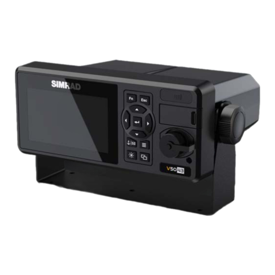
- Page 1 V5043 Class A AIS Transceiver Installation manual English Scan here Scan here www.navico-commercial.com to save a copy to save a copy...
- Page 2 Visit www.navico.com/intellectual-property to review the global trademark rights and accreditations for Navico Group and other entities. • Navico is a trademark of Navico Group. ® • Simrad is a trademark of Kongsberg Maritime AS, licensed to Navico Group. ® • NMEA , NMEA 0183 and NMEA 2000 are trademarks of the National Marine Electronics Association.
- Page 3 RF exposure safe distance The Simrad V5043 Class A AIS Transceiver has been tested and meets applicable limits for radio frequency (RF) exposure. This device ® generates and radiates RF electromagnetic energy and requires a Maximum Permissible Exposure of 1.9 m from the antenna during operation.
-
Page 4: Table Of Contents
8 Equipment in the box 9 Installation procedure 9 RF cable requirements 10 GPS antenna installation 10 VHF antenna installation 12 Mounting the V5043 transceiver main unit 15 Mounting the junction box 16 Junction box connectors 19 Connecting the transceiver to the junction box 20 Connecting to power supply 20 Connecting the optional pilot plug 21 Password... -
Page 5: What Is Ais
WHAT IS AIS? The Automatic Identification System (AIS) is a Very High Frequency (VHF) radio broadcasting system that transfers packets of data over the VHF data link (VDL) and enables AIS equipped vessels and shore- based stations to exchange identification information and navigational data. Ships with AIS transceivers continually transmit their ID, position, course, speed and other data to all nearby ships and shore stations. -
Page 6: V5043 System Overview
It is an excellent choice for SOLAS vessels, commercial ships, professional vessels, and non-SOLAS applications. The V5043 can be connected to the ship’s sensors as required by the IALA guidelines through junction box. The device can also interface external navigation and presentation systems that support IEC 61162-1 related sentences. -
Page 7: Interconnection Diagram
Interconnection diagram GPS antenna VHF antenna V5043 for AIS for AIS Ethernet Pilot plug V5043 NMEA 2000 ® NMEA 0183 ®... -
Page 8: Installation
INSTALLATION Equipment in the box The standard package includes the following items. Please contact your local representative if an item is missing. Parts list Part number Class A AIS transceiver unit 000-16280-001 Junction box 000-12324-001 GPS antenna with 10 m cable 000-12326-001 8-pin Ethernet cable (RJ45 female) Gimbal mounting kit... -
Page 9: Installation Procedure
Mount the transceiver unit to a desired location. Mount junction box. Install VHF antenna (not included with the V5043). Install GPS antenna. Connect all external sensors and data interfaces to the junction box. Connect all required cables to the main transceiver unit. -
Page 10: Gps Antenna Installation
GPS antenna installation A GPS (GNSS) antenna and cable is supplied with the V5043. • Install the GPS antenna in a position where it has a clear view of the sky. The aim is to see 360° around the horizon, with a clear vertical view from 5° above the horizon to 90° above the horizon. - Page 11 Example GPS and VHF antenna locations The diagram below gives an example of the GPS and VHF antennas’ locations on a vessel. Existing equipment or structures on a vessel may require the antennas to be positioned differently. In all cases, for correct operation of the AIS, ensure the positions chosen for the GPS antenna and VHF antenna adhere to the guidelines in the sections GPS antenna installation and VHF antenna installation on page 10.
-
Page 12: Mounting The V5043 Transceiver Main Unit
Mounting the V5043 transceiver main unit Use the following guidelines to check the installation location for your AIS transceiver: • The AIS transceiver should be mounted in a location that is accessible and readable to user at all time. •... - Page 13 Panel mounting Line up the mounting template on control panel to sketch an outline for the cutting area. Using a jigsaw, carefully cut along the sketched cutting area. If necessary, clean up edge with glass paper or file. Mount the transceiver through the opening. Behind the panel, attach a mounting bracket to each side of the unit using the M3X6 screws.
- Page 14 External connectors (transceiver main unit) ETHERNET POWER DATA Name Description Type Power input connector Round type, 3 pins POWER DATA Connect to junction box/ D-Sub 37 pins Connect to sensor or data ports ETHERNET 10Base-T/100Base-TX Round type, 8 pins GPS antenna connector TNC (female) VHF antenna connector SO-239 (female)
-
Page 15: Mounting The Junction Box
Mounting the junction box... -
Page 16: Junction Box Connectors
Junction box connectors Baud rate support: 115200, 57600, 38400, 19200, 14400, 9600, 4800. Junction box external connectors Function Termination switches The switches provide line termination configuration. Termination off Termination on Jumper for NMEA 2000 shield and ground The jumper’s purpose is to wire together ®... - Page 17 Junction box connectors NOTE: A suitable wire gauge (single wire) for junction box connectors is AWG 26–16. See image of ¼ connector below. PILOT_IN BLUE_SIGN SEN2_IN DGPS_IN LR_IN DISP_IN SEN3_IN GND A GND A GND A GND A GND A GND A LR_OUT PILOT_OUT...
- Page 18 Connector Label name Description Function DGPS input Ground DGPS sensor DGPS_IN A DGPS input A DGPS_IN B DGPS input B DGPS output Ground DGPS sensor DGPS_ OUT A DGPS output A DGPS_ OUT B DGPS output B LR input Ground Long range input LR_IN A LR input A...
-
Page 19: Connecting The Transceiver To The Junction Box
Connecting the transceiver to the junction box Use the 37-pin-extension cable (1.8 m) provided in the package to connect the V5043 to the junction box. Note: The end of the extension cable with the EMI ferrite core should be connected at the V5043 main ¼... -
Page 20: Connecting To Power Supply
Connecting to power supply The V5043 requires a 12 V or 24 V DC power supply capable of supplying 4 A peak current. The red wire and the black wire on the 3-pin cable are used to connect the power supply’s positive and negative terminals. -
Page 21: Password
Password Certain information stored in the transceiver can only be changed with the password. The password is required to access the following chapters: • Own ship: contains information about MMSI, vessel name, IMO, call sign and dimension. • Long range settings − •... -
Page 22: Product Specifications
PRODUCT SPECIFICATIONS Applicable standards IEC 61993-2 Ed.3.0, 2018 IMO Resolution A.694(17) IEC 61108-1 Ed.2.0, 2003 IMO Resolution MSC.74(69) Annex 3 IEC 60945 Ed.4.0, 2002 incl. Corr. 1, 2008 IMO Resolution MSC.191(79) IEC 61162-1 Ed.5.0, 2016 IMO Resolution MSC.302(87) IEC 61162-2 Ed.1.0, 1998 ITU-R M.1371-5 (Class A), 2014 IEC 61162-450 Ed.2.0, 2018 IEC 62288 Ed.3.0, 2021... - Page 23 DSC receiver Frequency 156.525 MHz Modulation Channel bandwidth Sensitivity < −112 dBm @ BER < 10 Spurious response rejection ≥ 70 dB for signal @ −104 dBm; BER ≤ 1 % Blocking ≥ 84 dB for signal @ −104 dBm; BER ≤ 1 % GPS (GNSS) receiver (internal) Receiver type 72-channel;...
- Page 24 Keypad 11 keys with backlight Function, escape, voyage/SRM, menu, screen brightness, display, enter, 4 arrow keys Connection interface V5043 main unit front panel Mini type-B USB interface card slot MicroSD type ® ® Pilot plug 206486-2 V5043 main unit rear panel...
- Page 25 Environmental Operating conditions IEC 60945 “protected” category Operating temperature −25°C to +55°C Operating humidity 93% RH at 40°C Waterproof IP54 Physical Width 238 mm (9.37″) Height 135 mm (5.32″) Depth (including connectors) 192.6 mm (7.58″) Weight (main unit) 1.25 kg Pilot Plug (optional) Cable length Connector type...
-
Page 26: Mechanical Dimensions
MECHANICAL DIMENSIONS Transceiver main unit Front (width: 238.14 mm, 9.37 in) 238.14 mm 213.64 mm Side (height: 135 mm, 5.32 in) 94 mm 135 mm... - Page 27 Back (width: 238 mm, 9.37 in) 238.14 mm 213.64 mm Bottom (depth: 192.6 mm, 7.58 in) 38 mm 179.14 mm 187 mm 192.6 mm 163 mm...
-
Page 28: Junction Box
Junction box Extension cable Ethernet cable... -
Page 29: Mounting Template (V5043, Not To Scale)
Mounting template (V5043, not to scale) GPS antenna... -
Page 30: Pilot Plug (Optional)
Pilot plug (optional) -
Page 31: Troubleshooting
TROUBLESHOOTING Use the following guide to perform simple troubleshooting in case the transceiver does not function as it is expected. Due to the complexity of the operation environment of marine electronics, we recommend minimizing sources of interference before proceeding with the troubleshooting by: •... -
Page 32: Troubleshooting Alarm Messages
Troubleshooting alarm messages The V5043 is monitoring itself constantly for failures or other important parameters with the built-in integrity test (BIIT). If abnormal operation is detected in one or more of the following conditions, an alert will be triggered and displayed on the screen, and the transceiver will react as described in the following table. - Page 33 Description text BIIT ID Reaction of the system (transceiver) AIS: internal/external GNSS position mismatch Continue operation This alarm is active if the difference between the internal and external GNSS position is more than 100 m for more than 1 hour. AIS: NavStatus incorrect Continue operation For example, if the navigational status is set to “At...
-
Page 34: Appendix A: Data Interface Technical Information
APPENDIX A: DATA INTERFACE TECHNICAL INFORMATION AIS interface overview... -
Page 35: Data Interface (Iec 61162-2)
Data interface (IEC 61162-2) The V5043 Class A AIS transceiver provides two types of IEC 61162-2 data interface for user applications. The first type of interface includes three input-only sensor data ports, and the second type of interface includes four bidirectional input/output ports. - Page 36 Bidirectional data ports The schematic for a bidirectional data port is shown below (Schematic of a bidirectional data port). The schematic includes an isolated full duplex RS-485 transceiver IC which is used as the main component to handle both data input and output from external data source. The transceiver IC is isolated from external input.
-
Page 37: Supported Data Sentences (Iec 61162)
Supported data sentences (IEC 61162) Data Port Input Sentences Output Sentences Sensor 1 DTM, GBS, GGA, GLL, GNS, GSA, Sensor 2 GSV, HDT, RMC, ROT, THS, VBW, Sensor 3 VHW, VTG DGPS External display pilot ABM, ACA, ACN, ACK, AIQ, AIR, ABK, ACA, ACS, ALC, ALF, ALR, BBM, EPV, LRF, LRI, SSA, SSD, ARC, LR1, LR2, LR3, LRF, NAK,... - Page 38 ACA – AIS Channel assignment message An AIS device can receive regional channel management information. $--ACA,x,llll.ll,a,yyyyy.yy,a,llll.ll,a,yyyyy.yy,a,x,xxxx,x,xxxx,x,x,x,a,x,hhmmss.ss*hh<CR><LF> Field No. Format Description Remark Sequence Number llll.ll,a Region northeast corner latitude – N/S yyyyy.yy,a Region northeast corner longitude – E/W llll.ll,a Region southwest corner latitude – N/S yyyyy.yy,a Region southwest corner longitude –...
- Page 39 AIR – AIS interrogation request This sentence supports ITU-R M.1371 messages 15 and 10. It provides an external application with the means to initiate requests for specific ITU-R M.1371 messages from AIS unit. $--AIR,xxxxxxxxx,x.x,x,x.x,x,xxxxxxxxx,x.x,x*hh<CR><LF> Field No. Format Description Remark xxxxxxxxx MMSI of interrogated station 1 ITU-R M.1371 message requested from station-1...
- Page 40 DTM – Datum reference Local geodetic datum and datum offsets from a reference datum. $--DTM,ccc,a,x.x,a,x.x,a, x.x,ccc*hh<CR><LF> Field No. Format Description Remark Local datum Local datum subdivision code ignored x.x, a Lat offset, min, N/S ignored x.x, a Lon offset, min, E/W ignored Altitude offset, m ignored...
- Page 41 GGA – Global positioning system (GPS) fix data Time, position and fix-related data for a GPS receiver. $--GGA, hhmmss.ss, llll.ll, a, yyyyy.yy, a, x, xx, x.x, x.x, M, x.x, M, x.x, xxxx*hh<CR><LF> Field No. Format Description Remark hhmmss.ss UTC of position llll.ll,a Latitude N/S yyyyy.yy,a...
- Page 42 GNS – GNSS fix data Fix data for single or combined satellite navigation systems (GNSS). This sentence provides fix data for GPS, GLONASS, possible future satellite systems and systems combining these. $-- GNS, hhmmss.ss, llll.ll, a, yyyyy.yy, a, c--c,xx,x.x,x.x,x.x,x.x,x.x,a *hh<CR><LF> Field No.
- Page 43 HDT – Heading true Actual vessel heading in degrees true produced by any device or system producing true heading. $--HDT, x.x, T*hh<CR><LF> Field No. Format Description Remark x.x, T Heading, degrees true LRF – AIS long-range function This sentence is used in both long-range interrogation requests and long-range interrogation replies. The LRF-sentence is the second sentence of the long-range interrogation request pair, LRI and LRF (see the LRI-sentence).
- Page 44 RMC – Recommended minimum specific GNSS data Time, date, position, course and speed data provided by a GNSS navigation receiver. $--RMC, hhmmss.ss, A, llll.ll,a, yyyyy.yy, a, x.x, x.x, xxxxxx, x.x,a, a, a*hh<CR><LF> Field No. Format Description Remark hhmmss.ss UTC of position fix Status llll.ll,a Latitude, N/S...
- Page 45 SSA –Sender signature authentication This sentence can be used both for authentication of sender and for authentication of untampered content. For this purpose, the sentence has to be applied before the protected sentence (for example EPV, SSD). Other sentences shall not be interleaved between the sender signature authentication sentence and protected sentence, and the time between the SSA and the protected sentence should be limited.
- Page 46 THS – True heading and status Actual vessel heading in degrees true produced by any device or system producing true heading. This sentence includes a “mode indicator” field providing critical safety related information about the heading data, and replaces the deprecated HDT sentence. $--THS,x.x,a*hh<CR><LF>...
- Page 47 VSD – AIS voyage static data This sentence is used to enter information about a ship’s transit that remains relatively static during the voyage. $--VSD,x.x,x.x,x.x,c--c,hhmmss.ss,xx,xx,x.x,x.x*hh<CR><LF> Field No. Format Description Remark Type of ship and cargo category Maximum present static draught Persons on-board c--c Destination...
- Page 48 PAMC, DBG – proprietary sentences, debug The proprietary sentences are additional sentences only applicable to this product. Its main usage is for enabling testing mode and parameter settings. This sentence is used for configuration. It commands unit with given parameters. $PAMC,C,c-c,x,x,x,x,x,x,x,x*hh<CR><LF>...
-
Page 49: Interpretation Of Output Sentences
PAMC, DSC – Proprietary sentences, digital selective calling When AIS transceiver receives DCS messages, this sentence is used to output DSC pattern. $PAMC,R,DSC,c-c*hh<CR><LF> Field No. Format Description Remark DSC pattern ACN – Alert command This sentence is used for acknowledge, silence, responsibility transfer and to request repeat of alert details in case the reception process has detected, based on ALC, that ALF has been missed. - Page 50 ACA – AIS channel assignment message An AIS device can receive regional channel management information. $-ACA,x,llll.ll,a,yyyyy.yy,a,llll.ll,a,yyyyy.yy,a,x,xxxx,x,xxxx,x,x,x,a,x,hhmmss.ss*hh<CR><LF> Field No. Format Description Remark Sequence number llll.ll,a Region northeast corner latitude – N/S yyyyy.yy,a Region northeast corner longitude – E/W llll.ll,a Region southwest corner latitude –...
- Page 51 ALR – Set alarm state Local alarm condition and status. This sentence is used to report an alarm condition on a device and its current state of acknowledgment. $--ALR,hhmmss.ss,xxx,A, A,c--c*hh<CR><LF> Field No. Format Description Remark hhmmss.ss Time of alarm condition change, Unique alarm number (identifier) at alarm source Alarm condition,...
- Page 52 LR1 – AIS long-range reply sentence 1 The LR1 sentence identifies the destination for the reply and contains the information items requested by the “A” function identification character (see the LRF sentence). $--LR1,x,xxxxxxxxx,xxxxxxxxx,c--c,c--c,xxxxxxxxx*hh<CR><LF> Field No. Format Description Remark Sequence number xxxxxxxxx MMSI of responder xxxxxxxxx...
- Page 53 LR3 – AIS long-range reply sentence 3 The LR3 sentence contains the information items requested by the “I, O, P, U and W” function identification character (see the LRF sentence). $--LR3,x,xxxxxxxxx,c--c,xxxxxx,hhmmss.ss,x.x,x.x,x.x,x.x,x.x,x.x*hh<CR><LF> Field No. Format Description Remark Sequence number xxxxxxxxx MMSI of responder c--c Voyage destination, 1 to 20 characters...
- Page 54 TRL –AIS transmitter-non-functioning log This sentence is specific to AIS class A stations. It is intended to support the retrieval of the AIS non- functioning log information. $--TRL,x.x,x.x,x,xxxxxxxx,hhmmss.ss,xxxxxxxx,hhmmss.ss,x*hh<CR><LF> Field No. Format Description Remark Total number of log entries Log entry number Sequential message identifier xxxxxxxx Switch off date...
- Page 55 VDM – AIS VHF data-link message This sentence is used to transfer the entire contents of a received AIS message packet, as defined in ITU-R M.1371 and as received on the VHF Data Link (VDL), using the “six-bit” field type. !--VDM,x,x,x,a,s--s,x*hh<CR><LF>...
- Page 56 ALC – Cyclic alert list The purpose of this sentence is to satisfy the needs for safe and consistent data distribution with minimal data traffic. Each change on an alert’s data leads to an incremented revision counter, so an alert- processing device needs only check the alert entries in the ALC messages to ensure that no ALF message has been lost.
- Page 57 ALF – Alert sentence This sentence is used to report an alert condition and the alert state of a device. An ALF message shall be published for an alert each time the alert information in this sentence changes and on alert request. $--ALF,x,x,x,hhmmss.ss,a,a,a,aaa,x.x,x.x,x.x,x,c---c*hh <CR><LF>...
-
Page 58: Appendix B: Nmea 2000 ® Pgn Information
APPENDIX B: NMEA 2000 PGN INFORMATION ® The following table is a list of the NMEA 2000 PGNs supported by the V5043 unit. ® Output Description 59392 ISO Acknowledgment 59904 ISO Request 60160 ISO Transport Protocol, Data Transfer 60416 ISO Transport Protocol, Connection Management... - Page 59 129809 AIS Class B “CS” Static Data Report, Part A 129810 AIS Class B “CS” Static Data Report, Part B 129811 AIS Single Slot Binary Message 129812 AIS Multi Slot Binary Message 129813 AIS Long-Range Broadcast Message 129816 AIS Acknowledge 129793 AIS UTC and Date Report 129794...
- Page 60 Input Description 59392 ISO Acknowledgment 59904 ISO Request 60160 ISO Transport Protocol, Data Transfer 60416 ISO Transport Protocol, Connection Management 60928 ISO Address Claim 65240 ISO Commanded Address 126208 NMEA – Request group function ® NMEA – Command group function ®...
-
Page 61: Appendix C: Installation And Maintenance Record
APPENDIX C: INSTALLATION AND MAINTENANCE RECORD The following installation information should be completed and retained on board the vessel for maintenance records. Installation and maintenance record Vessel information Vessel name Flag state IMO number MMSI number Owner/Company Radio call sign Type of vessel Gross tonnage Length (m) -
Page 62: Gps (Gnss) Antenna Location
GPS (GNSS) antenna location GPS (GNSS) antenna location A: distance to bow (m) B: distance to stern (m) C: distance to port-side (m) D: distance to starboard (m) Connected sensors and devices Connected sensors and devices Connected port Equipment Model number Sensor 1 Sensor 2 Sensor 3... -
Page 63: Installer Information
Installer information Installer information Connected port Equipment Model number Company name Technician’s name Telephone/Mobile no. Address Place Date Installer’s Signature... - Page 64 ©2024 Navico Group. All Rights Reserved. Navico Group is a division of Brunswick Corporation. ®Reg. U.S. Pat. & Tm. Off, and ™ common law marks. Visit www.navico.com/intellectual-property to review the global trademark www.navico-commercial.com rights and accreditations for Navico Group and other entities.
Need help?
Do you have a question about the V5043 and is the answer not in the manual?
Questions and answers