
Subscribe to Our Youtube Channel
Related Manuals for Grundig GCI-K0512W


Summary of Contents for Grundig GCI-K0512W
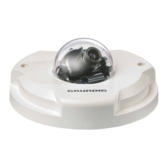
- Page 1 Owner´s Manual IP Cameras & Domes GCI-K0512W 1080P Full HD Flat Fixed Dome IP Camera GCI-K0512W.14.1.01.02.2011 © ASP AG...
-
Page 3: Table Of Contents
14. View User Information 1. Introduction Following the high standards of GRUNDIG IP Cameras, this IP Camera is capable of serving real-time streaming and makes the images run smoothly (25 images/second). In addition to MJPEG real time streaming, this IP Camera develops a superior H.264 main profile codec to smoothly transfer High Definition surveillance data through the Internet without distortion. -
Page 4: Important Safety Instructions
If this product fails to operate normally, contact the nearest service center. Never disassemble or modify this product in any way. (GRUNDIG is not liable for problems caused by unauthorized modifications or attempted repair.) To prevent fire or electric shock, do not expose the inside of this device to rain or moisture. -
Page 5: Camera Overview
4.1. Camera Overview 4.2. System Requirements To perform the IP Camera via web browser, please ensure your PC is in good network connection, and meets the system requirements as described below. Personal Computer : 1.) Intel Pentium M, 2.16 GHz or Intel Core 2 Duo, 2.0 GHz 2.) 2 GB RAM or more Operating System : Windows XP / Windows VISTA / Windows 7... -
Page 6: Ethernet Connection
4.3. Ethernet Connection For waterproofing the RJ-45 Dongle please us a corresponding Screw-On Plug (not included in the package). Please refer to the instructions for the Screw-on Plug to waterproof the connection correctly. English... -
Page 7: Deleting The Existing Grundig Viewer
5. Deleting the Existing GRUNDIG Viewer For users who have installed the GRUNDIG Viewer for 1.3 Megapixel Series IP Cameras on the PC, please first delete the existing GRUNDIG Viewer from the PC before accessing this IP Camera. Deleting the GRUNDIG Viewer : Click “Control Panel”, and then click on “Add or Remove Programs”. -
Page 8: Accessing The Camera
6. Accessing the Camera For initial access to the IP Camera, users can search the camera through the installer program: GRUNDIG Finder.exe, which can be found on the supplied CD. GRUNDIG Finder Software Setup : Step 1: Double-click on the program GRUNDIG Finder.exe (see the icon below);... - Page 9 Step 2: The security alert window will pop up. Click “Unblock” to continue. Device Search : Step 3: Click “Find Device” again, and all the IP devices found will be listed on the page, as shown in the picture below. The IP Camera’s default IP address is: 192.168.1.1. English...
- Page 10 Step 4: Double-click or right-click and select “Browse” to access the camera directly via web browser. Step 5: Then the dialogue box for entering the default username and password (as shown below) will appear for logging in to the IP Dome Camera. The default login ID and password for the Administrator are: Login ID: admin Password: 1234...
- Page 11 Step 1: In the finding device list, click on the IP Camera of which you would like to change the network property. On the selected item, right-click and select “Network Setup”. Meanwhile, record the IP Camera’s MAC address, for future identification. Step 2: The “Network Setup”...
- Page 12 Installing the GRUNDIG Viewer Software Online : For initial access to the IP Camera, a client program, GRUNDIG Viewer, will be automatically installed to your PC when connected to the IP Camera. If the Web browser doesn’t allow the GRUNDIG Viewer installation, please check the Internet security settings or ActiveX controls and plug-ins settings (see 14.
- Page 13 Image and Focus Adjustment : The image appears on the Home page when successfully accessing to the IP Camera. Adjust zoom and focus as necessary to produce a clear image. Step 1: Unscrew the IP Dome Camera’s cover. Step 2: Loosen the tilt fixed screw and adjust the camera´s tilt angle; loosen the focus fixed screw, and rotate the lens counter-/clockwise to adjust the focus.
-
Page 14: Browser-Based Viewer Introduction
7. Browser-based Viewer Introduction The picture below shows the Home page of the IP Camera’s viewer window. There are five tabs on the left (Home, System, Streaming, Camera and Logout) and one tab on the right (Languages). Home : Users can monitor the live video of the targeted area. System setting : The administrator can set host name, system time, admin password, network related settings, etc. -
Page 15: Home Page
8. Home Page In the Home page, there are several function buttons right down the displayed image. NOTE: Please note that the function buttons will vary depending on the camera model. Display Mode (Screen Size Adjustment) : Image display size can be adjusted to x1/2 and full screen. Digital Zoom Control : In the full screen mode, users can implement digital PTZ by rotating the mouse wheel (for zoom in/out), and drag the mouse into any direction. - Page 16 NOTE: Users with Windows 7 operating system need to follow the following procedure to be able to use the Snapshot function. First you need to log on to your computer as an Administrator. Then you go to Windows Start menu, click with the right mouse button on your Internet Browser and select in the appearing pop-up window “Run as Administrator”.
-
Page 17: System Related Settings
9. System Related Settings The picture below shows all categories under the “System” tab. Each category in the left column will be explained in the following sections. NOTE: The “System” configuration page is only accessible by the Administrator. 9.1. Host Name & System Time Setting Press the first category: <System>... -
Page 18: Security
Host Name : The name is for camera identification (max. 30 characters). If alarm function is enabled and is set to send an alarm message by Mail/FTP, the host name entered here will display in the alarm message. Time Zone : Select the time zone you are in from the drop-down menu. - Page 19 Admin Password : Change the administrator’s password by putting in the new password in both text boxes. The input characters/numbers will be displayed as dots for security purposes. After clicking <Save>, the web browser will ask the Administrator for the new password for access. The maximum length of the password is 14 digits. NOTE: The following characters are valid: A-Z, a-z, 0-9, !#$%&’-.@^_~.
- Page 20 Manage User : To delete a user, pull down the user list, and select the user name you wish to delete. Then click <Delete> to remove it. To edit a user, pull down the user list and select a user name. Click <Edit> to edit the user’s password and privilege.
- Page 21 <HTTPS> : <HTTPS> allows secure connections between the IP Camera and the web browser using the <Secure Socket Layer (SSL)> or the <Transport Layer Security (TLS)>, which prevent camera settings or Username/Password info from snooping. It is required to install a self-signed certificate or a CA-signed certificate for implementing <HTTPS>.
- Page 22 Create Self-signed Certificate : Before a CA-issued certificate is obtained, users can create and install a self-signed certificate first. Click the <Create> button under “Create self-signed certificate” and provide the requested information to install a self-signed certificate for the IP Camera. Please refer to the last part of this section: Provide the Certificate Information for more details.
- Page 23 Create Certificate Request : Click the “Create Certificate Request” button to create and submit a certificate request in order to obtain a signed certificate from CA. Provide the requested information in the Create Dialog. Please refer to the following Provide the Certificate Information for more details.
- Page 24 When the signed certificate is returned, install it by uploading the signed certificate. Provide the Certificate Information : To create a Self-signed HTTPS Certificate or a Certificate Request to CA, please enter the information as requested: English...
- Page 25 - Country: Enter a 2-letter combination code to indicate the country the certificate will be used in. For instance, type in “GB” to indicate Great Britain. - State or province: Enter the local administrative region. - Locality: Enter other geographical information. - Organisation: Enter the name of the organisation to which the entity identified in “Common Name”...
- Page 26 <IP Filter> : When using the IP filter, access to the IP Camera can be restricted by denying/allowing specific IP addresses. General : - Enable IP Filter: Check the box to enable the IP Filter function. Once enabled, the listed IP addresses (IPv4) will be allowed/denied access to the IP Camera.
- Page 27 <IEEE 802.1X> : The IP Camera is allowed to access a network protected by 802.1X/EAPOL (Extensible Authentication Protocol over LAN). Users need to contact the network administrator to receive certificates, user IDs and passwords. CA Certificate : The CA certificate is created by the Certification Authority for the purpose of validating itself. Upload the certificate for checking the server’s identity.
-
Page 28: Network
9.3. Network Click the category: <Network>, there will be a drop-down menu with tabs including <Basic>, <QoS>, <SNMP>, and <UPnP>. <Basic> : Users can choose to connect to the IP Camera through a fixed or dynamic (DHCP) IP address. The IP Camera also provides PPPoE (Point-to-Point Protocol over Ethernet) support for users who connect to the network via PPPoE. - Page 29 192.168.7.254. Press “Save” to confirm the new setting. When using a static IP address to login to the IP Camera, users can access it either through the “GRUNDIG Finder” software (see 6. Accessing the Camera) or input the IP address in the URL bar and press “Enter”.
- Page 30 - Secondary DNS: Secondary DNS is a secondary domain name server that backups the primary DNS. Use PPPoE : For the PPPoE users, enter the PPPoE Username and Password into the fields, and click on the “Save” button to complete the setting. Advanced : - Web Server port: The default web server port is 80.
- Page 31 <QoS> (Quality of Service) : QoS allows providing differentiated service levels for different types of traffic packets, which guarantees delivery of priority services especially when network congestion occurs. Adapting the Differentiated Services (DiffServ) model, traffic flows are classified and marked with DSCP (DiffServ Codepoint) values, and thus receive the corresponding forwarding treatment from DiffServ capable routers.
- Page 32 <SNMP> (Simple Network Management Protocol) : With Simple Network Management Protocol (SNMP) support, the IP Camera can be monitored and managed remotely by the network management system. SNMP v1/v2 : - Enable SNMP: Select the version of SNMP to use by checking the box. - Read Community: Specify the community name which has read-only access to all supported SNMP objects.
- Page 33 <UPnP> : UPnP Setting : - Enable UPnP: When the UPnP is enabled, whenever the IP Camera is presented to the LAN, the icon of the connected IP Cameras will appear in My Network Places to allow for direct access as shown below. NOTE: To enable this function, please make sure the UPnP component is installed on your computer.
-
Page 34: Ddns
- Enable UPnP port forwarding: When the UPnP port forwarding is enabled, the IP Camera is allowed to open the web server port on the router automatically. NOTE: To enable this function, please make sure that your router supports UPnP and is activated. - Friendly name: Set the name for the IP Camera for identity. -
Page 35: Mail
9.5. Mail The Administrator can send an e-mail via Simple Mail Transfer Protocol (SMTP) when a motion is detected. SMTP is a protocol for sending e-mail messages between servers. SMTP is a relatively simple, text-based protocol, where one or more recipients of a message are specified and to whom the message text is transferred. The configuration page is shown below: Two sets of SMTP can be configured. -
Page 36: Ftp
9.6. FTP The Administrator can set to sending alarm messages to a specific File Transfer Protocol (FTP) site when motion is detected. Users can assign an alarm message to up to two FTP sites. The FTP setting page is shown below. Enter the FTP details, which include server, server port, user name, password and remote folder, in the fields. -
Page 37: Http
9.7. HTTP A HTTP Notification server can listen for notification messages from IP Cameras by triggered events. The HTTP setting page is shown below. Enter the HTTP details, which include server, user name, and password in the fields. <Alarm> triggered and <Motion Detection> notifications can be sent to the specified <HTTP> server. Click “Save”... -
Page 38: Motion Detection
9.8. Motion Detection The Motion Detection function allows detecting suspicious motion and triggering alarms when motion volume in the detected area reaches/exceeds the determined sensitivity threshold value. In the Motion Detection setting page is a frame (Motion Detection Window) displayed in the Live View Pane. The Motion Detection Window is for defining the motion detection area. - Page 39 When motion is detected, the signals will be displayed in the Motion window as shown below: Detailed settings of Motion Detection are described as follows: Motion Detection : You will be able to turn on/off Motion Detection in the System section: Motion Detection. The default setting is Off. Motion Detection Setting : Users can adjust various parameters of Motion Detection in this section.
- Page 40 - Upload Image by FTP: Select this item, and the Administrator can assign a FTP site and configure various parameters as shown in the picture below. When a motion is detected, event images will be uploaded to the appointed FTP site. - Upload Image by E-Mail: Select this item, and the Administrator can assign an e-mail address and configure various parameters as shown in the picture below.
-
Page 41: Tampering
9.9. Tampering The Tampering Alarm function helps the IP Camera against tampering such as deliberate redirection, blocking, spray paint, and lens covering, etc. through video analysis and reaction to such events by sending out notifications or uploading snapshots to the specified destination(s). Detection of camera tampering is achieved by measuring the differences between the older frames of video (which are stored in buffers) and more recent frames. -
Page 42: Storage Management
- Upload Image by FTP: Select this item, and the Administrator can assign a FTP site and configure various parameters as shown in the figure below. When tampering is detected, event images will be uploaded to the appointed FTP site. NOTE: The capital letter A/M/R appearing in the very beginning of a name denotes the sort of the recording: A stands for Alarm;... - Page 43 NOTE: Please format the Micro SD/SDHC card when using it for the first time. Formatting will also be required when a memory card has already been used on one camera and was later transferred to another camera with a different software platform. Device Information : When users insert the Micro SD/SDHC card, the card information such as the memory capacity and status will be shown in the Device Information section.
- Page 44 When the recording mode is set to “Always” (consecutive recording) in the submenu "Recording" and the Micro SD/SDHC card recording is also allowed to be enabled when triggered by events, once the events occur, the system will immediately implement the recorded events to the memory card. After events recording, the IP Camera will return to regular recording mode.
-
Page 45: Recording
9.11. Recording In the Recording setting page, users can specify the recording schedule that fits the present surveillance requirement. Activating Micro SD/SDHC Card Recording : Two types of schedule mode are offered: "Always" and "Only during time frame". Users can setup the time frame to fit the recording schedule or choose “Always”... -
Page 46: File Location
9.12. File Location Users can specify a storage location for the snapshots and the live video recording. The default setting is: C:\. Once the setting is confirmed, press “Save,” and all the snapshots and recordings will be saved in the designate location. -
Page 47: View Log File
9.13. View Log File Click on the link to view the system log file. The content of this file provides useful information about configuration and connections after system boot-up. English... -
Page 48: View User Information
9.14. View User Information The Administrator can view each user’s login information and their privileges (see section 9.2. Security). View User Login Information : All the users in the network will be listed in the “User Information” zone, as shown below. The picture below shows: User: 4321 This indicates that one user’s login username is: User, and the password is: 4321 English... - Page 49 View User Privilege : If you press “Get user privacy” at the bottom of the page, the Administrator will be able to view each user’s privileges. As the picture above shows: User: 1:1:0:1 1:1:0:1 = I/O access : Camera control : Talk : Listen (see 9.2. Security) This denotes that the user has been granted the privileges of I/O access, Camera control and Listen.
-
Page 50: View Parameters
9.15. View Parameters Click on this item to view the entire system’s parameter setting. 9.16. Factory Default The factory default setting page is shown below. Follow the instructions to reset the IP Camera to factory default setting if needed. English... -
Page 51: Software Version
Set Default : Click on the “Set Default” button to recall the factory default settings. Then the system will restart in 30 seconds. NOTE: The IP address will be restored to default. Reboot : Click on the “Reboot” button, and the system will restart without changing the current settings. 9.17. -
Page 52: Software Upgrade
Step 4: Close the video browser. Step 5: Click “Control Panel”, and then double-click on “Add or Remove Programs.” In the “Currently installed programs” list, select “GRUNDIG Viewer” and click the button “Remove” to uninstall the existing GRUNDIG Viewer. Step 6: Open a new web browser, re-login the IP Camera, and then allow the automatic download of the GRUNDIG Viewer. -
Page 53: Maintenance
9.19. Maintenance Users can export configuration files to a specified location and retrieve data by uploading an existing configuration file to the IP Camera. Export: Users can save the system settings by exporting the configuration file (.bin) to a specified location for future use. Press the “Export”... -
Page 54: Streaming Settings
10. Streaming Settings Press the tab ”Streaming” on the top of the page, and the configurable video and audio items will display in the left column. In Streaming, the Administrator can configure specific video resolution, video compression mode, video protocol, audio transmission mode, etc. Further details of these settings will be specified in the following sections. - Page 55 Text Overlay Settings : Users can select the items to display data including date/time/text on the live video pane. The maximum length of the string is 18 alphanumeric characters. Click “Save” to confirm the Text Overlay setting. Video Rotation Type : Users can change the video display type if necessary.
-
Page 56: Video Compression
10.2. Video Compression Users can specify the values for MJPEG/H.264 compression mode in the video compression page (see the picture below), depending on the application. MJPEG Compression Settings (MJPEG Q (Quality) factor): A higher value implies higher bit rates and a higher visual quality. The default setting is 35; the setting range is from 1 to 70. - Page 57 CBR Mode Setting : The CBR (Constant Bit Rate) mode can become the preferred bit rate mode if the bandwidth available is limited. It is important to take into account the image quality when you choose to use CBR mode. Click “Save”...
-
Page 58: Video Ocx Protocol
10.3. Video OCX Protocol In the Video OCX protocol setting page, users can select RTP over UDP, RTP over TCP, RTSP over HTTP or MJPEG over HTTP, for streaming media over the network. In the case of multicast networking, users can select the Multicast mode. -
Page 59: Video Frame Rate
10.4. Video Frame Rate The Frame rate options include: - 25 fps - 12.5 fps - 5 fps - 2.5 fps - 1.5 fps Click "Save" to confirm the setting. English... -
Page 60: Video Mask
10.5. Video Mask There are up to five video masks which can be set by the users. Active Mask Function : - Add a Mask: Check a Video Mask checkbox, and a red frame will come out in the Live Video pane at the right side. Use the mouse to drag and drop in order to adjust the mask’s size and place it on the target zone. -
Page 61: Audio
10.6. Audio The audio setting page is shown below. In the Audio page, the Administrator can select one transmission mode and audio bit rate. - Simplex (Listen only): In the Listen only Simplex mode, the local/remote site can only listen to the other site. - Disable: Select the item to turn off the audio transmission function. -
Page 62: Camera Settings
11. Camera Settings The picture below is the camera configuration page. Details of each parameter setting are described in the following subsections. NOTE: Camera settings and function buttons may vary depending on the camera model. 11.1. Exposure Setting The Exposure pull-down menu is as follows: The exposure is the amount of light received by the image sensor and is determined by the width of lens diaphragm opening, the amount of exposure by the sensor (shutter speed) and other exposure parameters. -
Page 63: White Balance Setting
NOTE: The minimum shutter speed will vary depending on the setting in Full Auto Mode. Fixed Shutter Mode : In this mode, a fixed shutter speed can be selected from the drop-down menu. The shutter speed range is from 1/10000 to 1/1.5 sec. with 18 options. Users can choose a suitable shutter speed according to the environmental illumination. -
Page 64: Sharpness Setting
11.4. Sharpness Setting Sharpness Setting Increasing the sharpness level can make the image look sharper; it especially enhances the object’s edges. Press < √ > to confirm the new setting. 11.5. Contrast Setting The camera image contrast level is adjustable; please choose from a range of -6 to +19. Press <... -
Page 65: Logout
12. Logout Press the tab “Logout” at the top of the page, and the login window will pop up. This permits login with another user name. English... -
Page 66: Cms Software Introduction
13. CMS Software Introduction The Central Management System (CMS) software bundles the IP cameras into one system. Offering powerful functionalities via intuitive interface, it is a centralized monitoring solution for your video surveillance equipments. It gives the user access to monitor multiple IP Cameras, and allows the user to simultaneously monitor 16 sites per group (up to 10 groups) within several clicks. - Page 67 Step 3: Click the <Security> tab, and select <Internet>. Step 4: Down the page, press “Default Level” (see the picture above) and click “OK” to confirm the setting. Close the browser window, and open a new one later when accessing the IP Camera. ActiveX Controls and Plug-in Settings : Step 1~3: Refer to the previous section above.
- Page 68 The Security Settings screen is displayed as shown below: Step 5: Under “ActiveX controls and plug-ins”, set ALL items (as listed below) to <Enable> or <Prompt>. Please note that the items may vary depending on the Internet Explorer version you are using. ActiveX controls and plug-in settings: 1.
-
Page 69: Grundig Viewer Download Procedure
The procedure of GRUNDIG Viewer software download is specified as follows: Step 1: In the GRUNDIG Viewer installation page, click “Next” for starting the installation. Step 2: Setup starts. Please wait for a while until the loading bar runs out. - Page 70 Step 3: Click “Finish” to close the GRUNDIG Viewer installation page. Then, the IP Camera’s Home page will display as follows: NOTE: Please note that the function buttons may vary depending on the camera model. English...
-
Page 71: Install Upnp Components
16. Install UPnP Components Please follow the instructions below to install UPnP components. (The procedure is for Windows XP, for other systems please refer to the corresponding manuals.) Step 1: Go to “Start”, click on “Control Panel”, and then double-click on “Add or Remove Programs”. Step 2: Click on “Add/Remove Windows Components”... - Page 72 Step 3: Select “Networking Services” from the Components list in the Windows Components Wizard window, and then click “Details”. Step 4: Select “UPnP User Interface” in the Networking Services’ subcomponents list and then click “OK”. Step 5: Click “Next” in the Windows Components Wizard page. English...
- Page 73 Step 6: Click “Finish” to complete the installation. English...
- Page 74 Specifications GCI-K0512W Image Sensor 1/2.7" CMOS Omnivision, 2 megapixel Pixels - total 1920(H) x 1080(V), Full HD Sensitivity 0.1 lux @ F1.6 Lens Focal Length 4 mm Viewing Angle 78° Motion Detection On/ Off/ Sensitivity/ Area setting Privacy zones 2 zones, rectangle...
Need help?
Do you have a question about the GCI-K0512W and is the answer not in the manual?
Questions and answers