Table of Contents
Advertisement
Advertisement
Table of Contents

Subscribe to Our Youtube Channel
Related Manuals for Grundig Reason GCI-K2795P-1


Summary of Contents for Grundig Reason GCI-K2795P-1
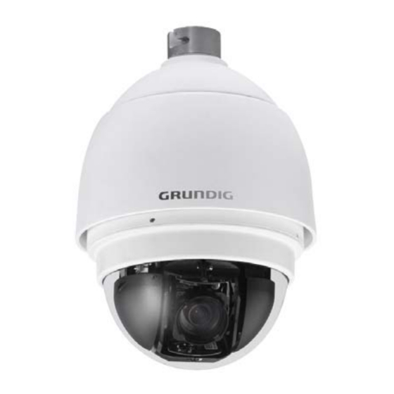
- Page 1 Owner's Manual IP Cameras GCI-K2795P 2 MP Full HD Outdoor Motorized Dome IP-Camera 30x Zoom ICR WDR GCI-K2795P-1 2 MP Full HD Outdoor Motorized Dome IP-Camera 30x Zoom ICR WDR GCI-F0795P 3 MP Full HD Outdoor Motorized Dome IP-Camera 30x Zoom GCI-K2795P.146.3.14.04.2016 ©...
-
Page 3: Table Of Contents
14. Internet Security Settings 11. Periodical Event 15. GRUNDIG Viewer Download Procedure 12. Autotracking 16. Install UPnP Components 13. Storage Management (on Camera) 17. Deleting the Existing GRUNDIG Viewer 14. Recording (on Camera) 15. Schedule 16. File Location (on PC) English... -
Page 4: Important Safety Instructions
If this product fails to operate normally, contact the nearest service center. Never disassemble or modify this product in any way. (GRUNDIG is not liable for problems caused by unauthorised modifications or attempted repair.) To prevent fire or electric shock, do not expose the inside of this device to rain or moisture. -
Page 5: Installation
4. Installation Do not install the product in a location subject to high temperature (over 50°C), low temperature (below -10°C), or high humidity. Doing so may cause fire or electric shock. Keep out of direct sunlight and heat radiation sources. This may cause fire. Avoid aiming the camera directly towards extremely bright objects such as the sun, as this may damage the image sensor. -
Page 6: Cable Connection
Web Browser : Microsoft Internet Explorer 6.0 or later Firefox Chrome Safari Network Card : 10Base-T (10 Mbps) or 100Base-TX (100 Mbps) operation Viewer : ActiveX control plug-in for Microsoft IE 4.4. Cable Connection For operation, the Motordome IP Camera requires a power cable and a cable with a RJ-45 connector as described below. -
Page 7: Alarm Connection
4.5. Alarm Connection The Motordome Camera supports 4 digital alarm inputs and 2 digital alarm outputs. Please make sure the alarm connections are properly wired before you start to configure the alarm related settings on the “Application” menu page. Please refer to the pin definition table below for alarm system wiring. NOTE: This pin definition table indicates the status of the alarm I/O after the camera is powered up. -
Page 8: Accessing The Camera
Finder.exe, which can be found on the supplied CD. GRUNDIG Finder Software Setup : Step 1: Double-click on the program GRUNDIG Finder.exe (see the desktop icon below). Its window will appear as shown below. Then click on the “Find Device” button. - Page 9 Step 4: Double-click or right-click and select “Browse” to access the camera directly via the web browser. Step 5: Then the dialogue box for entering the default user name and password (as shown below) will appear for login to the IP Dome Camera. The default login ID and password for the Administrator are: Login ID: admin Password: 1234...
- Page 10 Step 1: In the finding device list, click on the IP Camera of which you would like to change the network property. Right-click on the selected item, and select “Network Setup”. Meanwhile, record the IP Camera’s MAC address for future identification. Step 2: The “Network Setup”...
- Page 11 15. GRUNDIG Viewer Download Procedure. NOTE: If the Live Video Pane on the Home Page cannot be shown to the users who have installed the GRUNDIG Viewer on the PC previously, please refer to the procedure in chapter 17. Delete the Existing GRUNDIG Viewer.
-
Page 12: Video Resolution Setup
6. Video Resolution Setup The users can set up the Video Resolution on the Video Format page of the user-friendly browser-based configuration interface. The page “Video Format” can be found in the IP camera menu under the path: Streaming > Video Format. Under the Video Resolution section in the menu page “Video Format”, please select your preferred resolution setting. - Page 13 English...
- Page 14 Click on “Save” to confirm the setting. English...
-
Page 15: Browser-Based Viewer Introduction
7. Browser-based Viewer Introduction The picture below shows the Home page of the IP Camera’s viewer window. There are four tabs on the left (System, Streaming, PTZ and Logout) and one tab on the right (Languages). System setting : The administrator can set host name, system time, admin password, network related settings, etc. Further details will be interpreted in chapter 9. -
Page 16: Home Page
8. Home Page In the Home page, there are several function buttons that are specified below. NOTE: Please note that the function buttons can vary depending on the camera model. Display Mode (Screen Size Adjustment) : The display size of the image can be adjusted to x1/2 and full screen. Talk Button (on/off) : Talk function allows the local site to talk to the remote site. - Page 17 Recording button (on/off) : When you click on this button, the recordings from the Live View will be saved to the location specified in the “File Location” page. The default storage location for the recording is: C:/. See section 9.16. 'File Location (on PC)' for further details.
- Page 18 - Manual Focus: After clicking on the “Manual” button, users can adjust the focus manually via the “Near” and “Far” buttons. The status will also be displayed above the screen as shown below. Multiple Languages Support : Multiple languages are supported for the viewer window interface. English...
- Page 19 Furthermore, after clicking on the <Control Panel> Button, the Control Panel will be shown as in the figure below. Control Panel : - Pan & Tilt Direction Control: The <Pan and Tilt Direction Control> on the Control Panel allows users to control the Camera with browser viewers other than IE.
-
Page 20: System Related Settings
9. System Related Settings The picture below shows all categories under the “System” tab. Each category in the left column will be explained in the following sections. NOTE: The “System” configuration page is only accessible by the Administrator. 9.1. Host Name & System Time Setting Click on the first category <System>... -
Page 21: Security
Host Name : The name is for camera identification (max. 30 characters). If the alarm function (see section 9.8. 'Application (Alarm Settings)') is enabled and is set to send an alarm message by Mail/FTP, the host name entered here will be displayed in the alarm message. - Page 22 NOTE: The following characters are valid: A-Z, a-z, 0-9, !#$%&’-.@^_~. Admin Password : Change the administrator’s password by putting in the new password in the “Admin password” and “Confirm password” text boxes. The input characters/numbers will be displayed as dots for security purposes. After clicking <Save>, the web browser will ask the Administrator for the new password for access.
- Page 23 <HTTPS> : <HTTPS> allows secure connections between the IP Camera and the web browser using the <Secure Socket Layer (SSL)> or the <Transport Layer Security (TLS)>, which prevent others from snooping on your camera settings or Username/Password. It is required to install a self-signed certificate or a CA-signed certificate for implemention of <HTTPS>.
- Page 24 Create self-signed certificate : Before a CA-issued certificate is obtained, users can create and install a self-signed certificate first. Click on the <Create> button under “Create self-signed certificate” and provide the requested information to install a self-signed certificate for the IP Camera. Please refer to the last part of this section: "Provide the Certificate Information"...
- Page 25 Install signed certificate : Click on the “Create Certificate Request” button to create and submit a certificate request in order to obtain a signed certificate from the CA (Certificate Authority). Provide the requested information in the Create Dialog. Please refer to the section "Provide the Certificate Information"...
- Page 26 When the signed certificate is returned, install it by uploading the signed certificate. Provide the Certificate Information : To create a Self-signed HTTPS Certificate or a Certificate Request to CA, please enter the information as requested: English...
- Page 27 - Country: Enter a 2-letter combination code to indicate the country the certificate will be used in. For instance, type in “GB” to indicate Great Britain. - State or province: Enter the local administrative region. - Locality: Enter other geographical information. - Organisation: Enter the name of the organisation to which the entity identified in “Common Name”...
- Page 28 <IP Filter> : When using the IP filter, access to the IP Camera can be restricted by denying/allowing specific IP addresses. General : - Enable IP Filter: Check the box to enable the IP Filter function. Once enabled, access to the IP Camera will be allowed/denied for the listed IP addresses (IPv4).
- Page 29 <IEEE 802.1X> : The IP Camera can access a network protected by 802.1X/EAPOL (Extensible Authentication Protocol over LAN). To do this, users need to contact the network administrator to receive certificates, user IDs and passwords. CA Certificate : The CA certificate is created by the Certification Authority for the purpose of validating itself. Upload the certificate for checking the server’s identity.
-
Page 30: Network
9.3. Network When you click on the category <Network>, there will be a drop-down menu with several tabs including <Basic>, <QoS>, <SNMP>, and <UPnP>. <Basic> : Users can choose to connect to the IP Camera through a fixed or dynamic (DHCP) IP address. The IP Camera also provides PPPoE (Point-to-Point Protocol over Ethernet) support for users who connect to the network via PPPoE. - Page 31 192.168.44.1. Click on “Save” to confirm the new setting. When using a static IP address to login to the IP Camera, users can access it either through the “GRUNDIG Finder” software (see 6. Accessing the Camera) or input the IP address in the URL bar and click on “Enter”.
- Page 32 - Secondary DNS: Secondary DNS is a secondary domain name server that backs up the primary DNS. Use PPPoE : The PPPoE users need to enter the PPPoE Username and Password into the fields, and need to click on the “Save”...
- Page 33 DSCP Settings : The DSCP value range is from 0 to 63. The default DSCP value is 0, which means that DSCP is disabled. The IP Camera uses the following QoS Classes: Video, Audio and Management. - Video DSCP: This class consists of applications such as MJPEG over HTTP, RTP/RTSP and RTSP/HTTP. - Audio DSCP: This setting is only available for the IP Cameras which support audio.
- Page 34 Traps for SNMP v1/v2 : Traps are used by the IP Camera to send messages to a management system about important events or status changes. - Enable Traps: Check the box to activate trap reporting. - Trap address: Enter the IP address of the management server. - Trap community: Enter the community to use when sending a trap message to the management system.
- Page 35 UPnP Setting : - Enable UPnP: When UPnP is enabled, whenever the IP Camera is presented to LAN, the icon of the connected IP Cameras will appear in My Network Places to allow for direct access as shown below. NOTE: To enable this function, please make sure the UPnP component is installed on your computer. Please refer to chapter 16.
-
Page 36: Ddns
9.4. DDNS The Dynamic Domain Name System (DDNS) allows a host name to be constantly synchronised with a dynamic IP address. In other words, it allows those using a dynamic IP address to be associated to a static domain name so that others can connect to it through this name. -
Page 37: Mail
9.5. Mail The Administrator can can set up the sending of an e-mail via Simple Mail Transfer Protocol (SMTP) when an event is triggered. SMTP is a protocol for sending e-mail messages from server to server. SMTP is a relatively simple, text-based protocol, where one or more recipients of a message are specified and to whom the message text is transferred. -
Page 38: Ftp
9.6. FTP The Administrator can set the sending of alarm messages to a specific File Transfer Protocol (FTP) site when an event is detected. Users can assign an alarm message to up to two FTP sites. The FTP setting page is shown below. -
Page 39: Http
9.7. HTTP A HTTP Notification server can listen for notification messages from IP Cameras by triggered events. The HTTP setting page is shown below. Enter the HTTP details, which include the server name (for instance, http://192.168.1.1/admin.php), user name, and password into the fields. <Alarm> triggered and <Motion Detection>... - Page 40 Alarm Status Settings : The specific alarm pin’s property can be programmed in this section as shown below. Alarm Switch : The Administrator can enable or disable the alarm function. Alarm Type : Select an alarm type, “Normal close” or “Normal open”, that corresponds with the alarm application. Alarm Output : Define the alarm output signal as “high”...
- Page 41 - Upload Image by FTP: After selecting this item, the Administrator can assign a FTP site and configure various parameters as shown in the picture below. When a motion is detected, event images will be uploaded to the appointed FTP site. The <Pre-trigger buffer>...
- Page 42 - Upload Image by E-Mail: After selecting this item, the Administrator can assign an e-mail address and configure various parameters as shown in the figure below. When the alarm is triggered, event images will be sent to the appointed e-mail address.
- Page 43 If the selected function is “Preset”, it is required to enter its dwell time (1 ~ 256 sec.) in the corresponding field as shown below. When the alarm is triggered, the camera will go to the selected Preset Point and stay there for a user-defined period of time.
- Page 44 - Send HTTP notification: Check this item, select the destination HTTP address, and specify the parameters for event notifications when <Motion Detection> is triggered. When an alarm is triggered, the notification can be sent to the specified HTTP server. For instance, if the custom parameter is set as ”action=1&group=2”, and the HTTP server’s name is” http://192.168.1.200/admin.php”, the notification will be sent to the HTTP server as ”http://192.168.1.200/admin.php? Action=1&group=2”...
-
Page 45: Motion Detection
- Add sequence number suffix (no maximum value): File name: imageXXXXXXX.jpg X: Sequence Number - Add sequence number suffix up to _ and then start over: File Name: imageXX.jpg X: Sequence Number The file name suffix will end at the number being set. For example, if the setting is “10”, the file name will start from 00, end at 10, and then start all over again. - Page 46 If the Motion Detection function is activated, a pop-up window (Motion) with motion indication will be shown. When a motion is detected, the signals will be displayed in the Motion window as shown below: The detailed settings of Motion Detection are described as follows: Motion Detection : You will be able to turn the Motion Detection on/off in the System section "Motion Detection".
- Page 47 - Send Message by E-Mail: The Administrator can choose to send an alarm message by E-Mail when a motion is detected. - Upload Image by FTP: After selecting this item, the Administrator can assign a FTP site and configure various parameters as shown in the figure below.
- Page 48 NOTE: Make sure SMTP or FTP configuration has been completed. See section 9.5. Mail and 9.6. FTP for further details. - Send HTTP notification: Check this item, select the destination HTTP address, and specify the parameters for event notifications when an <Alarm>...
-
Page 49: Network Failure Detection
9.10. Network Failure Detection The Network Failure Detection function allows the IP Camera to ping another IP device (e.g. NVR, VSS, Video Server, etc.) within the network periodically and generates some actions in case of network failure occurance, for instance, when a Video Server is somehow disconnected. Being capable of implementing local recording (through Micro SD card) when a network failure happens, the IP Camera can be a backup recording device for the surveillance system. -
Page 50: Periodical Event
Select <Upload for __ sec> to set the recording duration after the alarm is triggered. The setting range is from 1 to 99999 seconds. Select <Upload while trigger is active> to record the triggered video until the trigger is turned off. NOTE: Please make sure the local recording (with Micro SD/ SDHC card) is activated so that this function can be implemented. -
Page 51: Autotracking
9.12. Autotracking The Autotracking function is only for the models GCI-K0779P and GCI-K1779P. This function will only become available after authentication is done. For more information about authenticating the function, please see the Insert Key section below. The Autotracking function will automatically detect a moving object in the preset area and follow it according to the defined settings. - Page 52 - Enable tilt limit: Tick the box to enable the tilt limit setting. - Get U Tilt / D Tilt: Please click and drag the PTZ pointer in the view window to the desired up or down tilt position. Then click on the <Get U Tilt>...
- Page 53 - Off / On: The default setting of Home Setting is <Off>. Select <On> to enable the function. - Home Position: To set the home position, please click and drag the PTZ pointer in the view window to the desired position. Click on <Set>...
-
Page 54: Storage Management (On Camera)
<Insert Key> : If the Autotracking function is already available, users do not need to type in any product key in this page. However, if it is not, please contact the system installers or the sales representatives for the product key. Authentication can be done by typing in the product key in the blank space provided in the Insert Key page and by clicking on <OK>... - Page 55 NOTE: Please format the Micro SD/SDHC card when using it for the first time. Formatting will also be required when a memory card has already been used on one device and was later transferred to another device with a different software platform. Device Information : When users insert the Micro SD/SDHC card, the card information such as the memory capacity and status will be shown in the Device Information section.
- Page 56 When the recording mode is set to “Always” (consecutive recording) in the submenu "Recording" and the Micro SD/SDHC card recording is also allowed to be enabled when triggered by events, once the events occur, the system will immediately implement the recorded events to the memory card. After event recording, the device will return to regular recording mode.
-
Page 57: Recording (On Camera)
9.14. Recording (on Camera) In the Recording setting page, the Micro SD Card recording schedule supports up to ten sets of time frames. Users can specify the recording schedule to fit their present surveillance requirements. Activating Micro SD/SDHC Card Recording : Two types of schedule mode are offered: "Always"... - Page 58 Setting a schedule: To set a schedule, please select a time frame from the time frame list first. Then check the boxes at the bottom of the time frame to choose the specific weekdays. At last, type in the start time (hour:minute) and the duration time (hour:minute) for activation of the schedule triggered features.
-
Page 59: File Location (On Pc)
9.16. File Location (on PC) Users can specify a storage location for the snapshots and the live video recording. The default setting is: C:\. Once the setting is confirmed, click on “Save,” and all the snapshots and recordings will be saved in the designated location. -
Page 60: View Information
9.17. View Information <Log File>: Click on the link to view the system log file. The content of this file provides useful information about configuration and connections after system boot-up. English... - Page 61 <User Information>: The Administrator can view each user’s login information and their privileges (see section 9.2. Security). View User Login Information : All the users in the network will be listed in the “User Information” zone, as shown below. The picture below shows: User: 4321 This indicates that one user’s login username is: User, and the password is: 4321 English...
- Page 62 View User Privilege : If you click on “Get user privacy” at the bottom of the page, the Administrator will be able to view each user’s privileges. As the picture above shows: User: 1:1:0:1 1:1:0:1 = I/O access : Camera control : Talk : Listen (see 9.2. Security) This denotes that the user has been granted the privileges of I/O access, Camera control and Listen.
-
Page 63: Factory Default
<Parameters>: Click on this item to view the entire system’s parameter setting. 9.18. Factory Default The factory default setting page is shown below. Follow the instructions to reset the IP Camera to factory default setting if needed. English... -
Page 64: Software Version
Full Restore : Click on the “Full Restore” button to recall the factory default settings. After 30 seconds the system will restart. Partial Restore : Click on the “Partial Restore” button to recall the factory default settings, except for the network settings. NOTE: The IP address will also be restored to default (192.168.1.1). -
Page 65: Software Upgrade
Step 5: Go to “Start” on your Windows desktop, activate “Control Panel”, and then double-click on ”Add or Remove Programs“. In the “Currently installed programs” list, select “GRUNDIG Viewer” and click on the button “Remove” to uninstall the existing GRUNDIG Viewer. -
Page 66: Maintenance
9.21. Maintenance Users can export configuration files to a specified location and retrieve data by uploading an existing configuration file to the IP Camera. This is especially convenient if you want to have the same configuration for multiple cameras. Export: Users can save the system settings by exporting the configuration file (.bin) to a specified location for future use. -
Page 67: Streaming Settings
10. Streaming Settings 10.1. Video Format Video Resolution : Under the Video Resolution section, the available video resolution formats include MJPEG and H.264. Please refer to Chapter 6. Video Resolution Setup for combination details. Click on “Save” to confirm the setting. Text Overlay Settings : Users can select these items to display data (date/time/text) on the live video pane. - Page 68 To rotate the image, users can select “Flip video”, for instance. Then the displayed image will be reversed as shown below. The following are descriptions of different video rotation types. - Flip video: If you select <Flip video>, the image will be rotated horizontally. - Mirror video: If you select <Mirror video>, the image will be rotated vertically.
-
Page 69: Video Compression
10.2. Video Compression Users can specify the values for MJPEG/H.264 compression mode in the video compression page (see the picture below), depending on the application. MJPEG compression setting (MJPEG Q (Quality) factor): A higher value implies higher bit rates and a higher visual quality. The default setting is 35; the setting range is from 1 to 70. -
Page 70: Video Ocx Protocol
10.3. Video OCX Protocol In the Video OCX protocol setting page, users can select RTP over UDP, RTP over TCP, RTSP over HTTP or MJPEG over HTTP, for streaming media over the network. In the case of multicast networking, users can select the Multicast mode. -
Page 71: Video Frame Rate
10.4. Video Frame Rate Video frame skipping is for saving bandwidth if necessary. The setting page is shown below. MJPEG / H.264-1 / H.264-2 / H.264-3 / H.264-4 Frame Rate: The default setting of MJPEG/H.264-1/H.264-2/H.264-3/H.264-4 Frame Rate is 25 fps. The setting range is from 1 to 25. -
Page 72: Audio (Audio And Bit Rate Settings)
10.5. Audio (Audio and Bit Rate Settings) The audio setting page is shown below. In the Audio page, the Administrator can select one transmission mode and the audio bit rate. Transmission Mode : - Full-duplex (Talk and Listen simultaneously): In the Full-duplex mode, the local and remote sites can communicate with each other simultaneously, i.e. both sites can speak and be heard at the same time. -
Page 73: Ptz Settings
11. PTZ Settings Under the “PTZ” category, users are allowed to program Preset Point(s), Cruise Line(s), Auto Pan Path(s) and Sequence Line(s) via PTZ controls. Additionally, various camera settings including Auto Exposure (AE), White Balance (WB), Back Light Compensation (BLC), Sharpness, Exposure Compensation, Digital Zoom, etc. can also be set here. -
Page 74: Cruise
11.2. Cruise The Motordome Camera supports up to eight Cruise Paths. Please follow the instructions below for the setup of a Cruise Path. Cruise Setting : To set up a Cruise Path, please first select a path number from the drop-down list. Then move the cursor to the live view pane, and move the camera to a desired view (via PTZ controls) as the start point of a Cruise Path. -
Page 75: Auto Pan
11.3. Auto Pan The Motordome Camera supports four Auto Pan Paths. Please refer to the instructions below to set an Auto Pan Path. Auto Pan Setting : To set up an Auto Pan Path, please select first a path number from the drop-down list. Then move the cursor to the live view pane, and move the camera to a desired view as the Start Point of an Auto Pan Path. -
Page 76: Sequence
11.4. Sequence The Motordome Camera supports in total eight Sequence Lines. Each Sequence Line consists of up to 64 Preset Points. Please refer to the instructions below to program a Sequence Line. NOTE: Before setting this function, users must pre-define at least two Preset Points. Sequence Setting : Please press the “Edit”... -
Page 77: Home
- Sequence Line: Please select the number of Sequence Lines to be set from the drop-down list on the top of the Sequence setting menu. - Sequential Preset Points Setting: Please set up each Preset Point of the programmed Sequence Line in order, by assigning a Preset Point from the “Name”... -
Page 78: Tilt Range
- Time: The time here represents the duration of camera idle time previous to running a Preset Point/Cruise Line/Auto Pan Path/Sequence Line. When the Home function is activated, the Dome Camera will start to count down when it idles, and then execute the predefined action as time expires. The time period ranges from 1 to 128 minutes; please specify it in the field. -
Page 79: Privacy Mask
11.7. Privacy Mask The Privacy Mask function aims to avoid any intrusive monitoring. When setting a mask, it is suggested to set it at least twice bigger (height and width) than the masked object. The Dome Camera will assume that the center of the selected view is the starting point. -
Page 80: Camera - Exposure
Mask Clearing : In this section, users can delete an existing Privacy Mask. Please select the Privacy Mask to be removed from the drop-down list, and click on the button “Clear”. Then the selected Privacy Mask will readily disappear. 11.8. Camera - Exposure In the Exposure setting page, users can select either the “Full Auto”... -
Page 81: Camera - Wb
11.9. Camera - WB To display natural colours, the camera needs to know the reference colour temperature of the light source. Based on this reference colour temperature the camera will calculate the correct values for all colours. The camera can perform a measurement by itself or the user can set up the reference colour temperature manually. The scale unit of the colour temperature is Kelvin [K]. -
Page 82: Camera - Misc
11.10. Camera - Misc 1 In Camera—Misc (Miscellaneous Setups) 1, users can set various camera parameters including Backlight Compensation (BLC), Sharpness, Exposure Compensation (ExpComp), Image Flip, Digital Zoom and the ICR function. Each setting is specified as follows: BLC : Users can choose to activate or disable the BLC function. - Page 83 NOTE: The Privacy Mask function will be automatically disabled when the Image Flip function is enabled. Speed by Zoom : Enable this function to adjust the pan/tilt speed automatically by an internal algorithm when zooming. A larger zoom ratio leads to a lower rotation speed. Click on the <Set> button to save the setting. ICR Function : When you detach the IR cut filter from the image sensor and turn off the colour burst function, you will get a black-and-white picture.
-
Page 84: Camera - Default
2DNR : With the 2D Noise Reduction function, the processor analyses pixel by pixel and frame by frame to eliminate environmental noise signals so that the highest image quality can be produced, even in low light conditions. Press the “Set” button when the setting is finished. TV System : Select the video format that matches the present TV system. -
Page 85: Logout
The GRUNDIG CMS Software gives the user access to monitor multiple IP Cameras and Video Servers, and allows the user to monitor simultaneously 16 sites per group (up to 10 groups) within several clicks. -
Page 86: Internet Security Settings
14. Internet Security Settings If the ActiveX control installation is blocked, please either set the Internet security level to default or change ActiveX controls and plug-in settings. Internet Security Level : Default Step 1: Start the Internet Explorer. Step 2: Select <Tools> from the main menu of the browser. Then click on <Internet Options>. Step 3: Click on the <Security>... - Page 87 Step 4: Down the page, click on “Default level…” and then click “OK” to confirm the setting. Close the browser window, and open a new one later when accessing the IP Camera. ActiveX Controls and Plug-in Settings : Step 1~3: Please refer to the previous section above. Step 4: Down the page, click on “Custom level…”...
- Page 88 The Security Settings screen is displayed as shown below: Step 5: Under “ActiveX controls and plug-ins”, set ALL items (as listed below) to <Enable> or <Prompt>. Please note that the items may vary depending on the Internet Explorer version you are using. ActiveX controls and plug-in settings: 1.
-
Page 89: Grundig Viewer Download Procedure
The procedure of the GRUNDIG Viewer software download is specified as follows: Step 1: In the GRUNDIG Viewer installation page, click “Next” to start the installation. Step 2: Setup starts. Please wait for a while until the loading bar runs out. - Page 90 Step 3: Click on “Finish” to close the GRUNDIG Viewer installation page. Then, the IP Camera’s Home page will be displayed as follows: NOTE: Please note that the function buttons may vary depending on the camera model. English...
-
Page 91: Install Upnp Components
16. Install UPnP Components Please follow the instructions below to install UPnP components. (The procedure is for Windows XP, for other systems please refer to the corresponding manuals.) Step 1: Go to “Start”, click on “Control Panel”, and then double-click on “Add or Remove Programs”. Step 2: Click on “Add/Remove Windows Components”... - Page 92 Step 3: Select “Networking Services” from the Components list in the Windows Components Wizard window, and then click on “Details”. Step 4: Select “UPnP User Interface” in the Networking Services’ subcomponents list and then click on “OK”. Step 5: Click on “Next” in the Windows Components Wizard page. English...
-
Page 93: Deleting The Existing Grundig Viewer
Step 6: Click on “Finish” to complete the installation. 17. Deleting the Existing GRUNDIG Viewer Users who have installed the GRUNDIG Viewer for 1.3 Megapixel Series IP Cameras on the PC need to delete the existing GRUNDIG Viewer first from the PC before accessing this IP Camera. - Page 94 STEP 1: Click on the “Tools” tab and select the option “Internet Options”. STEP 2: Click on “Delete” in the first pop-up window. Then tap “Delete Files” in the “Temporary Internet files” section in the next pop-up window. English...
- Page 95 Specifications GCI-K2795P Image Sensor 1/2.8" CMOS Progressive Scan Sony Exmor™ Pixels - Total 1920(H) x 1080(V) Sensitivity Colour 0.5 lux @ F1.6 (IRE50) / 0.2 lux @ F1.6 (IRE30) Sensitivity B&W 0.095 lux @ F1.6 (IRE50) / 0.06 lux @ F1.6 (IRE30) Col/B&W On/Off/Auto, IR-cut filter removable (ICR) Lens Focal Length...
- Page 96 Access protection By log-in and Password, IP filter, IEEE802.1x Number of Clients Up to 20 user, 1 x Admin SD memory supports up to 64 GB capacity of micro SD/SDHC/SDXC memory Recording Types: on Micro SD/SDHC/SDXC CARD Single Image Recording (JPEG) Video(AVI, LCK) Web Browser MS Internet Explorer 6.0 (or higher), Firefox, Google Chrome, Safari...
- Page 97 English...
- Page 98 EC Declaration of Conformity GCI-K2795P 2 MP Full HD Outdoor Motorized Dome IP- Camera 30x Zoom ICR WDR GCI-K2795P-1 2 MP Full HD Outdoor Motorized Dome IP- Camera 30x Zoom ICR WDR GCI-F0795P 3 MP Full HD Outdoor Motorized Dome IP- Camera 30x Zoom ICR It is hereby certified that the products meet the standards in the following relevant provisions:...
Need help?
Do you have a question about the Reason GCI-K2795P-1 and is the answer not in the manual?
Questions and answers