
Related Manuals for PACOM PAC-VN70IIS-VFA12


Summary of Contents for PACOM PAC-VN70IIS-VFA12
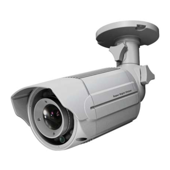
- Page 1 PAC-VN70IIS-VFA12 IR Night Vision Outdoor Camera INSTALLATION MANUAL version 1.0.1...
- Page 2 The lighting flash with an arrowhead symbol, within an equilateral triangle is intended to alert the user to the presence of non‐insulated dangerous voltage within the product’s enclosure that may be of sufficient magnitude to constitute a risk of electric shock to persons. The exclamation point within an equilateral triangle is intended to alert the user to the presence of important operating and maintenance (servicing) instructions in the literature accompanying the appliance. INFORMATION This equipment has been tested and found to comply with limits for a Class A digital device, pursuant to part 15 of the FCC Rules. These limits are designed to provide reasonable protection against harmful interference when the equipment is operated in a commercial environment. This equipment generates, uses, and can radiate radio frequency energy and, if not installed and used in accordance with the instruction manual, may cause harmful ...
-
Page 3: Table Of Contents
Table of content Installation manual Precautions ‐‐‐‐‐‐‐‐‐‐‐‐‐‐‐‐‐‐‐‐‐‐‐‐‐‐‐‐‐‐‐‐‐‐‐‐‐‐‐‐‐‐‐‐‐‐‐‐‐‐‐‐‐‐‐‐‐‐‐‐‐‐‐‐‐‐‐‐‐‐‐‐‐‐‐‐‐4 1. 2. Limitation of liability ‐‐‐‐‐‐‐‐‐‐‐‐‐‐‐‐‐‐‐‐‐‐‐‐‐‐‐‐‐‐‐‐‐‐‐‐‐‐‐‐‐‐‐‐‐‐‐‐‐‐‐‐‐‐‐‐‐‐‐‐‐‐‐‐‐5 3. Disclaimer of warranty ‐‐‐‐‐‐‐‐‐‐‐‐‐‐‐‐‐‐‐‐‐‐‐‐‐‐‐‐‐‐‐‐‐‐‐‐‐‐‐‐‐‐‐‐‐‐‐‐‐‐‐‐‐‐‐‐‐‐‐‐‐‐5 4. Package ‐‐‐‐‐‐‐‐‐‐‐‐‐‐‐‐‐‐‐‐‐‐‐‐‐‐‐‐‐‐‐‐‐‐‐‐‐‐‐‐‐‐‐‐‐‐‐‐‐‐‐‐‐‐‐‐‐‐‐‐‐‐‐‐‐‐‐‐‐‐‐‐‐‐‐‐‐‐‐‐‐‐‐6 5. Special features of the model ‐‐‐‐‐‐‐‐‐‐‐‐‐‐‐‐‐‐‐‐‐‐‐‐‐‐‐‐‐‐‐‐‐‐‐‐‐‐‐‐‐‐‐‐‐‐‐‐‐‐‐‐‐7 6. Installation ‐‐‐‐‐‐‐‐‐‐‐‐‐‐‐‐‐‐‐‐‐‐‐‐‐‐‐‐‐‐‐‐‐‐‐‐‐‐‐‐‐‐‐‐‐‐‐‐‐‐‐‐‐‐‐‐‐‐‐‐‐‐‐‐‐‐‐‐‐‐‐‐‐‐‐‐‐‐‐‐8~11 7. Troubleshooting ‐‐‐‐‐‐‐‐‐‐‐‐‐‐‐‐‐‐‐‐‐‐‐‐‐‐‐‐‐‐‐‐‐‐‐‐‐‐‐‐‐‐‐‐‐‐‐‐‐‐‐‐‐‐‐‐‐‐‐‐‐‐‐‐‐‐‐‐‐‐‐12~13 8. Dimension (mm) ‐‐‐‐‐‐‐‐‐‐‐‐‐‐‐‐‐‐‐‐‐‐‐‐‐‐‐‐‐‐‐‐‐‐‐‐‐‐‐‐‐‐‐‐‐‐‐‐‐‐‐‐‐‐‐‐‐‐‐‐‐‐‐‐‐‐‐‐‐‐‐13 9. Specification ‐‐‐‐‐‐‐‐‐‐‐‐‐‐‐‐‐‐‐‐‐‐‐‐‐‐‐‐‐‐‐‐‐‐‐‐‐‐‐‐‐‐‐‐‐‐‐‐‐‐‐‐‐‐‐‐‐‐‐‐‐‐‐‐‐‐‐‐‐‐‐‐‐‐‐‐‐14 ... -
Page 4: Precautions
1. Precautions Please read the manual carefully before the installation in order to set up the camera correctly and to obtain the best picture quality. Please keep the manual in good condition for your future reference and service application. Installation and services should be only carried out by an authorized personnel according to local safety regulations. If any liquid or solid matter gets into the housing, immediately disconnect the camera from power supply and have it checked by your authorized dealer before reusing.. Avoid installing the camera in extremely hot or cold places. If you are not a certified person, never try to dismantle the camera. To avoid electric shock, never remove the screws or covers. There are no parts inside that need maintenance by the user. All maintenance should be carried out by qualified personnel. Avoid installing the camera at a place of high humidity. Avoid installing the camera at the place exposed to gas or oil. Keep the top glass of the lens always clean in order to obtain the best picture quality all the time. Be careful not to be stained by fingerprint. Don't face the camera directly toward sunlight or sunlight reflecting area. CCD may go defective at this condition. Please give a special attention to keep the unit from dangerous drop or external shock during the process of transportation or handling. Never try to touch the camera in wet hand. It may cause an electric shock. Do not expose the camera to radioactivity. It causes a serious damage on the CCD. ... -
Page 5: Limitation Of Liability
2. Limitation of liability This publication is provided “AS IS” without warranty of any kind, either express or implied, including but not limited to, the implied warranties of merchantability, fitness for any particular purpose, or non‐infringement of the third party's right. This publication could include technical inaccuracies or typographical errors. Changes are added to the information herein, at any time, for the improvements of this publication and/or the corresponding product(s). 3. Disclaimer of warranty In no event shall seller be liable to any party or any person, except for replacement or reasonable maintenance of the product, for the cases, including but not limited to below: (1) Any damage and loss, including without limitation, direct or indirect, special, consequential or exemplary, arising out of or relating to the product; (2) Personal injury or any damage caused by inappropriate use or negligent operation of the user; (3) Unauthorized disassemble, repair or modification of the product by the user; (4) Inconvenience or any loss arising when images are not displayed, due to any reason or cause including any failure or problem of the product; ... -
Page 6: Package
4. Package Ext‐Video Cable x 1 Camera x 1 Instruction manual x 1 OSD manual x 1 Power + Video Cable x 1 Tapping screws x3 Plastic anchor x 3 ... -
Page 7: Special Features Of The Model
5. Special features of the model 1. Higher resolution of 600TVL(D)/650TVL(N) This unit has come up with an innovative way of increasing cubic resolution to more than 30% higher than that of conventional 600TVL cameras. It upgrades horizontal resolution to 600TVL and vertical resolution to 540TVL so that the cubic resolution becomes 324KTVL while conventional cameras provide only 240KTVL. 2. Unbeatable WDR Performance This unit provides a very unique and far superior image scanning capability of defining the details of differently contrasted areas compared with any other conventional WDR cameras. With current WDR technologies, defining images in shaded areas are typically not clear enough with over‐exposed picture ... -
Page 8: Installation
6. Installation 6‐1. How to mount to Ceiling ① Drill three screw holes on the ceiling plate to fix three anchors (supplied) in the holes. ② Fix the plastic anchors in the holes. ③ Position the mounting bracket on the screw points. ④ Fix the mounting bracket by tightening the screws. ⑤ Slightly loosen bolt (A) then adjust TILT (180°) and rotation (360°) of the camera using a serration on the bracket and tighten the bolt firmly. ⑥ Slightly loosen bolt (B) then adjust pan (360°) of the camera and tighten the bolt firmly version 1.0.1... - Page 9 6‐2. How to install to Wall ① Drill three screw holes on the wall plate to fix three plastic anchors (supplied) in the holes. ② Fix the plastic anchors in the holes. ③ Position the mounting bracket on the screw points. ④ Fix the mounting bracket by tightening the screws. ⑤ Slightly loosen bolt (A) then adjust tilt(180˚) and rotation(360˚) of the camera using a serration on the bracket and tighten the bolt firmly. ⑥ Slightly loosen bolt (B) then adjust pan(360˚) of the camera and tighten the bolt firmly. version 1.0.1...
- Page 10 6‐3. 3‐Axis adjustment ① Pan 360˚ Slightly loosen Pan bolt then adjust pan of the camera using a serration on the bracket and tighten the bolt firmly . ② Tilt 180˚ Slightly loosen Tilt bolt then adjust tilt of the camera using a serration on the bracket and tighten the bolt firmly.
- Page 11 - How to use Connect Extra video output (BNC cable) to LCD monitor as a picture. 6‐6 Waterproof processing of cable end connection Make sure to use a butyl tape. (Do not use a sealing material on those parts) It is useful to connect the cable ends from camera to the extension cable for waterproof. Connect and tape the power cables (Power‐Power/Ground‐Ground). Bind the power cables together with the tape. When DC‐Jack is used, tape the DC‐DC joint. Connect and tape the RS485 cables (RS485+ㅡTRX+ /RS485‐ ㅡTRX‐) Tape the BNC‐BNC joint. version 1.0.1...
- Page 12 7. Troubleshooting If there are problems in operating, please refer to the checklist below. If the problem persists, please contact the agent where this product is purchased. Problems Troubleshooting Nothing appears on the screen. Please check that the power cord and line connection between the camera and monitor are fixed properly. Please check that you have properly connected VIDEO cable to the camera VIDEO output jack. The image on the screen is dim. Is lens stained with dirt? Clean your lens with soft, clean cloth. Set the monitor to proper condition. If the camera is exposed to too strong light, change the camera position. The image on the screen is dark. Adjust the contrast feature of the monitor. If you have an intermediate device, set the 75Ω / Hi‐Z properly (Please check the impedance) The camera is not working Please check that you have properly connected the camera properly, and the surface to an appropriate power source. of the camera is hot. Please check if DAY NIGHT menu is set to ‘AUTO1’. The DAY/NIGHT menu does not work. Please check that AGC of EXPOSURE SETUP menu is set to ‘OFF’. The SENS‐UP function Please check that SHUTTER of EXPOSURE SETUP menu is set to does not work. ‘A.FLK’ or ‘FIXED’. The MOTION DETECTION Please check if MOTION DETECTION function is turned on. function is not working. Please check if MD LEVEL is too low. Please check the setting of the MD area. ...
-
Page 13: Troubleshooting
Problems Troubleshooting RS‐485 Please check the polarity between RS‐485 Control Port communication fails. and RS‐485 cable. 485 Control Board Connection Port RS‐485 Control Port (+)CONNECTION TERMINAL(TRX+) 485+ (‐)CONNECTION TERMINAL(TRX‐) 485‐ Please check if the initial value of the RS‐485 Communication setup matches between camera and OSD Controller or DVR. *RS‐485 Communication establishment initial value Item Camera ID BAUD RATE UART MODE RET PKT Initial value 1 9600 8‐NONE‐1 ENABLE We recommend that you make ground connection between camera and controller for safe communication control. When RS‐485 cable is not properly connected, A warning message ‘ERROR RS‐485 Connection. Please reconnect and Reboot’ is displayed. Then please turn off the power and connect the cable again. 8. Dimension (mm) ... -
Page 14: Specification
9. Specification Class NIGHT VISION CAMAERA Power Source 12VDC/24VAC 100㎃ (IR Off) /400㎃ (IR On) Image CCD 1/3” Sony Super HAD Ⅱ Effective pixels PAL : 752(H) x 582(V) Resolution 600TVL (Day) / 650TVL (Night) Sync Scanning Sys 2 : 1 Interlace Synchronization Internal Frequency PAL : 15.625KHz(H), 50KHz(V) Electrical Min.Illumination 0 Lux / IR On Video Out 1Vp‐p Composite 75 Ohm S/N Ratio More than 52dB(AGC Off) Shutter Speed PAL : 1/50~90,000/sec. Gamma Control Standard : r=0.45 White Balance 1500°K~11,000°K Auto, ATW/Cor‐Roll/Push/Manual Gain Control Standard : ‐6dB~34dB Auto /Maximum by OSD IR LED IR Spectrum 850nm 8Ø x 14ea ... - Page 15 OSD Manual for functions control 1. On Screen Menu (OSD) 2. Setting up the menu 1. Press the Tact SW to enter <MAIN MENU>. 2. Move the arrow to a specific menu by pushing the Tact SW up or down. 3. Adjust the selected feature by pushing the Tact SW left or right How to use OSD button (Tact SW) Press to enter the menu to save settings Push up or down to select functions Push left or right to adjust a level or mode of sub‐menu 4. When completed, move the arrow indicator to ‘EXIT’ and press the Tact SW to finish all settings. version 1.0.1...
- Page 16 Note ∙ If ‘ ‘ indication appears on a selected sub‐menu, press the Tact SW to get into a following menu. ‐‐‐ ∙ If ‘ ‘ indication appears on any sub‐menu, it means the function with this mark is deactivated. (Ex : When SENS‐UP is OFF, 3‐DNR becomes deactivated ‘‐‐‐‘ ) 3. LENS Select the lens and adjust the SETUP suitable to the type of lens. When DC lens is used. ( Default) 1. Please select the lens mode to DC IRIS. 2. Press the Tact SW to enter the <DC IRIS MENU>. ‐ BRIGHTNESS: adjust the brightness of screen when the environment is extremely bright or dark. ‐ REACTION: Reaction speed of the shutter is adjustable. It is useful when the light condition of the environment keeps changing quickly. 3. Save Press SAVE to finish all settings and return to <MAIN MENU> When MANUAL lens is used. 1. Please select the lens mode to MANUAL. 2. Press the Tact SW to enter the <MANUAL IRIS MENU>. ‐ BRIGHTNESS: same as above ‐ REACTION: same as above 4. EXPOSURE (1) AGC (Auto Gain Control) ‐ OFF: Deactivates the AGC function. ‐ LOW: Allows automatic gain control from 0 to 20dB. ( Default) ‐ MIDDLE: Allows automatic gain control from 0 to 30dB. ‐ HIGH: Allows automatic gain control from 0 to 42dB. The higher the gain level, the brighter the screen becomes while the higher the noise as well. (2) SHUTTER ...
- Page 17 Note ∙ When the SHUTTER is set to MANUAL mode, SENS‐UP does not operate. ∙ When the AGC is set to OFF, SENS‐UP does not operate. (4) INITIAL SET Initialize all settings of EXPOSURE menu. (5) SAVE 5. DAY / NIGHT It is used to improve the sensitivity and clarity of picture quality at low light ‐ DAY : The image is always displayed in color. ‐ NIGHT : The image is always displayed in black and white. ‐ AUTO1: The image is automatically converted to B/W from Color at 3 lux. IR WDR LEVEL: Select Anti‐ IR saturation level ‐ OFF/LOW/MIDDL /HIGH ● IR WDR ADJUST: Adjust the value in each of selected level ‐ 0 ~ 6 ● ‐ AUTO2: The image is automatically converted to B/W from Color at 3 lux. ∙ D/N LEVEL: LOW/MIDDLE/HIGH ∙ FILTER DLY: Select the duration time about changing the Day/Night mode. (1 SEC, 3 SEC, 5 SEC, 10 SEC, 15 SEC, 30 SEC, 60 SEC) ∙ NIGHT BURST: Burst ON/OFF selectable. ∙ INITIAL SET: Initialize all settings of AUTO2 menu. Default setting ‐ Infrared camera: AUTO1 ‐ Non‐Infrared camera: AUTO2 6. WDR/BLC/ECLPS The image quality is greatly improved with the use of this mode when there is a strong backlight behind the object. ‐ OFF : Deactivates the WDR function. ‐ WDR: Camera scans both of bright lit background and shaded area distinctively under an extremely contrasted light situation. (LOW/MIDDEL/HIGH) ‐ BLC: Enables a user to directly select a desired area from a picture and ...
- Page 18 ECLIPSE: Can mask the head lights to view car license number plate more clearly. Can select masking color. Adjust the ECLIPS level at the GAIN CONTROL as OFF mode. 7. White Balance (WHITE BAL) This is useful to optimize the white balalnce control under a certain artificial lighting area where a standard white balance condition is not suitable. ‐ (Auto Tracking White Balance) ...
- Page 19 8. 2D‐DNR (2D Noise Reduction) ‐ LOW ‐ MIDDLE ‐ HIGH ‐ DISABLED: Deactivates 2DNR. Noise is not reduced. ‐ OFF : Activates 2DNR(Level : 0). Noise is not reduced. Note <Bad pixel detection <2D‐DNR DISABLED > function is operated only when > is selected. 9. 3D‐DNR (3D Noise Reduction) The background noise in the low light level decreases automatically as the level of gain changes. ‐ DNR LEVEL Adjust the noise reduction level. ‐ DESTINATION Adjust the 3DNR gain. ‐ GLOBAL MOVEMENT Control ghost phenomenon 10. EFFECTS ‐ D‐ZOOM : You can use a digital zoom. ∙ ZOOM : x1 ~ x8.30 ∙ DZOOM PAN : ‐100 ~ 100 ∙ DZOOM TILT : ‐100 ~ 100 ‐ IMAGE FREEZE : You can view still or live image. ‐ D‐EFFECT ∙ V‐FLIP : You can flip the picture vertically on the screen. ∙ MIRROR : You can flip the picture horizontally on the screen. ∙ ROTATE : You can flip the picture rotatively on the screen. ‐ CONTRAST : 0 ~ 100 ...
- Page 20 ‐ BAD PIXEL: BAD PIXEL compensation ∙ BP DETECTION: Make the screen completely black by covering the camera. ∙ SEARCH AREA: X START/Y START/WIDTH/HEIGHT . THRESHOLD: 40 ~ 1024 . SAVE ( Users may simply activate BP DETECTION and go directly to SAVE. Then Bad pixels in full screen are compensated automatically) ‐ INITIAL SET : Initialize all settings of EFFECTS menu. ( TARGET CROSS and BAD PIXEL modes are not initialized) ‐ SAVE 11. SPECIAL MENU CAM NAME ‐ Please position the arrow to point to ’CAM NAME’ by using the UP or DOWN selection. ‐ Please select ‘ON’ by using the LEFT and RIGHT selection. Please press the button to complete ‘ON’. Note If ‘OFF’ is selected, the CAM NAME does not appear on the monitor even if it has been input. ‐ Up to 15 letters are offered for the CAM NAME. Please move the cursor to the letter to choose by using the UP and DOWN selections. ...
- Page 21 MOTION (Motion Detection: MD) ‐ ZONE NUMBER : You can select up to 8 MD areas. ‐ ZONE STATE : Determines whether to use the MD area selected in ZONE NUMBER. ‐ WIDTH : Determines the coordinate of the horizontal size. ‐ HEIGHT : Determines the coordinate of the vertical size. ‐ MOVE X : Determines the coordinate of the horizontal axis. ‐ MOVE Y : Determines the coordinate of the vertical axis. ‐ SENSITIVITY : Determines the coordinate of the sensitivity. ‐ INITIAL SET : Initialize all setting of MOTION DET menu. ‐ SAVE : Select this to save the MOTION menu setting and return to the SPECIAL menu. PRIVACY (Privacy Masking) ‐ MASK NUMBER : You can select up to 8 PRIVACY areas. ‐ MAKS STATE : Determines whether to use the selected in AREA SELECT. ‐ SENSITIVITY : Determines area color. You can select GRAY, WHITE, RED, GREEN, BLUE, YELLOW, BLACK. ‐ WIDTH : Determines the coordinate of the horizontal size. ‐ HEIGHT : Determines the coordinate of the vertical size. ‐ MOVE X : Determines the coordinate of the horizontal axis. ‐ MOVE Y : Determines the coordinate of the vertical axis. ‐ INITIAL SET : Initialize all setting of PRIVACY menu. ‐ SAVE : Select this to save the PRIVACY menu setting and return to the SPECIAL menu. LANGUAGE You can select the menu language according to your requirements. - English, Korean, Russian, Spanish, French STABILIZER (DIS) ...
- Page 22 FACE REC (Face Recognition) A special area where the internal illumination is dark while strong back light exists behind the object, normally human face becomes unrecognizable. This mode is suited for this particular situation. ‐ FR BRIGHTNESS : 0 ~ 40 ‐ FR CONTRAST : 0 ~ 40 ‐ COLOR SAT : 0 ~ 200 ‐ CONTRAST : 0 ~ 100 ‐ OUTPUT LEVEL : ‐64 ~ 64 ‐ SHARPNESS : 0 ~ 100 COMM SET (Communication seting) This function sets up the camera communication status when controlling the camera through an external control device. ...
Need help?
Do you have a question about the PAC-VN70IIS-VFA12 and is the answer not in the manual?
Questions and answers