Glow-worm Flexivom 12hx Installation And Servicing
High efficiency condensing
Hide thumbs
Also See for Flexivom 12hx:
- Installation and servicing (60 pages) ,
- Instructions for use manual (16 pages) ,
- Installation and servicing (56 pages)
Table of Contents
Advertisement
Flexicom
Installation and Servicing
12hx
G.C. No. 41-315-28
15hx
G.C. No. 41-315-29
18hx
G.C. No. 41-315-42
24hx
G.C. No. 41-315-61
30hx
G.C. No. 41-315-67
35hx
G.C. No. 41-315-68
High Efficiency
Condensing
Boilers
Supplied By www.heating spares.co Tel. 0161 620 6677
www.glow-worm.co.uk
www.glow-worm.co.uk
Advertisement
Table of Contents

Related Manuals for Glow-worm Flexivom 12hx


Summary of Contents for Glow-worm Flexivom 12hx
-
Page 1: Installation And Servicing
Installation and Servicing 12hx G.C. No. 41-315-28 15hx G.C. No. 41-315-29 18hx G.C. No. 41-315-42 24hx G.C. No. 41-315-61 30hx G.C. No. 41-315-67 35hx G.C. No. 41-315-68 High Efficiency Condensing Boilers www.glow-worm.co.uk www.glow-worm.co.uk Supplied By www.heating spares.co Tel. 0161 620 6677... -
Page 2: Guarantee Registration
Guarantee Registration Thank you for installing a new Glow-worm appliance in your home. Glow-worm appliances are manufactured to the very highest standard so we are pleased to offer our customers a Comprehensive Guarantee. This product is guaranteed for 24 months from the date of installation or 30 months from the date of manufacture, whichever is the shorter, for parts and labour. -
Page 3: Table Of Contents
These instructions consist of, Installation, Servicing, Fault Finding, Replacement of Parts and Spares. The instructions are an integral part of the appliance and must, to comply with the current issue of the Gas Safety (Installation and Use) Regulations, be handed to the user on completion of the installation. -
Page 4: Warnings
Glow- - Be physically capable worm. - Use safety clothing where appropriate, e.g. gloves, safety Any alteration not approved by Glow-worm, could invalidate footwear. the certification, boiler warranty and may also infringe the Ensure safe lifting techniques are used current issue of the statutory requirements. -
Page 5: Statutory Requirements
Statutory Requirements CE Mark Gas Supply This boiler meets the requirements of Statutory Instrument, The gas installation must be in accordance with the relevant No. 3083 The Boiler (Efficiency) Regulations, and therefore is standards. deemed to meet the requirements of Directive 92/42/EEC on In GB, this is BS6891. -
Page 6: Boiler Design
If a part is required contact Glow-worm’s own service of care imposed on the owner of the property by the current issue of the Gas Safety (Installation and Use) Regulations,... -
Page 7: Boiler Specification
1 Boiler Specification BOILER SPECIFICATION 12hx 30hx 35hx Lift weight 25kg (55Ib) 26.5kg (58.4Ib) 12hx 30hx 35hx Total weight (installed) 28kg (62Ib) 29.5kg (65Ib) Gas connection Ø O.D. 15mm. copper Heating Flow and Return connection Ø O.D. 22mm. copper Condensate connection Ø I.D. 21.5mm. -
Page 8: Boiler Dimensions And Hydraulic Schematic
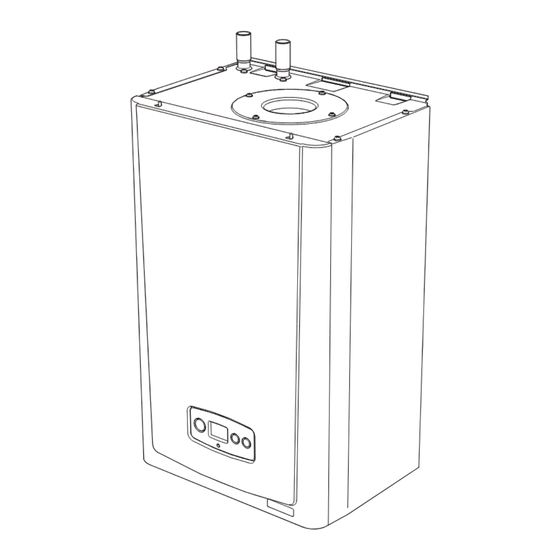
2 Boiler Dimensions and Hydraulic Schematic Diagram 2.2 2.1 Boiler Dimensions and Hydraulic Schematic All dimensions are given in millimetres (except as noted). The general arrangment of the boiler is shown in diagram 2.1. and the hydraulic and gas schematic, diagram 2.2. The data label is positioned on the front of the inner casing panel. -
Page 9: Boiler Location, Clearances And Ventilation
If the boiler is to be installed in a timber frame building it should be fitted in accordance with the Institute of Gas Engineers document IGE/UP/7/1998. If in doubt seek advice from the local gas undertaking or Glow-worm. 3.4 Combustible Material The boiler and flue are suitable for installation onto and... -
Page 10: Flue Options And Terminal Clearances
4 Flue Options and Terminal Clearances Ridge Tile Terminal Part No. A2043800 - Section 10, page 31 Plume Management Kit basic set, white, concentric flue (Ø60/100) - Part No. A2044100 for use with Part No. A2043400 and Part No. A2043600 - Section 10, page 36 Top horizontal standard flue (Ø60/100) Top horizontal telescopic flue (Ø60/100) -
Page 11: Flue Terminal Position
4 Flue Options and Terminal Clearances 4.1 Flue Options There are various flue options to choose from as illustrated in diagram 4.1. The flue lengths and installation are described in section 10. 4.2 Flue Terminal Position In GB the minimum acceptable siting dimensions for the terminal from obstructions, other terminals and ventilation openings are shown in diagram 4.2. -
Page 12: Water Systems 5
5 Water Systems - General 5.7 Water Treatment 5.1 General Existing system- It is ESSENTIAL that prior to installing the This boiler is designed to provide central heating from a fully new boiler the system is thoroughly flushed. pumped open vented or sealed water system and domestic hot water using a fully indirect cylinder. -
Page 13: Open Vented
5 Water Systems - Open Vented 5.8 Vented (Open) Water System The boiler must be supplied from an unrestricted water supply taken from a feed and expansion cistern situated at a maximum height of 27 metres (90ft) above the boiler. The cold feed must be 15mm minimum size. -
Page 14: Sealed Systems
5 Water Systems - Sealed 5.15 Pressure Gauge 5.12 Sealed Water Systems The installation must comply with the appropriate A pressure gauge with a set pointer and covering at least 0 to requirements of the current issue of BS4814, BS5449, 4 bar (0 to 60 lb/in2) shall be fitted permanently to the system BS6759, BS6798 and BS7074 Part 1 and 2. -
Page 15: Filling A Sealed Water System
5 Water Systems - Sealed 5.17 Water Makeup SUPPLY Provision should be made for replacing water loss from the PIPE system using a make up bottle mounted in a position higher than the top point of the system, connected through a non-re- turn valve to the return side of either the heating circuit or the BOILER hot water cylinder. -
Page 16: Installation Preparation
6 Installation Preparation 6.1 Appliance Pack BOILER SECURING Please check the contents of packs as shown in diagram 6.1. SCREW The packs are located in the top polystyrene packing. Remove the carton sleeve and top pack then lift the boiler and its polystyrene base support out of the lower pack. -
Page 17: Boiler Fixing
7 Boiler Fixing 7.1 Wall Hanging Bracket The Wall Hanging Bracket is supplied in the main boiler packaging. Reposition the wall template over the flue hole and mark the position of the fixing holes for the hanging bracket, see diagram 7.1. NOTE: Due to the varied site conditions we do not supply fixings and advise that the installer should supply those which are suitable. -
Page 18: Gas/Water And Appliance Connection
8 Gas / Water and Appliance Connection 8.1 Gas Connection 8.2 Water Connections Before connection check the supply of local gas. Provision is made for the water connections to be made from The gas supply connection is below the boiler, see diagram above the boiler, see diagram 8.1. - Page 19 9 Condensate Connections Diagram 9.2 Supplied By www.heating spares.co Tel. 0161 620 6677...
-
Page 20: Flue Length Preparation And Installation
10 Telescopic Flue - Length, Preparation and Installation 10.1 Flue Length Multiple Boiler Chimney Flue Length The flue length must be calculated and installed according to The maximum permissable horizontal flue length is 8 metres the relevant standards EN 13384-1 and 2 (C43 flue systems plus the flue terminal assembly, this can be achieved by use only) with reference to the table below and the manufacturers of the accessories, see diagram 10.3. - Page 21 10 Telescopic Flue - Length, Preparation and Installation Diagram 10.2 Diagram 10.3 Supplied By www.heating spares.co Tel. 0161 620 6677...
- Page 22 10 Telescopic Flue - Length, Preparation and Installation 10.2 Horizontal Telescopic Flue - A2043600 Refer to diagram 10.2 for kit contents. 10.3 REAR Flue If a wall thickness is between 231mm min. to 441mm max. then the flue can be used without extensions. Remove the top flue outlet cover secured with four screws, see diagram 10.4.
- Page 23 10 Telescopic Flue - Length, Preparation and Installation 10.5 Flue Fitting IMPORTANT:- The flue seals are sensitive to mineral oil based lubricants. Do not grease the seals. If the seals do need to be lubricated use only water. During the installation of the flue system, ensure that debris such as mortar, filings or swarf are cleared from the flue system before completion.
- Page 24 10 Standard Flue - Length, Preparation and Installation 10.6 Flue Length Multiple Boiler Chimney Flue Length The maximum permissable horizontal flue length is 8 metres The flue length must be calculated and installed according to plus the flue terminal assembly, this can be achieved by use the relevant standards EN 13384-1 and 2 (C43 flue systems of the accessories, see diagram 10.13.
- Page 25 10 Standard Flue - Length, Preparation and Installation Diagram 10.12 Diagram 10.13 Supplied By www.heating spares.co Tel. 0161 620 6677...
- Page 26 10 Standard Flue - Length, Preparation and Installation 10.7 Standard Horizontal Flue - A2043400 Refer to diagram 10.12 for kit contents. 10.8 REAR Flue Remove the top flue outlet cover secured with four screws, see diagram 10.4. Using these screws inserted into the same holes on the boiler, temporarily secure the flue elbow, measure the distance...
- Page 27 10 Standard Flue - Length, Preparation and Installation 10.10 Flue Fitting IMPORTANT:- The flue seals are sensitive to mineral oil based lubricants. Do not grease the seals. If the seals do need to be lubricated use only water. During the installation of the flue system, ensure that debris such as mortar, filings or swarf are cleared from the flue system before completion.
- Page 28 10 Direct Rear Flue - Length, Preparation and Installation 10.11 Direct Rear flue - Telescopic Part No. A2043500. Refer to diagram 10.19 for kit contents. 10.12 Flue Length Measure the distance from the outside wall to the inside wall face. This measurement must not exceed 512mm (465mm if the upward piping kit is used).
- Page 29 10 Vertical Flue - Length, Preparation and Installation 10.14 Vertical flue Alternatively use 45º bends to avoid horizontal runs, see (b) in diagram 10.22. The vertical flue system is available as an option where the The terminal siting should be as shown in diagram 4.2. boiler position does not permit the use of the top horizontal Measure the distance of flue length required for the flue system.
-
Page 30: Flue Installation
10 Vertical - Flue Length, Preparation and Installation Flue Installation IMPORTANT:- The flue seals are sensitive to mineral oil based lubricants. Do not grease the seals. If the seals do need to be lubricated use only water. During the installation of the flue system, ensure that debris such as mortar, filings or swarf are cleared from the flue system before completion. - Page 31 10 Vertical - Flue Length, Preparation and Installation Ridge Tile Terminal A ridge tile terminal is available - part no. A2043800, see diagram 10.24. The installation of a ridge tile will be required. A suitable ridge tile is manufactured by: - Aspect East Anglia Limited The Old Mill East Harling...
- Page 32 10 Vertical Flue Length, Preparation and Installation Completion of Installation With the flue terminal positioned in the roof the length of the final pipe can be determined. If a telescopic length cannot be used, then a standard flue length can be cut to make the correct length.
- Page 33 10 Twin Flue - Length, Preparation and Installation Secure long flue lengths (horizontal & vertical) to walls or ceiling at every joint or on straight flue runs at every joint and every metre flue run. Diagram 10.29 Supplied By www.heating spares.co Tel. 0161 620 6677...
-
Page 34: Terminal Position
10 Twin Flue - Length, Preparation and Installation Multiple Boiler Chimney Flue Length 10.15 Twin flue length The flue length must be calculated and installed according to The twin flue system is available as an option when the top horizontal or vertical flue system is not appropriate. the relevant standards EN 13384-1 and 2 (C43 flue systems The system can provide an independent horizontal air inlet only) with reference to the table below and the manufacturers... -
Page 35: Installation Details
10 Twin Flue - Length, Preparation and Installation Installation Details The parts available for a twin flue system installation are shown in diagram 10.30. Boiler Connection IMPORTANT: The flue seals are sensitive to mineral oil based lubricants. Do not grease the seals. If the seals do need to be lubricated use only water. - Page 36 2 x 45 bends the maximum length of the Plume Management Kit must be reduced by 1m. For more information contact Glow-worm, refer to page 2. The Plume Management Kit is supplied with installation instructions. Refer to BS5546 or BS6798 for advice on disposal of boiler condensate.
-
Page 37: Electrical Connection
● This appliance must be wired in accordance with these CARTRIDGE instructions. Any fault arising from incorrect wiring cannot be put right under the terms of the Glow-worm guarantee. ● All system components must be of an approved type. Electrical components have been tested to meet the equivalent requirements of the BEAB. -
Page 38: Commissioning
11 Electrical Connection 11.3 Electrical Cartridge Securing FIXING Close the cartridge and secure with the previously removed SCREWS screw. Push the electrical cartridge into the interface housing on completion of the wiring, see diagram 11.3. Secure with the two cartridge retaining screws provided in the cartridge body. -
Page 39: Initial Lighting
12 Commissioning MODE MODE Diagram 12.2 Commissioning should only be carried out by a competent After 10 seconds of inactivity the display will reset to indicate person approved at the time by the Health and Safety the water temperature. Executive. ●... -
Page 40: Heating System
12 Commissioning 12.7 Heating System Additionally the safe nominal maximum heat input of the appliance can be achieved at an inlet pressure down to Ensure that the external controls are calling for heat. 15mbar. Fully open all radiator valves, flow control valve and bypass NOTE: The BURNER PRESSURE cannot be measured. -
Page 41: Servicing
When replacing a part on this appliance, use only spare parts that you can be assured conform to the safety and performance specification that we require. Do not use reconditioned or copy parts that have not been clearly authorised by Glow-worm. If any electrical connections have been disconnected and after their connection, checks to the earth continuity, polarity, short circuit and resistance to earth must be repeated using a suitable multimeter, as described in section 14. - Page 42 CO/CO2 ratio is acceptable. Advice can be sought from the Glow-worm Technical Helpline. 13.1 Servicing NOTE: If the Combustion CO2, CO/CO2 ratio & Gas rate checks did not require adjustment then it will not be necessary to complete a full service.
-
Page 43: Spark Electrode
13 Servicing 13.4 Spark Electrode NOTE: If the functional checks did not indicate poor combustion then it is not necessary to service this component. Ease the securing clips away from the sump to release the retaining catch then push the flue hood up to disengage from the sump, see diagram 13.5. - Page 44 13 Servicing ELECTRICAL SECURING CONNECTIONS SCREW (3) SECURING SUPPORT BRACKET IGNITION LEAD SPADE CONNECTOR EARTH IGNITER Diagram 13.9 UNIT CONNECTION VALVE TUBING ELECTRICAL PIPE CONNECTION (removed) Diagram 13.7 RETAINING BRACKET SECURING Diagram 13.10 Diagram 13.8 Diagram 13.11 Supplied By www.heating spares.co Tel. 0161 620 6677...
-
Page 45: Service Completion
13 Servicing 13.8 Casing panel seal check 13.6. Heat Exchanger NOTE: If the functional checks did not indicate poor NOTE: If the functional checks did not indicate poor combustion then it is not necessary to service this combustion then it is not necessary to service this component. -
Page 46: Fault Finding
14 Fault Finding 14.1 Preliminary fault finding The following checks should be performed before proceeding onto specific diagnostics: • Check the external electrical supply to the boiler is on and a supply of 230V is present at the ‘L’ and ‘N’ terminals at the installer interface. - Page 47 14 Fault Finding BROWN BLUE GREEN/YELLOW GREY GREEN BLACK HEATING FLOW CONTROL YELLOW THERMISTOR VALVE WHITE ORANGE r w y PURPLE PINK HEATING RETURN THERMISTOR IGNITER UNIT bk bk b IGNITION ELECTRODE MAIN CONTROL BOARD APPLIANCE INTERFACE BOARD FLEXICOM HX Diagram 14.4 Supplied By www.heating spares.co Tel.
- Page 48 14 Fault Finding Diagram 14.5 Supplied By www.heating spares.co Tel. 0161 620 6677...
- Page 49 14 Fault Finding In all circumstances press the reset button to clear the fault. If the fault persists, consult the table below. FAULT CODES Diagram 14.6 Supplied By www.heating spares.co Tel. 0161 620 6677...
- Page 50 14 Fault Finding State list - To access the state lists the ‘-’ button must be pressed for longer than 5 seconds until it begins to flash ‘S’ and then a number to indicate the state. The state numbers are given below. STATE LISTS Diagram 14.7 Supplied By www.heating spares.co Tel.
- Page 51 14 Fault Finding To enter the diagnostics menu follow the procedure below:- Press and hold the ‘MODE’ and ‘+’ buttons for approx 5 seconds until the screen changes. Use the ‘+’ or ‘-’ button to select the number 96, this is the password. Hold the ‘MODE’ for approx 5 seconds when 96 is selected, when the screen changes release the button.
-
Page 52: Replacement Of Parts
15 Replacement of Parts 15.1 General 15.7 Fan/Gas valve assembly For access, refer to section 15.1. Replacement of parts must be carried out by a competent Undo the tubing nut to remove the gas valve from the gas pipe person approved at the time by the Health and Safety and any electrical connections, see diagram 13.7. -
Page 53: Condensate Trap
15 Replacement of Parts 15.10 Burner For access, refer to section 15.1. Remove igniter unit, flue hood, fan and gas valve assembly and spark electrode lead, refer to relevant sections. Remove the flanged nuts and studs that secure the burner, note that two studs at the rear also hold the fan clamping bracket, see diagram 13.10. -
Page 54: Heat Exchanger
15 Replacement of Parts 15.13 Heating Return Thermistor RETURN PIPE For access, refer to section 15.1. Refer to diagram 15.3. Remove the electrical connections from the thermistor. Remove the retaining clip from the return pipe. Remove the thermistor from the retaining clip. Note that the polarity of the wiring to thermistor is unimportant. - Page 55 15 Replacement of Parts Remove the burner Remove the heat exchanger Remove the six flanged nuts and two studs that secure the Undo the screws securing the flanged elbow on the top right burner, note that the two studs also hold the fan clamping hand side of the heat exchanger and remove the retaining clip bracket, see diagram 15.7.
- Page 56 15 Replacement of Parts 15.15 Casing Seal 15.18 Fuse - Main PCB - Control Box For access, refer to section 15.16. Refer to Section 13.8. The fuse is located at the top left hand corner of the main 15.16 Access to User interface and Main PCB, see diagram 15.8.
-
Page 57: Spare Parts
16 Spare Parts Key No. Part No. Description GC No 0020020734 H42723 0020020763 Igniter unit H42773 0020020781 Heating flow & return thermistor (2) H42792 0020020735 Gas valve 12hx - 30hx H42724 0020059600 Gas valve 35hx H69002 0020020731 Spark Electrode H42720 0020020728 Burner 12hx - 30hx H42718... -
Page 58: Manual Handling
17 Manual Handling IMPORTANT. of packaging in a responsible manner. Recommend wear suitable With regards to the Manual Handling Opera- cut resistant gloves with good grip to protect against sharp edges and tions, 1992 Regulations, the following lift operation exceeds the ensure good grip when handling appliance outside packaging. -
Page 59: Declaration Of Conformity
18 Declaration of Conformity Supplied By www.heating spares.co Tel. 0161 620 6677... - Page 60 0020057279 Glow-worm, Nottingham Road, Belper, Derbyshire. DE56 1JT Because of our constant endeavour for improvement, details may vary slightly from those shown in these instructions. Glow-worm, Nottingham Road, Belper, Derbyshire. DE56 1JT www.high-efficiency.info Supplied By www.heating spares.co Tel. 0161 620 6677...
Need help?
Do you have a question about the Flexivom 12hx and is the answer not in the manual?
Questions and answers