Table of Contents
Advertisement
Installation and Servicing
96
G.C. No. 47-047-25
Fanned Flue Combination Boiler
This is a Cat II
The instructions consist of three parts, User, Installation and Servicing Instructions, which include the Guarantee Registration Card.
The instructions are an integral part of the appliance and must, to comply with the current issue of the Gas Safety (Installation and Use)
Glow-worm appliances' are manufactured to the very highest standard so we are pleased
In the centre pages are to be found your Guarantee Registration Card, which we recommend you complete and
If this card is missing you can obtain a copy or record your registration by telephoning the Heatcall Customer
Our Guarantee gives you peace of mind plus valuable protection against breakdown by covering the cost of:
All replacement parts
All labour charges
All call-out charges
One Contact Local Service
Instructions for Use
To b e l e f t w i t h t h e u s e r
120
G.C. No. 47-047-26
Appliance
2H3+
Regulations, be handed to the user on completion of the installation.
Guarantee Registration
Thank you for installing a new Glow-worm appliance in your home.
to offer our customers' a Comprehensive First Year Guarantee.
return as soon as possible.
Service number 01773 828100.
Customer Services:
Tel: (01773) 828100
Fax: (01773) 828070
REGISTER YOUR GLOW-WORM APPLIANCE
FOR 1ST YEAR GUARANTEE PROTECTION
CALL 0208 247 9857
Nottingham Road, Belper, Derbyshire. DE56 1JT
Tel: (01773) 824141 Fax: (01773) 820569
2000221595.11.01
Hepworth Heating Ltd.,
General/Sales enquiries:
Advertisement
Table of Contents

Related Manuals for Glow-worm Xtrafast 96


Summary of Contents for Glow-worm Xtrafast 96
-
Page 1: Guarantee Registration
Guarantee Registration Thank you for installing a new Glow-worm appliance in your home. Glow-worm appliances' are manufactured to the very highest standard so we are pleased to offer our customers' a Comprehensive First Year Guarantee. In the centre pages are to be found your Guarantee Registration Card, which we recommend you complete and return as soon as possible. -
Page 2: Important Information
If you see any exception to this rule, please contact your nearest Glow-worm dealer. Thank you in advance for your assistance. -
Page 3: Table Of Contents
Contents CONTENTS DESCRIPTION SECTION PAGE No. Introduction Controls and Lighting INSTRUCTION Clock-timer instructions for use FOR USE Draining Safety Devices Servicing and Maintenance Technical Data Dimensions Heating System Design Domestic Hot Water System Design Boiler Schematic Boiler Location, Flue and Ventilation Fixing Jig Pack INSTALLATION Piping System Installation... -
Page 4: Instruction For Use
Introduction The XTRAFAST 96 and 120 boiler is a wall mounted modulating of 3mm on both poles. The switch should be readily accessible combination boiler with electronic ignition providing central and preferably adjacent to the appliance. It should supply the heating and instantaneous hot water. -
Page 5: Controls And Lighting
Controls and Lighting Lighting the boiler : Make sure that: • The boiler is connected to the electrical supply. • The gas service cock is open. Then follow the instructions below : Press the On/Off button (1) The pressure must be between 1 and 2 bar. If not, the system must be filled by a competent person. mode To stop the boiler : Press button (1) Setting to the SUMMER position... -
Page 6: Clock-Timer Instructions For Use
To have this done call registered person. If the valve discharges at any time, switch the a qualified service engineer or Heatcall (Glow-worm’s own service organisation) using the telephone number behind the boiler off and isolate it from the electrical supply. -
Page 7: Servicing And Maintenance
Safety valve, maximum service pressure (bar) Fuse rating 125mAT 125mAT Products outlet diameter (mm) Fresh air inlet diameter (mm) Xtrafast 96 Xtrafast 120 Hot water Lift weight 51.2kg (112.9lb) **.*kg (**.**lb) Hot water output automatically variable from ... (kW) 10,4... - Page 8 1 Technical Data PUMP 96 1000 1200 (10 kPa = 1 m WG) Flow rate through heating system (I/h) PUMP 120 1000 1200 (10 kPa = 1 m WG) Flow rate through heating system (I/h) Bypass fully shut Open 1/4 turn Open 1/2 turn Open 1 turn Open 2 turns...
-
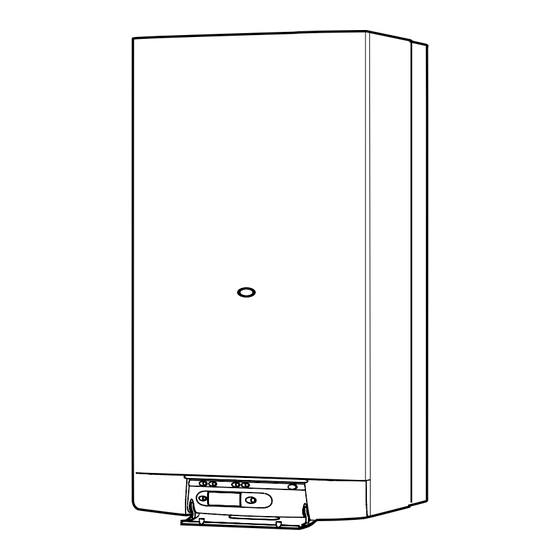
Page 9: Dimensions
2 Dimensions The XTRAFAST is delivered in three separate packages: - the boiler - the fixing jig - the flue system Lifting Weight: 51,2 kg X = 470 (96) 552 (120) Diagram 5 3 Heating System Design • The total volume of water permitted for the heating system •... -
Page 10: Domestic Hot Water System Design
4 Domestic Hot Water System Design • Copper tubing or plastic hep o may be used for the domestic bar, but under reduced flow rate. Best operating comfort will be hot water system. Unnecessary pressure losses should be obtained from a supply pressure of 1 bar. avoided. -
Page 11: Boiler Location, Flue And Ventilation
PROVIDING that adequate consideration is given for Servicing/Repairs at a later date. If Extentions, 90° and 45° bends. any doubt exists, contact the Glow-worm Technical Helpline Flue options and accessories. 01773 828100. For detailed information refer to flue guide Part No. 223278. -
Page 12: Fixing Jig Pack
7 Fixing Jig Pack The fixing jig is made up, from left to right, as follows: Other components within the fixing jig pack. A - Heating return fitting with isolating valve(v) and F - Hanging bracket drain knob (u). G - wall template B - Cold water inlet fitting with isolating valve (m)and H - copper connections factory fitted flow regulator and filter (not shown). - Page 13 The boiler must be installed so that the terminal is exposed to the external air. Should any doubt exist as to the permissible position of the terminal, contact the Glow-worm Technical Helpline 01773 828100. 8.7 Water connection Connect the system pipework to the copper connections on the fixing jig observing the correct flow and return format as shown in diagram 8.2.
-
Page 14: Boiler Installation
9 Boiler installation 9.1 Statutory requirements The installation of this boiler must be carried out by a qualified registered person in accordance with the relevant requirements of the current issue of: The Gas Safety (Installation and Use) Regulations The Building Regulations The local water company Byelaws The Building Standards Regulations (Scotland) The Health and Safety at Work Act... -
Page 15: Flue Installation
10 Flue Installation 10.1 Top outlet flue - kit 86285 The boiler is only suitable for top outlet flue connection. 70mm 70mm 10.2 Rear flue systems (Refer to diagram 10.1). To calculate the length when flueing to the rear measure wall thickness e plus 160 mm for the outer air duct and e plus 244 mm for the inner flue duct measurement. - Page 16 10 Flue Installation 10.4 Installation of flue assembly • Fit rubber sealing collar (F), see diagram 10.3, into groove at the outer end of pipe (A). • Fit air duct pipe (A) into wall with groove to the outside. • Pull pipe inwards to bring rubber sealing collar hard up against external wall, see diagram 10.4.
-
Page 17: Electrical Connection
Warning: This appliance must be wired in accordance with these instructions. Any fault arising from incorrect wiring cannot be put right under the terms of the Glow-worm guarantee. 11.1 External controls The XTRAFAST boiler is designed to operate at maximum efficiency at all times, but will be most efficient and economical when connected to a room thermostat. -
Page 18: Commissioning
12 Commissioning Please ensure the “Benchmark” logbook is completed and left with the user. The commissioning and first firing of the boiler must only be done by a qualified registered person. Gas valve settings. Refer to Section 15 "Settings". Gas installation It is recommended that any air is purged from the supply at the gas inlet test point on the gas valve, see diagram 12.1. - Page 19 12 Commissioning Leave the cap on the Open various hot water Bleed each radiator to pump auto air vent open. taps to bleed system. remove the air, re-tighten bleed screws. Make sure the display indicates a system pressure of between 1 and 2 bar. Re-fill system as necessary.
-
Page 20: Commissioning 12
12 Commissioning Lighting the boiler: Make sure that: • The boiler is connected to the electrical supply. • The gas service cock is open. Then follow the instructions below : Press the On/Off button (1) The pressure must be between 1 and 2 bar. If not, the system must be filled by a competent person. mode To stop the boiler: Press button 1. -
Page 21: Safety Devices
13 Safety Devices General safety devices The XTRAFAST incorporates a visual display that indicates fault conditions, should they occur. 13.4 Air flow rate safety device In the event of a fault, the display will indicate, by means of If an obstruction, even partial, of the flue occurs, for any reason pictograms and/or letters and numbers, exactly in which area whatsoever, the built in safety system of the boiler will turn the the fault lies. -
Page 22: Changing Gas Type
14 Changing Gas Type Should it become necessary to change the gas type, a modification kit will be required. This modification must only be carried out by a suitably qualified engineer. Conversion natural Gas (G20) to G30/G31 Part No. 86216. 15 Settings Bypass The XTRAFAST boiler has a built-in bypass. -
Page 23: Routine Cleaning And Inspection
16 Routine Cleaning and Inspection To ensure the continued efficient and safe operation of the boiler it is recommended that it is checked and serviced at regular intervals. The frequency of servicing will depend upon the particular installation conditions and usage, but in general once a year should be enough. - Page 24 16 Routine Cleaning and Inspection 16.8 Burner, refer to diagram 16.4. 16.9 Heat exchanger, refer to diagram 16.5. • Undo main gas supply nut from under the sealed chamber. • Disconnect electrical leads from fan. Note: The washer between main burner and main burner gas •...
- Page 25 16 Routine Cleaning and Inspection 16.10 Spark and Sense Gaps • Check that the spark and sense gaps as shown in diagram 16.6. 16.11 Flue system • Check externally to make sure that flue is not blocked • Inspect flue system to make sure that all fittings are secure. 16.12 Operation of fan •...
-
Page 26: Fault Finding
17 Fault Finding Fault finding must be carried out by a competent person. • There is a permanent mains supply to the boiler. WARNING. Always isolate the boiler from the electrical supply • The heating system pressure is at least 1 bar. before carrying out any electrical replacement work. - Page 27 17 Fault Finding TO AID FAULT FINDING REFER TO DIAGRAMS 5.1 AND 18.1. CODE TYPE OF FAULT DISPLAY SYMBOL CHECK NO FAULT NO FAULT THIS SYMBOL IS NOT INSTANTANEOUS BUT IF IT APPEARS AFTER 40 SECONDS, CHECK AIR FLOW SAFETY •...
-
Page 28: Wiring Diagram
18 Wiring Diagram IGNITION SENSE IGNITION ELECTRODES ELECTRODE MODULE g/y br SENSOR AIR PRESSURE SWITCH WATER PRESSURE SENSOR CONTROL VALVE THERMISTOR OVERHEAT THERMISTOR CHASSIS EARTH THERMISTOR HEATING ELEMENT FLOW SENSOR THREE-WAY VALVE CLOCK-TIMER PLUG STORAGE VESSEL THERMISTOR PUMP CH 230V~50Hz CHASSIS PERMANENT EARTH... -
Page 29: Replacement Of Parts
19 Replacement of Parts IMPORTANT INFORMATION DOMESTIC WARNING: Before commencing the replacement of any HOT WATER component, isolate appliance from electrical supply and turn off THERMISTOR gas at service cock. Replacement of parts must be carried out by a competent person. - Page 30 19 Replacement of Parts 19.5 Air pressure switch, refer to diagram 19.4 Before starting refer to the front of Section 19 Important AIR PRESSURE information. SWITCH • Remove the front panel, refer to Section 16.3. • Lower the control panel, refer to Section 16.4. •...
- Page 31 19 Replacement of Parts Note: These valves are closed when slots are at right angles to PIPE PLATE TO PLATE direction of flow. CONNECTION HEAT EXCHANGER • Drain boiler by opening drain valves (r) and (u), see diagram 7.1. Note: it is not necessary to drain down the entire heating system to carry out this work.
- Page 32 19 Replacement of Parts 19.10 Three-way valve head, refer to diagram 19.9. Before starting refer to the front of Section 19 Important information. • Remove the front panel, refer to Section 16.3. • Lower the control panel, refer to Section 16.4. •...
- Page 33 19 Replacement of Parts 19.14 Gas control valve stepper motor, refer to SPARK IGNITION UNIT diagram 19.13. Before starting refer to the front of Section 19 Important information. • Remove the front panel, refer to Section 16.3. • Lower the control panel, refer to Section 16.4. •...
- Page 34 Note: Apply a small quantity of silicon grease to the safety valve 19.16 Gas safety valve, refer to diagram 19.13. 'O' ring prior to fitting. Before starting refer to the front of Section 19 Important • Open isolating valves on flow and return connections, refill, information.
- Page 35 19 Replacement of Parts • Open isolating valves on flow and return connections, refill, vent and pressurise boiler. • Check for leaks. 19.21 Overheat thermostat, refer to diagram 19.15. Before starting refer to the front of Section 19 Important information. •...
- Page 36 19 Replacement of Parts 19.23 Burner INJECTOR BAR Before starting refer to the front of Section 19 Important information. • Remove the front panel, refer to Section 16.3. • Lower the control panel, refer to Section 16.4. • Remove the sealed chamber cover, refer to Section 16.5. •...
- Page 37 19 Replacement of Parts 19.27 User interface board assembly, refer to diagram 19.17. Before starting refer to the front of Section 19 Important information. • Remove the front panel, refer to Section 16.3. • Lower the control panel, refer to Section 16.4. •...
- Page 38 19 Replacement of Parts 19.30 Domestic Hot water storage vessel, refer to diagram 19.19. For this operation the boiler must be removed from the wall. CLIP POSITIONS Before starting refer to the front of Section 19 Important information. (2 OFF) •...
- Page 39 19 Replacement of Parts 19.31 Storage vessel thermistor, refer to DOMESTIC HOT diagram 19.20. WATER STORAGE VESSEL For this operation the boiler must be removed from the wall. Before starting refer to the front of Section 19 Important information. • Drain down central heating and domestic hot water circuit of boiler only, refer to relevant parts of Sections 16.13 and 19.8.
-
Page 40: Spare Parts
19 Replacement of Parts 19.33 Expansion vessel, refer to diagram 19.22. UNION NUT For this operation the boiler must be removed from the wall. RETAINING Before starting refer to the front of Section 19 Important information. • Drain down central heating and domestic hot water circuit of boiler only, refer to relevant parts of Sections 16.13 and 19.8.
Need help?
Do you have a question about the Xtrafast 96 and is the answer not in the manual?
Questions and answers