
Related Manuals for Sony UP-D25MD


Summary of Contents for Sony UP-D25MD
-
Page 1: Instructions For Use
4-152-259-15(1) Digital Color Printer Instructions for Use Before operating the unit, please read this manual thoroughly and retain it for future reference. UP-D25MD © 2009 Sony Corporation... - Page 2 This equipment generates, uses, and can radiate radio Record these numbers in the space provided below. frequency energy and, if not installed and used in Refer to these numbers whenever you call upon your Sony accordance with the instruction manual, may cause dealer regarding this product.
- Page 3 UP-D25MD. Guidance and manufacturer’s declaration-electromagnetic emissions The UP-D25MD is intended for use in the electromagnetic environment specified below. The customer or the user of the UP-D25MD should assure that it is used in such an environment. Emission test Compliance...
- Page 4 Guidance and manufacturer’s declaration - electromagnetic immunity The UP-D25MD is intended for use in the electromagnetic environment specified below. The customer or the user of the UP-D25MD should assure that it is used in such as environment. IEC 60601 test...
- Page 5 Guidance and manufacturer’s declaration - electromagnetic immunity The UP-D25MD is intended for use in the electromagnetic environment specified below. The customer or the user of the UP-D25MD should assure that it is used in such as environment. IEC 60601 test...
- Page 6 Recommended separation distances between portable and mobile RF communications equipment and the UP-D25MD The UP-D25MD is intended for use in an electromagnetic environment in which radiated RF disturbances are controlled. The customer or the user of the UP-D25MD can help prevent electromagnetic interference by maintaining a minimum distance between portable and mobile RF communications equipment (Transmitters) and the UP-D25MD as recommended below, according to the maximum output power of the communications equipment.
-
Page 7: Table Of Contents
Microsoft and Windows are registered trademarks of Table of Contents Microsoft Corporation. Other company names and product names mentioned in this guide are also trademarks and registered trademarks. Introduction Features ..............8 System Configuration .........8 Location and Function of Parts and Controls ..8 Front ..............8 Rear ..............9 Preparation... -
Page 8: Introduction
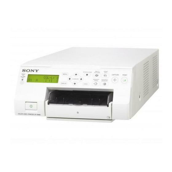
Parts and Controls Features Front The UP-D25MD Digital Color Printer is a dye sublimation thermal transfer printer providing high speed printing of computer image data on A6 paper in full color (256 gradations process and 16.7 million colors) and at high resolution (423 dpi precision head). -
Page 9: Rear
K Tray light Rear Illuminates the output tray. (You can configure the setting for this.) (page 18) Inside the Ribbon Door Panel A USB cable stopper (page 10) Secures the USB cable to prevent it from being disconnected. USB connector Connects to a computer equipped with a Hi-Speed USB (USB 2.0 compliant) interface. -
Page 10: Preparation
USB Port Connection Paper feed tray (1) UP-D25MD Stopper (1) to - AC IN connector (USB) connector USB cable 1-824-211-41 (SONY) (1) Before Using This Printer (1) Thermal head cleaning cartridge (1) USB cable Power cord (supplied) to wall outlet Computer... -
Page 11: Installing The Printer Driver
• Printer operation is not guaranteed for USB hub connections. Installing the Printer Driver For computers running on Windows 2000/ Windows XP/Windows Vista After connecting the printer to your computer, turn on the printer. For details on installation, refer to the installation guide and Readme file included on the supplied CD-ROM. -
Page 12: Operation
2 Switch the position of the media switch lever. Operation UPC-21S/UPC-21L: In UPC-24SA/UPC-24LA: Out Before Printing Once the printer is connected to the computer (page 10), you must load the paper and the ink ribbon as described below before you can actually begin printing. 3 Replace the cover. - Page 13 Load the ink ribbon. Slide the ribbon tray straight into the printer until 1 Align the two pegs on each side of the ink ribbon completely inserted. with the slots on the ribbon tray. Close the ribbon door panel. Notes •...
-
Page 14: Loading The Paper
3 Neatly stack and load the paper in the paper feed Loading the Paper tray, aligning the “v” mark on the protective sheet Follow the steps below to load paper into the paper feed with the “f” mark inside the tray. tray and to insert the tray into the printer. - Page 15 • When handling the paper, do not touch the print • Do not allow more than 10 printouts to accumulate. side. Fingerprints and dust may adhere to the print Leaving too many printouts in the output tray could side and soil it. To prevent the print side from cause a paper jam.
-
Page 16: Adjustments And Settings On The Menu
Menu Structure Adjustments and When the LCD display is in the ready state, pressing the Settings on the Menu MENU button displays the menu. With the menu displayed, each setting can be selected and configured with the directional buttons (<, ,, M, m). The menu allows you to adjust the color of prints and Press the MENU button while the menu is displayed to configure printer settings to suit your printing needs. -
Page 17: Menu List
Menu List Item Description Settings 1 Standard CURVE Switches the tone Descriptions of the settings available for each menu item curve. 2 High contrast are listed below. 3 Low contrast Default settings appear in bold. ADVANCE Configures detailed color COLOR Menu settings. -
Page 18: Using The Menu
SETUP Menu The backlight on the LCD display lights green, and the PRINT and ALARM indicators and tray light light Item Description Settings simultaneously before turning off. MODE 1 Ready (OFF) t LAMP Sets the operation Confirm that the LCD display is in the ready state of the output tray Receiving image (flashing) t... -
Page 19: Printing A List Of Printer Settings
Press < or , to select [COLOR]. Printing Press M or m to select [LOAD COL]. Before printing Press < or , to select a configuration number. • Is the printer connected to a computer? (page 10) • Have the ink ribbon and paper been properly loaded? Number Description (page 12) - Page 20 • Do not allow more than 10 printouts to accumulate. Leaving too many printouts in the output tray could cause a paper jam. When printing is disabled Printing is disabled when the ribbon door panel is open or the ALARM indicator is lit. For details, see “Explanation of Indicators”...
-
Page 21: Miscellaneous
Lock the internal thermal head. Miscellaneous 1 Press the ! POWER switch to turn on the printer. 2 Simultaneously press <, ,, and the MENU button. The printer operation sound continues for approximately 2 seconds, and the message Precautions “WAIT” appears on the LCD display. 3 When the printer operation sound stops and the In addition to the following precautions, be sure to refer to message “TRANS MODE”... -
Page 22: Cleaning The Thermal Head
Once the thermal head cleaning cartridge is loaded Cleaning the thermal head and the ribbon door panel is closed, the message If marks and stripes appear on printouts, clean the thermal “PRESS:EXEC” appears on the LCD display. head using the supplied thermal head cleaning cartridge and cleaning sheet. -
Page 23: Ink Ribbon And Paper
Select “CLEAN ROL” in the setup menu (page 16) Ink Ribbon and Paper and press ,. The message “PRESS:EXEC” appears on the LCD display. Do not re-use Doing so may result in malfunction and negatively Press the EXEC button. affect printing results. The manual paper feed roller cleaning operation begins and “CLEANING”... -
Page 24: Specifications
Hi-Speed USB (USB 2.0 compliant) Input connector AC IN (for power input) Supplied accessories Paper feed tray (1) Stopper (1) USB cable 1-824-211-41 (SONY) (1) Before Using this Printer (1) Software License Agreement (1) Thermal head cleaning cartridge (1) CD-ROM (printer driver/instructions for... -
Page 25: Troubleshooting
The EXTERNAL DEVICE. thermal head unlocks, and the • SONY WILL NOT BE LIABLE FOR DAMAGES OF ANY ink ribbon can be loaded. KIND INCLUDING, BUT NOT LIMITED TO, • The ink ribbon is not inserted in COMPENSATION OR REIMBURSEMENT ON the correct position. -
Page 26: Explanation Of Indicators
Symptom Possible causes and remedies Explanation of Indicators There are marks and The thermal head is dirty. tPerform thermal head cleaning stripes on the print side. (page 22). The meanings of the indicators on the printer when they are on or flashing are described below. Indicator LCD display Meaning... - Page 27 The base plate is not and then on again. If attached. the error message tAttach the base plate persists, consult (page 28). your Sony dealer. Off* RMV PRINTS The output tray is full TR HEAD 01 The thermal head is of printouts.
-
Page 28: Clearing A Paper Jam
** Lights only if 51 displayed. When contacting your Sony dealer for assistance, be sure to provide the error message and numeric value (if appicable) that appears on the LCD display. Clearing a Paper Jam Once printing starts, if the ALARM indicator lights and... - Page 29 Lift up the base plate and remove it from the printer. Note The printer cannot print with the base plate removed. Carefully clear the jammed paper. If a paper jam still cannot be cleared Consult your Sony dealer. Do not attempt to remove the paper by force. Explanation of Indicators...
- Page 30 Sony Corporation...
Need help?
Do you have a question about the UP-D25MD and is the answer not in the manual?
Questions and answers