Table of Contents
Advertisement
Quick Links
Advertisement
Table of Contents

Related Manuals for Celestron AllView Mount


Summary of Contents for Celestron AllView Mount
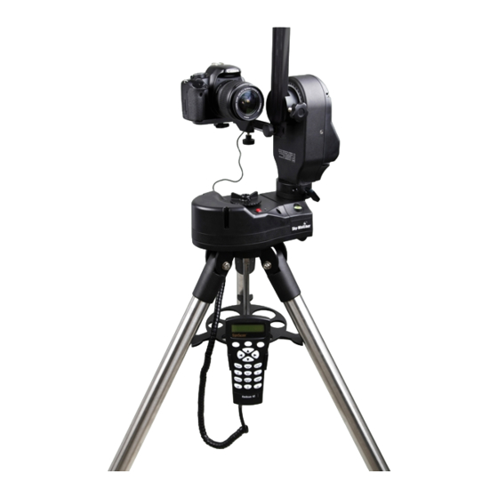
- Page 1 Multi-Purpose Computerized Mount Instruction Manual...
-
Page 2: Table Of Contents
Inner Mounting Configuration: ..........................Outer Mounting Configuration: ..........................Changing the Fork Arm Configuration ........................Dual Encoders and Mount Axis Clutches ....................... Powering the AllView Mount ..........................Using the AllView™ Mount for Panoramic Photography........................AllView Mount Panoramic Control ............................Easy Pano Mode .............................. - Page 3 Updating the SynScan™ Firmware ..............................System Requirements .............................. Preparing for the Update ............................Updating the SynScan AZ Hand Control ........................ SynScan™ AZ Menu Tree ..................................Appendix A – RS-232 Connection ............................... Additional RS-232 Commands ............................... Sending a track rate through RS-232 to the hand control ..................Sending a slow-Goto command through RS-232 to the hand control ..............
-
Page 4: Introduction
• An alt-azimuth go-to computerized astronomical mount (using an optional telescope optical tube) • A motorized platform for taking panoramic photographs • A stable platform for panning while taking time lapse video or still images • A motorized base for smooth panning video Sky-Watcher mounts carry a two year limited warranty. For details see our website at www.celestron.com Some of the many standard features of the AllView mount include: • Multi-purpose mounting bracket for attaching an optical tube, still camera, or video camera • Dual optical encoders - the mount never loses position even when moved by hand • Sturdy stainless steel tripod •... -
Page 5: Assembly
Camera shutter cable (for most Canon Rebel cameras) • RS-232 cable Assembling the AllView™ Mount Start by removing the AllView mount from its shipping carton and removing all of the accessories from their individual boxes. Remember to save all of the containers so that they can be used to transport or store the mount. Tripod and Mount Setup The AllView mount is shipped with the tripod already attached. To set up the mount and tripod: Slowly loosen the height adjustment screws and gently pull out the lower section of each tripod leg. Tighten the screws to hold the legs in place, as shown in Fig. 1. Spread the tripod legs apart to stand the tripod and mount upright, as shown in Fig. 2. Fig. 1 Fig. 2 Adjust the height of each tripod leg until the mount is properly leveled. There is a leveling bubble provided on the mount’s base... -
Page 6: Assembling And Installing The Mounting Bracket
Attach the accessory tray by sliding it along the primary locking shaft until it pushes against the tripod legs. Secure the locking knob, as shown in Fig. 3. Fig. 3 Install the hand control holder by sliding it into the accessory tray notch as shown in Fig 4. Push until it locks in place. ... - Page 7 The mounting bracket can be configured in two ways to hold a camera in landscape or portrait orientation. Landscape Orientation: Attach the Dovetail Bar (a) to the Guiding Rail (b) using the Now attach the Landscape Mounting Plate (c) to the hand screw as shown in Fig. 6. Guiding Rail (b) as shown in Fig. 7. Fig. 7 Fig. 6 Slide the Landscape Mounting Plate (c) along the Guiding Rail (b) back and forth to find a suitable position for the camera you are attaching. Tighten the hand screw on the Landscape Mounting Plate (c) to secure it in place. Loosen the altitude clutch knob on the AllView mount’s fork arm, as shown in Fig. 8, and turn the altitude axis, so the dovetail holder is in a vertical position. Retighten the clutch knob. Loosen the Dovetail Holder’s hand screw located on the fork arm and slide the mounting assembly into the dovetail holder. Tighten the hand screw. The mount should now look like Fig. 9. Fig. 9 Fig. 8...
- Page 8 Use the ¼-20 mounting screw on the Landscape Mounting Plate to attach your camera, camcorder or telescope optical tube as shown in Fig. 10 and Fig. 11. WARNING Do not over tighten the ¼-20 mounting screw or it may cause damage to the screw or camera body Fig. 10 Fig. 11 The camera position may be adjusted in 3-dimensions on the mounting bracket, as shown in Fig. 12, by: a. Up and down (Z axis) – adjust the Dovetail Bar in the fork arm dovetail holder b. Forward and backward (Y axis) – adjust the Landscape Mounting Plate along the Guiding Rail c. Left and right (X axis) – adjust the camera mounting bolt on the Landscape Mounting Plate Fig. 12...
- Page 9 Portrait Orientation: The Portrait Mounting Plate Assembly (d) is made up of two pieces – the Mounting Plate (d1) and the Dovetail Bar Clamp (d2). To separate them, loosen the hand screw as shown in Fig. 13 and Fig. 14. Fig. 13 Fig. 14 Slide the Mounting Plate (d1) and the Dovetail Bar Clamp (d1) (d2) apart as in Fig. 15. Mounting Plate (d1) Portrait Mounting Plate Assembly Dovetail Bar Clamp (d2) (d2) Fig. 15 Attach the Mounting Plate (d1) to your camera using the ¼-20 screw as shown in Fig. 16. Fig. 16 WARNING Do not over tighten the ¼-20 mounting screw or damage may occur to the screw or camera body...
- Page 10 Slide the short guiding rail on the Mounting Plate (d1) into the Fig. 17 guiding rail slot on the Dovetail Bar Clamp (d2) and secure it in place using the hand knob as shown in Fig. 17. Slide the Dovetail Bar (a) into the Portrait Mounting Plate (d) and secure using the hand screw as shown in Fig. 18 and Fig. 19. Fig. 18 Fig. 19 Note: When assembling the Portrait Mounting Plate (d), make sure that the Mounting Plate (d1) is positioned high enough to prevent the ¼-20 screw from obstructing the Dovetail Bar’s (a) path when you assemble the two pieces.
- Page 11 Loosen the dovetail holder’s hand screw on the fork arm and slide the Dovetail Bar (a) into the dovetail holder. Secure using the hand screw. The mount should now look like Fig. 20 and Fig. 21. Fig. 20 Fig. 21 The camera’s position may be adjusted in 3-dimensions on the Portrait Mounting Bracket, as shown in Fig. 22. a. Forward and backward (X axis)– adjust the Portrait Mounting Plate (d) along the Dovetail Bar (a) b. Left and right (Y axis) – adjust the Mounting Plate (d1) on the Dovetail Bar Clamp (d2) Fig. 22...
-
Page 12: Fork Arm Configuration
Fork Arm Configuration There are two configurations for the Fork Arm which are useful for both astronomy and photography. Inner Mounting Configuration: The inner fork arm configuration, as shown in Fig. 23, is designed to be used when attaching a camera to the AllView mount for panoramic photography. This allows the camera to be set up at a nodal point, where it is close to the intersection of the altitude and azimuth axes. A telescope optical tube may also be used in this configuration, but long telescope optical tubes may be limited in their altitude movement as they may strike the mount. For long tubes and camera lenses, you should use the Outer Mounting Configuration described below. • When using a camera for panoramic photography, a video camera for video coursing, or a compact short tube telescope with the fork arm in the inner configuration, the fork arm should be at your left hand side while you are standing behind the mount as shown in Fig. 23. • When using a telescope or binocular for astronomical observing with the fork arm in the inner configuration, the fork arm should be at your right hand side while you are standing behind the mount as shown in Fig. 24. Fig. 23 Fig. -
Page 13: Changing The Fork Arm Configuration
Changing the Fork Arm Configuration To change the fork arm configuration, loosen the hand screw, located near the base of the fork arm, rotate the fork arm 180˚ until it stops and tighten the set screw as shown in Fig 26 through Fig 29. Fig. 26 Fig. 27 Fig. 28 Fig. 29 Note: When a camera or telescope optical tube is attached with the fork arm on the incorrect side as described above, the camera or telescope’s UP and DOWN movement will be reversed and the mount will not function correctly. -
Page 14: Dual Encoders And Mount Axis Clutches
An optional AC adapter can be attached using the power port on the base of the mount or you can use ten (10) AA alkaline batteries in the built-in battery compartment. The battery compartment is located inside the bottom of the AllView mount head. To access the battery compartment: Separate the mount from the tripod by loosening the three tripod mounting bolts underneath the tripod head (see Fig. 30) Turn the mount over and locate the two knurled thumb screws. -
Page 15: Using The Allview™ Mount For Panoramic Photography
Using the AllView™ Mount for Panoramic Photography AllView Mount Panoramic Control The AllView mount is a multi-functional camera mount and tripod. Not only can it be used as a computer controlled telescope mount, it can also be used as a motorized tripod for photography or video recording as well. The AllView mount and the panoramic functionality of the SynScan AZ hand control will work as a panoramic controlled mount and head. There are three methods for shooting panoramic images – Easy Pano Mode, Preset Pano Mode and Time Lapse Mode. Easy Pano Mode This is a simple and straightforward method for people just getting started in panoramic photography. - Page 16 The hand control will display “Step 1: Set Camera FOV…” and “Already know the FOV?” • If you already know the field of view of the camera lens you are using, Press 1. The hand control will then ask you to use the numeric keypad to enter the field of view (in degrees) of the horizontal axis first. When you are done, press ENTER and edit the field of view of the vertical axis. • If the field of view is unknown, press 2. The hand control will walk you through the steps on measuring the field of view of your lens in both the horizontal and vertical axes. If your camera is so equipped, turn on the LCD’s live preview mode, otherwise use your viewfinder. The mount will ask you to use the directional keys to move the mount in the following manner: • Align the top frame of the camera’s view with the horizon and press ENTER • Align the bottom frame of the camera’s view with the horizon and press ENTER The hand control will now display the measured field of view for the vertical axis of your lens. To continue, press 3. If you wish to go back and perform the measurement again, press 1.
- Page 17 The hand control will display “Step 4 Set Shooting” and “Set Time Halt.” Using the numeric keypad, enter the number of seconds you would like to halt the mount between shots and press ENTER. The hand control will ask if you want to continue with Auto Shooting. • By pressing the 1 key, AllView will work in auto-shooting mode, which will send signals via the electronic shutter release cable to the camera to automatically release the shutter for each shot in the panorama.
-
Page 18: Preset Pano Mode
Preset Pano Mode This method is for more advanced users that want to edit and preset user defined picture points. You will do this by creating a series of layers. Each layer will specify the altitude angle that you want to shoot and how many images you want the mount to take in a 360˚ panorama at that altitude setting. By adding additional layers at different altitudes, you have the ability to take a full 360˚ panorama from straight overhead to the base of the mount! Select Preset Pano Mode and press ENTER. The hand control will prompt you to select a camera. There are two preset memory locations available for you to customize with name or model and field of view parameters. If this is your first time using the mount, or you have not configured your camera information into these memory locations, you can simply select one of the two undefined CAM #1 or CAM #2 and press ENTER. The hand control will ask if you want to edit the preset layers. - Page 19 The hand control will ask if you wish to exit the layer editor. Press 1 to exit the editor and press 2 to continue adding or deleting layers. Once you exit the layer editor, the hand control will ask if you want to save your current layer configuration for use in the future, Press 1 to save the changes you made. Note: There are two layers called Zenith and Nadir. Zenith refers to the point straight overhead, while Nadir refers to the spot directly below the mount.
-
Page 20: Time Lapse Mode
Time Lapse Mode This feature allows you to collect a series of still images over a long period of time while the mount slowly pans. You can then use your favorite image processing software to merge these frames into a time lapse video. From the Panoramic Function menu, use the scroll keys to select Time Lapse Mode. Press ENTER to continue. It is recommended that you use your camera’s “Live Preview” mode to use the LCD display as the viewfinder. If your camera does not have this option, you may use the optical viewfinder. Use the directional keys to move the camera to the point where you wish to start your slow pan. Press ENTER to continue. Use the directional keys where you want the slow pan to end and press ENTER. The display will prompt you to set the amount of time you want between each picture point in your time lapse pan. You may enter the information using the directional keys and the numeric keypad in the following format: h:mm:ss. The time interval you can enter is 9:59:59. Once you have entered the proper time interval, press ENTER. -
Page 21: Slew To Home
Press ENTER to bring up the letter choices on the top line of the display. Use the directional buttons to select the letter you want and press ENTER. Press ENTER again to select the second letter. Continue until you have finished. You can press the scroll buttons to change the case of the letters to choose from or select numbers or special characters. When you are done entering the name, press SETUP. -
Page 22: Using The Allview™ Mount For Astronomy
Using the AllView™ Mount for Astronomy The SynScan™ AZ System The AZ GOTO MODE provides extensive computerized GO-TO function to assist you in finding and enjoying the treasures of the night sky, such as planets, nebulae, star clusters, galaxies and much more. The hand control allows you to point your telescope to a specific object or even tour the skies at the touch of a button. The user-friendly menu system allows automatic slewing to over 42,900 objects. Even a beginning amateur astronomer can master its variety of features in a few observing sessions. The SynScan AZ Hand Control The SynScan AZ hand control has three ports on its bottom edge as pictured in Fig. 35. The hand control cable has a RJ-45 with 8 connecting pins on one end and a RJ-12 connector with 6 pins on the opposite end. - Page 23 The SynScan AZ hand control allows direct access to all the motion controls of the telescope and a database with a range of preset objects. The hand control comes with a dual-line, 16-character display that is backlit for comfortable viewing of telescope information and scrolling text. To explore the many functions the SynScan AZ has to offer, there are 4 main groups of keys on the hand control (Fig. 36). Fig. 36 Mode Keys: The mode keys are located near the top, close to the LCD display. They include: ESC key is used to escape from a certain command or to go back a level in the menu tree • • SETUP key is a quick hot key that takes you to the Setup submenu • ENTER key is used to select the functions and submenu in the menu tree and to confirm certain functional operations Directional Keys: The directional keys allow complete telescope control at almost any step in SynScan’s operation. These controls are locked out when the telescope is slewing to an object. They are normally used to initially align, center objects in the eyepiece and when manually guiding. The left and right directional keys can also be used to move the text cursor when entering data into the hand control. Scroll Keys: The up and down scroll keys, shown in Fig. 37, allow you to scroll up and down within the menu tree or selections.
-
Page 24: Az Goto Operation
Dual Purpose Keys: These keys, pictured in Fig. 38 and Fig. 39, range from the middle to the bottom of the hand control. They serve two distinct purposes – data entry and quick reference hot keys: TOUR key takes you on a preset tour across the sky you are currently under • • RATE key changes the speed rate of the motors when the directional keys are pressed. There are 10 speeds to choose from: 0 (slowest) to 9 (fastest) •... - Page 25 The hand control will prompt “SET LOCATION:” on the display. There are two methods of performing this function. Use the scrolling keys to select the method you wish to use and press ENTER. • Select City: The hand control will ask you to select a database of cities, either in the United States or an International city. In the United States database, you will first select your state and then the closest city to you in alphabetical order. In the International database, you will first select the country and then the city in alphabetical order. If your exact city is not listed, choose the nearest city in the database. As long as you are within 75 miles of the city you choose, you should still be able to easily align the telescope. • Edit Coordinates: You may directly enter your longitude and latitude into the hand control using the numeric keypad.
-
Page 26: Star Alignment
Star Alignment In order for the SynScan AZ to correctly point to objects in the sky, it must first be aligned to two or three known positions (stars) in the sky. As the Earth rotates on its axis every 24 hours, astronomical objects appear to move through the sky following an arc. With the supplied information, the telescope can replicate a model of the sky and the movements of astronomical objects. Star alignment can be done anytime during the observing session by choosing Alignment under Setup Menu. There are three methods to align the SynScan AZ – Brightest Star alignment, 2-Star alignment and Daytime alignment. If you are using the SynScan AZ for the first time, and you are not familiar with celestial objects in the sky, we recommend that you begin with the Brightest Star alignment. Note: Before performing either alignment method, make sure that your finderscope is well aligned with the telescope tube. Brightest Star Alignment In the alignment screen, select Brightest Star alignment using the scroll keys and press ENTER to confirm. Locate the brightest star in the sky that is far away from other bright stars. Point the telescope roughly to the star you chose using the hand control or by loosening the clutches and moving the telescope by hand. The hand control will prompt “Select Region.” Using the scroll keys, you will need to identify the region of sky the star you chose is currently in. Each region covers a 90-degree span in azimuth. The table below explains the range of the eight directional divisions. - Page 27 Use the directional buttons on the hand control to center the star in your finderscope and press ENTER. Now center the star in the telescope’s eyepiece and press ENTER. To make it easier to center the star in the eyepiece, you may change the slewing speed by pressing the RATE button and then choose a number between 0 (slowest) – 9 (fastest). Note: For the best accuracy, the SynScan AZ recommends that you align on a star and not a planet. If the first star you selected for alignment is actually a planet, the hand control will ask you to center the planet in your eyepiece and press ENTER. The scope will then present a list of stars that are visible.
- Page 28 Center the star in your finderscope and then center in the eyepiece, adjusting the rate of the slew motors as needed. Press ENTER once the star has been centered in the eyepiece. SynScan AZ will now provide a list of stars available for the second alignment star. Choose a star using the scroll keys and press ENTER. The telescope will start slewing towards the chosen object. When the slewing stops, center the star in the finderscope and then center in the eyepiece, adjusting the rate of the slew motors as needed. Press ENTER to complete the alignment. If the alignment stars were centered up correctly, the hand control display will read “Alignment Successful.” If there were any errors, the warning “Alignment Failed” will show on the display and the alignment procedure will have to be repeated. You may exit the alignment procedure any time by pressing the ESC key. Hint: For best results, select two stars that are at least 60 degrees apart in azimuth. The more distance between the two alignment stars, the more accurate your alignment will be.
-
Page 29: Pointing Accuracy Enhancement (Pae)
Pointing Accuracy Enhancement (PAE) Both the star alignment methods provide alignment adequate for any visual observing purpose. For applications that require extra high precision in a particular part of the sky, the SynScan AZ provides a Pointing Accuracy Enhancement (PAE) function to further improve accuracy. Use a go-to command to slew the telescope to a target in the area of sky where you want increased accuracy. Center the object in the eyepiece using the hand control directional keys. Press and hold down the ESC key for 2 seconds. The hand control will display “Re-center” and the name of the reference object will appear on the LCD and blink three times. If the go-to command is sent from an external planetarium software through the RS-232 cable, the hand control will display “Last goto object” instead of the name of the object. -
Page 30: Selecting An Object
Selecting an Object Once the telescope has been aligned, you can now access and view the 42,900 different objects in the SynScan database. There are three method choices to select a celestial object to view: the shortcut keys (Fig 41), the object key (Fig. 42) or the menu system (Fig. 43). Shortcut Keys • TOUR: The hand control presents you with highlights of what is in the sky at that moment. It will show you the brightest and most beautiful objects for your viewing pleasure. Use the scroll keys to view through the list. Choose the desired object by pressing ENTER. The hand control will then display the coordinates of the object. You may use the scroll buttons to display additional information about the object, such as magnitude, size, and the constellation it resides in. Pressing ENTER will prompt you with “View Object?” Pressing ENTER one more time will cause the telescope to slew to that object. -
Page 31: Utility Functions
Menu System To access the Object Catalog menu without using the OBJECT key, simply go to the main menu and use the scroll keys until you find the Object Catalog menu. Press ENTER to see the list of catalogs to choose from. (See the SynScan AZ menu tree for details.) Fig. 43 Utility Functions Utility functions are useful tools that provide simple, one-step processes to your SynScan AZ. They include: • Show Position – This displays the coordinates of where the telescope is currently pointed. Show Information – Allows you to check local time, and local sidereal time, plus hardware, firmware, and database versions of • the SynScan hand control. If the hand control is connected to the mount, the menu will also display the firmware version of the motor control board. Park Scope – This moves the telescope to the Home position or parks the telescope at the current or previously stored parking • position. • PAE – Pointing Accuracy Enhancement function. See “Pointing Accuracy Enhancement (PAE)” section on page 21. • Clear PAE data – This allows you to clear all previously stored PAE data. GPS – This allows you to obtain information from the optional SynScan GPS receiver. • • PC Direct Mode – This allows you to control the telescope with a computer running optional planetarium programs. See “Connecting to a Computer” section on page 35. -
Page 32: Setup Functions
Setup Functions The Setup functions allow you to change any system variable or information regarding location, time, date, and alignment configurations. To access the Setup Functions, either press SETUP key on the keypad or scroll to SETUP MODE under the menu option using the scroll keys. The different functions available for you to change are: • Date – Allows you to change the date entered at the initial setup • Time – Allows you to change the current time. • Observing site – Allows you to change the current observing location • Daylight Savings – Allows you to change the Daylight Savings option • Alignment – Allows you access to the alignment screen • Alignment Stars: o Auto Select – When this option is chosen, the hand control will filter out the star not suitable for star alignment o Sort by – This feature allows the hand control to generate a list of alignment stars and display them alphabetically or by their magnitude • Backlash – This feature allows you to insert a value for each axis to compensate for its backlash. For better pointing accuracy, it is important that the backlash value is set to be equal or greater than the real amount of backlash between the gears. The default setting of the backlash is 0°00’00” (0 degree, 0 arc min, and 0 arc second). Use the numeric keys to enter the desired value and press the RIGHT directional key to move the cursor to the next digit. First set the value for the azimuth axis. Then... -
Page 33: Using The User Defined Database
Using the User Defined Database SynScan AZ allows you to save up to 25 objects in the user-defined database. Saving an Object to the Database Point the telescope at the object you want to save in your user database. From the main menu use the scroll keys to find Object Catalog and Press ENTER. Use the scroll keys to select User Objects in the list and press ENTER. Hint: The User Objects menu can also be accessed directly by pressing the quick reference hot key #9 on the hand control numeric keypad, as pictured in Fig. -
Page 34: Identify An Unknown Object
Recalling a User Defined Object From the User Object menu, use the scroll keys to select Recall Object and press ENTER. Use the scroll keys to browse through the User Object numbers until you locate the object you want to view. Press ENTER to show its coordinates. Pressing ENTER will prompt you with “View Object?” Press ENTER again to slew to the object. If a vacant number is selected, the hand control will not respond. Choose another number and try again. Hint: If the recalled object is below the horizon, the hand control will display the “Below Horizon” warning and automatically return to the Recall Object menu. -
Page 35: Connecting To A Computer
Make sure your mount has been astronomically aligned. Connect the RS-232 cable to the RJ-11 connector on the bottom of the hand control, shown in Fig. 47, and to a serial communication COM port on your computer. With the planetarium software of your choice, choose “Sky-Watcher Mount,” “Celestron NexStar 5i/8i” or “Celestron 8/9/11 GPS” in the driver setup menu. Follow the instructions provided with your software to establish the connection with the telescope. The SynScan AZ should be under full control of your computer once the connection is successfully established. -
Page 36: Updating The Synscan™ Firmware
Updating the SynScan™ Firmware SynScan AZ hand control version 3.0 or later has firmware that is user upgradeable. Users can download the latest version of SynScan AZ firmware from the Sky-Watcher website and easily update their hand control. System Requirements • SynScan AZ hand control version 3.0 or later • Windows95 or later • Available RS-232C communication port on PC • PC link cable supplied with the SynScan AZ hand control • DC power supply with 7.5~15V/100mA output. Power plug should be 2.1 mm diameter, tip positive Preparing for the Update Create a folder for all SynScan AZ related files on your computer and name it SynScan. Visit the Support Page of the Sky-Watcher website at: http://www.Sky-Watcher.com/swtinc/customer_support.php?class1=1&class2=110 Download and save the SynScan Firmware Loader to the SynScan folder on your computer. You may create a shortcut on the desktop for quick access in the future. You will only need to download this software once. Once it is saved on your computer, only the firmware data file is needed for future updates. Download and save the firmware data file named SynScanVnnnnAZ.ssf to the SynScan folder. (The nnnn indicates the version number of the firmware.) Updating the SynScan AZ Hand Control Plug the RJ-11 end of the PC link cable into the jack in the middle socket on the hand... - Page 37 Fig. 50 Click “Browse” to select the SynScanVnnnnAZ.ssf file in the SynScan folder. Click “Update” to start downloading the new firm ware into your SynScan AZ hand control. You will see the status of the update below the “Update” and “HC. Version” buttons. When the download is complete, the status will show “Update Complete.” The SynScan hand control is now updated to the newest firmware. Generally it takes approximately 30 seconds to update the firmware. It may take longer if you are using a USB to serial (RS232) converter. Help: If the error message “Cannot connect to a SynScan hand control” is shown, check the cable connections and the PC link cable. Make sure the cables and connections are all in good working condition. Close all applications that may be occupying the RS-232 port and try again.
-
Page 38: Synscan™ Az Menu Tree
SynScan™ AZ Menu Tree MAIN MENU Setup Mode Date Time Observe. Site Daylight Saving Alignment Brightest Star Align\\\\. 2-Star Align Alignment Stars Auto Select Sort by Backlash Tracking Sidereal Rate Lunar Rate Solar Rate Stop Tracking Set Slew Limits Re-align Encoder Handset Setting Factory Setting... - Page 39 Continued from page 38 Utility Func Show Position Show Information Time Version Temperature Park Scope Power Voltage Clear PAE Data PC Direct Mode Object Catalog Named Star Solar System Mercury Venus Mars Jupiter Saturn Uranus Neptune Pluto NGC Catalog Moon IC Catalog Messier Catalog...
-
Page 40: Appendix A - Rs-232 Connection
Appendix A – RS-232 Connection The SynScan AZ telescopes are designed to receive control commands set from a computer via the RS-232 port and RS-232 cable. Once connected, the SynScan AZ can be controlled by most popular planetarium software programs. The SynScan AZ will communicate with the personal computer at 9600 bits/sec, no parity and stop bit. All angles are communicated with 16-bit angle and communicated using ASCII hexadecimal. Hand Control Description PC Command ASCII Notes Response Echo Useful to check communication B12AB,4000 Goto Azm-Alt 10 characters sent B = Command, 12AB = Azm, Comma, 4000 = Alt. If command conflicts with slew limits, there will be no action R34AB,12CE... -
Page 41: Additional Rs-232 Commands
Additional RS-232 Commands Sending a track rate through RS-232 to the hand control Multiply the desired tracking rate (arc seconds / second) by 4. For example: if the desired track rate is 120 arc seconds/second (approximately 8 times of sidereal rate), then the TRACKRATE = 480. Separate TRACKRATE into two bytes, such that ( TRACKRATE = TrackRateHighByte*256 + TrackRateLowByte). For example TRACKRATE = 480, then TrackRateHighByte = 1, TrackRateLowByte = 224. To send a tracking rate, send the following 8 bytes: • Positive Azm tracking: 80, 3, 16, 6, TrackRateHighByte, TrackRateLowByte, 0, 0 • Negative Azm tracking: 80, 3, 16, 7, TrackRateHighByte, TrackRateLowByte, 0, 0 • Positive Alt tracking: 80, 3, 17, 6, TrackRateHighByte, TrackRateLowByte, 0, 0 • Negative Alt tracking: 80, 3, 17, 7, TrackRateHighByte, TrackRateLowByte, 0, 0... -
Page 42: Appendix B - Standard Time Zones Of The World
Appendix B – Standard Time Zones of the World ... -
Page 43: Appendix C - Technical Specifications
Appendix C – Technical Specifications AllView™ Mount and SynScan™ AZ SPECIFICATIONS Rated Instrument Weight: 9 lbs (4 kg) Power Supply: 8V to 15V DC 1Amp (Tip positive) Motor Type and Resolution: DC Servo Motors Slew Speeds: Rate 0 = 1.0x Rate 1 = 2.0x Rate 2 = 8x Rate 3 = 16x... - Page 44 © 2012 Celestron www.celestron.com All rights reserved. 2835 Columbia Street, Torrance, CA 90503 U.S.A. Telephone: 310.328.9560 Fax: 310.212.5835 Designed and intended for those 13 years of age and older. Made in China | Fabriqué en Chine | Hecho en China Gedruckt in China | Fabbricato in Cina This product contains a chemical(s) known to the State of California to cause cancer, birth defects or other reproductive harm.
Need help?
Do you have a question about the AllView Mount and is the answer not in the manual?
Questions and answers