
Related Manuals for Windsor Chariot 2 CBPS20


Summary of Contents for Windsor Chariot 2 CBPS20
- Page 1 Operating instructions (ENG) CBPS20 MODELS: 10020310 CBPSC20 10020320 CBPL20 10020330 CBPLC20 10020340 CBAL20 10020350 CBALC20 10020360 Read these instructions before using the machine. 86356230-AB 02/05/13...
-
Page 2: Machine Data Label
This machine applies a high luster to hard floor surfaces. Warranty Registration Thank you for purchasing a Windsor product. Warranty registration is quick and easy. Your registration will allow us to serve you better over the lifetime of the product. -
Page 3: Table Of Contents
Table of Contents Parts Machine Data Label ......2 Overview ........2 Body Brace . -
Page 4: How To Use This Manual
They are listed in this general Parts may be ordered from authorized Windsor order: dealers. When placing an order for parts, the machine •... -
Page 5: Safety
Safety IMPORTANT SAFETY INSTRUCTIONS When using an electrical appliance, basic precaution must always be followed, including the following: READ ALL INSTRUCTIONS BEFORE USING THIS MACHINE. To reduce the risk of fire, electric shock, or injury: Use only indoors. Do not use outdoors or expose to rain. Use only as described in this manual. - Page 6 Safety MESURES DE SÉCURITÉ IMPORTANTES Lors de l'utilisation d'un appareil à batteries, il est nécessaire de respecter systématiquement des mesures de sécurité de base, comme suit : PRENEZ NOTE DE TOUTES CES MESURES AVANT D'UTILISER CETTE MACHINE. Pour réduire les risques d'incendie, de chocs électriques, ou de blessures : N'utiliser cette machine qu'en intérieur.
-
Page 7: Hazard Intensity Level
WHEN SERVICING MACHINE: Avoid moving parts. Do not wear loose clothing; jackets, shirts, or sleeves when working on the machine. Use Windsor approved replacement parts. Batteries emit hydrogen gas. Explosion or fire can result. Keep sparks and open flame away. Keep battery compartment open during charging. - Page 8 Éviter les parties amovibles. Ne pas porter de vêtements amples, tels que des vestes, des chemises ou des vêtements avec manches lors de l'utilisation de la machine. Utiliser les pièces détachées Windsor homologuées. Les batteries émettent le gaz d'hydrogène. L'explosion ou le feu peut résulter. Étincelles de subsistance et flamme nue loin.
- Page 9 Safety SAFETY LABEL LOCATIONS These drawings indicate the location of safety labels on the machine. If at any time the labels become illegible, promptly replace them. EMPLACEMENT DE L'ÉTIQUETTE DE SÉCURITÉ REMARQUE : Ces dessins indiquent l'emplacement des étiquettes de sécurité sur la machine. Si, à tout moment, les étiquettes deviennent illisibles, contactez votre représentant autorisé...
-
Page 10: Operation
Operation Technical Specifications ITEM DIMENSION/CAPACITY Nominal Power Passive Dust Control 2232W, Active Dust Control 2628W Rated Voltage 36 Volts DC Rated Amperage Passive Dust Control 62A, Active Dust Control 73A Batteries 3 X12 Volt 114 AH, 130 AH, 225AH, or 234AH @ 20 hr. rate Battery Compartment Dimensions 21.5 in. - Page 11 Operation ITEM MEASURE Height 51.8 in (1316mm) Length 44.0 in (1118mm) Width 23.4 in. (594mm) Width of burnish path 20 in (508mm) WIDTH LENGTH HEIGHT This appliance is not intended for use by persons (including children) with reduced physical, sensory or mental capabilities, or lack of experience and knowledge, unless they have been given supervision or instruction concerning use of the appliance by a person responsible for their safety.
-
Page 12: How This Machine Works
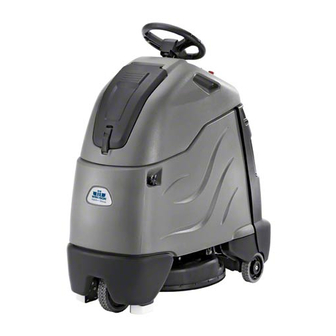
Operation How This Machine Works The function of the operator control system is to control The Chariot® iGloss 20 is a battery powered, self- the direction and speed of the machine. The directional propelled, hard floor burnisher intended for commercial control system consists of the direction control drive use. -
Page 13: Components
Operation Components 6. Bag Enclosure 7. Bag Enclosure Cover 1. Drive Control 8. Burnisher Deck 2. Burnisher Controls 9. Rear Cover 3. Control Console 4. Pedal Platform 5. Lower Body 86356230 Chariot iGloss... - Page 14 Operation Components 1. Key Switch 2. Emergency Stop/Brake Switch 3. Directional Control / Drive Reset Switch 4. Throttle Pedal 5. Horn Button 6. Steering Wheel 7. Speed Control/Function Select 8. Battery Discharge Indicator 9. Hour Meter 10. Operator Presence Switch 11.
- Page 15 Operation 1. KEY SWITCH Controls the power for machine functions. To turn the machine power on, rotate key clockwise. To turn the machine off, rotate key counterclockwise. When the key is turned on the battery symbol will flash once and stay on continuously. 2.
- Page 16 Operation 4. THROTTLE PEDAL Controls the speed of the vehicle within the speed control setting selected. Pressing the pedal causes the machine to travel in the direction selected by the Directional Control Switch. To increase speed, increase pressure on the pedal. To decrease speed, decrease pressure on the pedal.
- Page 17 Operation 8. BATTERY DISCHARGE INDICATOR Indicates the charge level of the batteries. The indicator will be illuminated if the batteries have a sufficient charge. A slow, continuous flash indicates the batteries require charging. The Battery Lockout function will activate when the batteries are low. Once active, the LED status indicator will begin to flash slowly and the controller will inhibit the burnisher motor.
- Page 18 Operation 1. FUNCTION MODE SWITCH The first two positions are for transport only. See drive controls section. B1 - Light burnishing This mode is used for light burnishing. In this mode the machine will propel at fast speed. The ‘floating’ burnisher deck is in the down position.
- Page 19 Notes: 86356230 Chariot iGloss...
-
Page 20: Pre-Run Machine Inspection
Operation Machine Operation Pre-Run Machine Inspection Do a pre-run inspection to find possible problems that could cause poor performance or lost time from break- down. Follow the same procedure each time to avoid missing steps. NOTE: See maintenance section for pre-run machine inspection checklist items. -
Page 21: Operating The Machine
Operation Operating the Machine Normal Burnishing When operating the machine around people, pay close Plan the burnishing pattern in advance. The longest attention for unexpected movement. Use extra caution track is around the perimeter of the area to be around children. burnished. -
Page 22: Maintenance
Maintenance Service Schedule BEFORE EACH AFTER EACH MAINTENANCE WORK PERIOD WORK PERIOD Check water level of batteries after charging; add distilled water if necessary. (Wet cell only) Visually check for damaged or worn tires. Check brush or pad for proper installation. Check vacuum hose connections. - Page 23 Maintenance 1. Cover Retainer Latch 2. Rear Cover 3. Battery Connector-Machine 4. Batteries 5. Battery Tray 86356230 Chariot iGloss...
- Page 24 Maintenance Batteries (Wet Cell) The batteries provide the power to operate the machine. The batteries require regular maintenance to keep them operating at peak efficiency. The machine batteries will hold their charge for long periods of time, but they can only be charged a certain number of times.
-
Page 25: Battery Maintenance
Maintenance Battery Maintenance 1. When cleaning the batteries, use a solution of baking soda and water. Do not allow the cleaning When servicing machine, avoid contact with fluid to enter the battery cells, electrolyte will be battery acid. neutralized. 2. Maintain the proper electrolyte level in each battery cell. -
Page 26: Checking Battery Specific Gravity
Maintenance Checking Battery Specific Gravity Use a hydrometer to check the battery specific gravity. CHECKING GRAVITY a. Hydrometer Battery b. Battery NOTE: Do not take readings immediately after adding distilled water, if the water and acid are not thoroughly mixed, the reading may not be accurate. Check the hydrometer readings against this chart. -
Page 27: Charging Batteries
Maintenance Use a 36 volt, 20 amp maximum output DC charger Charging Batteries which will automatically shut off when the batteries are fully charged. 1. Stop the machine in a clean, well ventilated area When servicing machine, avoid contact with next to the charger. -
Page 28: Changing Batteries
Maintenance 5. Replace the battery caps, and leave them in place 4. Disconnect main positive lead and secure cable while charging. terminals away from batteries. 6. Unplug the battery connector from the machine. 5. Loosen both terminals on each jumper cable and remove one at a time. -
Page 29: Battery Charger Programming
Maintenance Battery Charger Programming Check Default Charge Algorithm 1. Enter Algorithm Display Mode (as above). NOTE: For machines equipped with optional on- board charger. When replacing batteries, charger 2. While Algorithm Number is displayed (for 11 programming changes may be required. If replacing seconds), touch positive lead to the battery pack batteries with same type, (e.g. - Page 30 Maintenance Burnishing Deck Dust Collection 1. Burnisher Motor 5. Dust Bag 2. Skirt 3. Pad Driver/Pad 4. Pad Rotation Lock Lever 86356230 Chariot iGloss...
-
Page 31: Burnishing Pad
Maintenance • Rotate firmly counterclockwise. Pad driver will Burnishing Pad disconnect from motor hub. Many types of pads are available for floor burnishing. • Release Pad Rotation Lock lever. Select a pad type based on floor type and floor finish for best results. -
Page 32: Burnisher Motor Carbon Brush Ring Replacement
Maintenance 6. Prepare new brush assembly for use by inserting Burnisher Motor Replacement individual brush springs into brush guides. Check 1. Remove the pad driver assembly. each brush to ensure proper movement after installing springs. 2. Lower the burnisher deck using the Function Mode Switch. -
Page 33: Circuit Breakers
Maintenance CIRCUIT BREAKERS 100A CIRCUIT BREAKER Circuit Breakers Circuit breakers interrupt the flow of power in the event of an electrical overload. When a circuit breaker is tripped, reset it by pressing the exposed button. If a circuit breaker continues to trip, the cause of the electrical overload should be found and corrected. -
Page 34: Body Assembly Removal
Maintenance Body Assembly Removal Drive Unit Removal In order to access the frame or drive components, the 1. Remove tank assembly. entire tank/console cover assembly can be removed as 2. Pull the brake and drive electrical connectors off of a single unit. their support plate. - Page 35 Notes: 86356230 Chariot iGloss...
-
Page 36: Vacuum - Optional
Maintenance Vacuum - Optional 1. Vacuum Motor 2. Vacuum Filter 86356230 Chariot iGloss... - Page 37 Maintenance Vacuum Motor Carbon Brush Replacement Vacuum Motor Carbon Brushes FOR SAFETY: before leaving or servicing machine, End Cap stop on a level surface, turn off machine and disconnect power. To Repair or Replace Vacuum Motor Carbon Brushes 1. Remove four (4) screws from top of control panel. 2.
-
Page 38: Drive Motor
Maintenance Drive Motor Drive Chain Tension The drive chain should deflect about 1/4 inch on either Drive Motor Carbon Brush Replacement side of the loop when the opposite side is tight. To adjust chain tension: 1. Remove bumper. Do not use a pressure washer to clean around the motors. -
Page 39: Inclines
Maintenance Drive gear engaged Inclines Machine can be driven. When navigating an incline the machine may come to a stop. Turn the machine off. Wait 5 minutes and start the Rotate lever firmly in direction of arrow. machine and proceed up the incline. Overheating may occur if you do not wait the full 5 minutes. -
Page 40: Machine Tie-Downs
Maintenance Preparation for Loading/Unloading Trailer Burnisher Deck must be in the up position before loading. When transporting the machine on a trailer or in a truck, in addition to using tie-downs, be sure to block the tires to prevent the machine from rolling. Machine Tie-Downs There are two tie points located in front of the rear wheels on the frame, and a Tie-down wrap point on the back panel. -
Page 41: Troubleshooting
Maintenance Troubleshooting PROBLEM CAUSE SOLUTION No machine function Console lid is open Close console lid No power to machine Battery disconnected Check all battery cable connections Emergency shut-off activated Reset Battery cables corroded Clean connections Faulty key switch Replace switch Batteries not plugged in Plug batteries in On Board charger plugged in... - Page 42 Maintenance PROBLEM CAUSE SOLUTION Vacuum motor does not run, or Faulty vacuum circuit or switch Check wires & connections runs slowly Worn vacuum motor brushes Replace brushes, check commutator Vacuum circuit breaker tripped Reset circuit breaker Poor burnishing performance Debris caught in pad Remove debris or change pad Worn pad Replace pad or flip pad...
-
Page 43: 86356230 Chariot Igloss
Maintenance Battery Discharge Indicator Troubleshooting The battery indicator flashes when a problem occurs. The table below list solutions for the indicated problems. Number of Problem Solution flashes The battery needs charging, there is a bad connection to If the connections are good, try the battery or dependent on the programming, may charging the battery. -
Page 44: 86356230 Chariot Igloss
Notes: 86356230 Chariot iGloss... -
Page 45: Parts
Parts PARTS 86356230 Chariot iGloss... -
Page 46: Body Brace
Body Brace ORIENT BREAKER AS SHOWN (SEE DETAIL A) (SEE DETAIL A) SEE WIRING DIAGRAM FOR P/NS DETAIL A 86356230 Chariot iGloss... - Page 47 Body Brace SERIAL NO. PART NO. QTY DESCRIPTION NOTES FROM 86273820 SCREW 1/4-20 X 1.25 HHCS 86010630 WASHER 1/4 ID X 5/8 OD SS 86340020 COVER, PANEL MNT BREAKER 86275120 SCR, 1/4-20 X.75 PPHMS PHIL 86340030 BREAKER, 100A CIRCUIT 86277500 SCR,1/4-20 X 5/8 CARR SS 86229770 BLOCK, SHUNT MOUNT...
-
Page 48: Body Lower
Body Lower 86356230 Chariot iGloss... - Page 49 Body Lower SERIAL NO. PART NO. QTY DESCRIPTION NOTES FROM 86273980 SCREW 10-32 X 3/4 PPHMS 86010650 SP WASHER #10 X 9/16 OD 86354990 CLAMP, .75 DIA, FLEX LOOP, NYLON 86010670 WASHER 5/16 FLAT SS 86279130 WASHER 5/16 SPLIT LOCK PLTD 86276780 SCR, 5/16-18 X 3/4 HHCS SS 86354570...
-
Page 50: Body Lower Mounting
Body Lower Mounting 86356230 Chariot iGloss... - Page 51 Body Lower Mounting SERIAL NO. PART NO. QTY DESCRIPTION NOTES FROM 86279630 WASHER, .344IDX1.13ODX.09T PLT 86006760 SCREW 5/16-18 X 3/4HHCSGR5PLTDL 86275180 SCR, 5/16-18 X 1/2 HHCS GR5 NP 86356230 Chariot iGloss...
-
Page 52: Bumper
Bumper 86356230 Chariot iGloss... - Page 53 Bumper SERIAL NO. PART NO. QTY DESCRIPTION NOTES FROM 86318180 BUMPER, TRIM, GRAY 86276980 SCREW 5/16-18 X 2 HHCS SS 86010670 WASHER 5/16 FLAT SS 86276070 SCR, 5/16-18 X 3/4 CARRIAGE SS 86270830 NUT 5/16-18 HEX NYLOCK SS 86323950 PAD, TIP 86327510 SCR, KA50X16, PT OHS, WN1412, A2 SS 86271840...
-
Page 54: Burnishing Deck
Burnishing Deck WIRE HARNESS A TORQUE 18 FT-LBS B TORQUE 65 IN-LBS 86356230 Chariot iGloss... - Page 55 Burnishing Deck SERIAL NO. PART NO. QTY DESCRIPTION NOTES FROM 86354980 MOTOR, 36VDC 3 HP 2000RPM 86348010 BRUSH SET, BURNISHER MOTOR 86286850 KEY, 3/16 SQ X 1.5” LONG 86353470 BRACKET, MOTOR LIFT 86352910 SHROUD, OUTER 86353780 BRUSH, FLEXIBLE STRIP, 72" LONG 86352900 SHROUD, INNER 86353750...
-
Page 56: Burnishing Deck Mounting
Burnishing Deck Mounting 14 13 A TORQUE 8 FT-LBS 6 7 8 86356230 Chariot iGloss... - Page 57 Burnishing Deck Mounting SERIAL NO. PART NO. QTY DESCRIPTION NOTES FROM 86353790 BRACKET, LINKAGE ARM 86277030 SCR, 5/16-18X1.25 CARRIAGE SS 86228840 BEARING FLANGED.314IDX.502OD 86259410 WASHER THRUST.51 ID X1ODX.063 86279350 WASHER, WAVE 1/2ID X3/4D X.125 86259420 WASHER, THRUST .51ID X 1 ODBRO 86010670 WASHER 5/16 FLAT SS 86270830...
-
Page 58: Burnishing Deck Lift
Burnishing Deck Lift 86356230 Chariot iGloss... - Page 59 Burnishing Deck Lift SERIAL NO. PART NO. QTY DESCRIPTION NOTES FROM 86328040 PIN, CLEVIS, 1/4 X 2.0 L 86354750 WASHER, 1.00X.264X.070THK, NYL, BLK 86320880 ACT, 36VDC, 3.0" STK, 8.74 LNG 86008650 COTTER 1/4" RING 86342240 SPACER, .81 X 1.06 X .125 86356230 Chariot iGloss...
-
Page 60: Pad Driver
Pad Driver A TORQUE 6 IN-LBS B TORQUE 20-22 IN-LBS C TORQUE 34-36 IN-LBS 86356230 Chariot iGloss... - Page 61 Pad Driver SERIAL NO. PART NO. QTY DESCRIPTION NOTES FROM 86352460 HUB, PAD DRIVER 86355650 GROMMET, .188ID x .438OD x .188T 86173140 SCR, KA40X16,PT OVAL,WN1412,PL 86355620 RETAINER, PAD CENTER LOCK 86173330 WASHER, M5, FLAT, ISO7093, SS 86327910 SCR, KA50X25, PT OHS, WN1412, PLTD 86355610 PAD DRIVER, FACE 20"...
-
Page 62: Control Panel
Control Panel A TORQUE 45-55 IN-LBS ACTIVE MODELS ONLY 86356230 Chariot iGloss... - Page 63 Control Panel SERIAL NO. PART NO. QTY DESCRIPTION NOTES FROM 86275260 SCR, 4-40 X 1/2 PPHMS 86326390 CONN, 8MM PITCH, 10 POSN 86352490 PANEL, CONTROL iGLOSS 20 86255910 STANDOFF, 1/4-20 X 1.0 HEX INS 86006850 SCR, 1/4-20 X 1.25 SSSCU 86005710 NUT, 1/4-20 HEX W/STAR 86279450...
-
Page 64: Control Panel
Control Panel ACTIVE MODELS ONLY 86356230 Chariot iGloss... - Page 65 Control Panel SERIAL NO. PART NO. QTY DESCRIPTION NOTES FROM 86332510 BOOT, SEAL PUSH BUTTON 11MM ACTIVE MODEL ONLY 86001260 BOOT, CB 3/8-32 UNS 86348640 LED, BAG FULL INDICATOR 86348960 LED, BATTERY INDICATOR 53217380 KNOB, SELECTION 63130140 SPRING ELEMENT 86295200 ASM, BUTTON, BLACK, W/BEZEL 86313950 SWITCH, SPDT 3 POSN MOM, ARROW...
-
Page 66: Charger-Optional
Charger-Optional 86356230 Chariot iGloss... - Page 67 Charger-Optional SERIAL NO. PART NO. QTY DESCRIPTION NOTES FROM 86273780 SCR, 1/4-20 X 3/4 HHCS SS NP 86010780 WASHER 1/4 SPLIT LOCK PLTD 86010630 WASHER 1/4 ID X 5/8 OD SS 86234390 SP CORD ASM, 16/3 SJTW X 2M IEC 86353300 CHARGER, 36V 21A, OBC, 4 PROFILE 86344430...
-
Page 68: Hinge
Hinge BLACK WIRE FROM CONTROL PANEL 86356230 Chariot iGloss... - Page 69 Hinge SERIAL NO. PART NO. QTY DESCRIPTION NOTES FROM 86276780 SCR, 5/16-18 X 3/4 HHCS SS 86010670 WASHER 5/16 FLAT SS 86328860 NUT, 5/16 PUSH-LOCK, PLTD 86270860 NUT, 10-24 U-TYPE SPEED 86277110 SCR, 10-24 X 3/4 PPHMS SS 86327680 SWITCH, INTERLOCK 86326320 BRACKET, HINGE UPPER 86228990...
-
Page 70: Decals
Decals 86356230 Chariot iGloss... - Page 71 Decals SERIAL NO. PART NO. QTY DESCRIPTION NOTES FROM 86004970 LABEL WINDSOR LOGO DOMED 86353580 LABEL, PANEL, iGLOSS 20, DLX ACTIVE MODELS 86357750 LABEL, PANEL iGLOSS 20 PASSIVE MODELS 86354330 LABEL, iGLOSS 20 LEFT 86354340 LABEL, iGLOSS 20 RIGHT 86363810...
-
Page 72: Drive-Chain
Drive-Chain A TORQUE 6-7 FT-LBS 86356230 Chariot iGloss... - Page 73 Drive-Chain SERIAL NO. PART NO. QTY DESCRIPTION NOTES FROM 86330720 CHAIN TENSIONER 86329350 NUT, 1/4-20 X 7/8 HEX COUPLING SS 86328050 WASHER, SHOULDER.48ID X 1.25OD 86005810 NUT, 1/4-20 HEX NYLOCK SS 86273100 SCR, 1/4-20X2-1/4 HXHD CAP 86322060 COLLAR, 12MM ID 86322050 SPROCKET, STEERING, 14T 86322040...
-
Page 74: Drive-Lower
Drive-Lower NOTE: TERMINAL HARDWARE INSTALLED, 2 LOCATIONS A TORQUE 15/18 FT/LBS B TORQUE 120 IN/LBS C TORQUE 15 FT/LBS D TORQUE 60 IN/LBS E TORQUE 100 IN/OZ AFTER 86356230 Chariot iGloss... - Page 75 Drive-Lower SERIAL NO. PART NO. QTY DESCRIPTION NOTES FROM 86326710 KEY, 5 X 5 X 16 86321670 WASHER, WHEEL SPACER 86319810 AXLE, DRIVE WHEEL 86319670 SLEEVE, BEARING 86364010 MOTOR, TRACTION (4*) 86331990 BRUSH SET, SMALL RIDER DRIVE MTR NOT SHOWN 98408960 BRAKE REPLACEMENT SMALL STAND ON NOT SHOWN...
-
Page 76: Drive Mounting
Drive Mounting 86356230 Chariot iGloss... - Page 77 Drive Mounting SERIAL NO. PART NO. QTY DESCRIPTION NOTES FROM 86326080 BRACKET, LINKAGE MOUNT, RIGHT 86319730 BRACKET, LINKAGE MOUNT, LEFT 86331630 BRACKET, ROLLER GUIDE 86010670 WASHER, 5/16 X 3/4 SS 86276690 SCR, 5/16-18 X 1.75 CARR SS 86276070 SCR, 5/16-18 X 3/4 CARRIAGE SS 86270830 NUT, 5/16-18 HEX NYLOCK SS 86274760...
-
Page 78: Console - Bag Enclosure
Console - Bag Enclosure 86356230 Chariot iGloss... - Page 79 Console - Bag Enclosure SERIAL NO. PART NO. QTY DESCRIPTION NOTES FROM 86173140 SCR, KA40X16,PT OVAL,WN1412,PL 86161800 CATCH CONCEALED KEEPER 86353230 COVER, BAG ENCLOSURE 86353650 SHAFT, .25 X 7.3, SS 86275810 SCR, 10-32 X 1 PPHMS BLK 86010650 SP WASHER #10 X 9/16 OD 86005640 NUT 10-32 HEX NYLOCK 86353170...
-
Page 80: Frame & Rear Wheels
Frame & Rear Wheels 86356230 Chariot iGloss... - Page 81 Frame & Rear Wheels SERIALNO. PART NO. QTY DESCRIPTION NOTES FROM 86326260 BRACKET, FRAME LEFT 86326250 BRACKET, FRAME RIGHT 86356380 FRAME ASM IGLOSS 20 INCLUDES ITEM 8 & 9 SPACER, FLG .887ID X 1.055D X 86326220 .345LG 86318030 AXLE, 20MM X 562 MM 86318020 WHEEL, PU 150MM X 40MM 86223470...
-
Page 82: Pedal Platform
Pedal Platform 86356230 Chariot iGloss... -
Page 83: Pedal Platform
Pedal Platform SERIAL NO. PART NO. QTY DESCRIPTION NOTES FROM 86007110 SWITCH, 25A SPST 125-250V SNAP SCR, KA50X10, PT OHS, WN1412, 86172980 PLTD 86264930 CABLE TIE, 3.5" UL/CS 86326150 BRKT, LINEAR POT 86326140 PIN, DOWEL .25 X 2.75, STEEL 86318010 PEDAL, HEEL 86318000 PEDAL, ACCELERATOR... -
Page 84: Pedal Platform Mounting
Pedal Platform Mounting 86356230 Chariot iGloss... - Page 85 Pedal Platform Mounting SERIAL NO. PART NO. DESCRIPTION NOTES FROM 86327510 SCR, KA50 X 16, WN1412 A2 SS 86198440 CLAMP, 1/4 PLASTIC CABLE 86327910 SCR, KA50X25, PT OHS, WN1412, PLTD 86173330 WASHER, M5, FLAT, ISO7093, SS 86198470 CLAMP, 9/16 DIA NYLON 86356230 Chariot iGloss...
-
Page 86: Steering
Steering 86356230 Chariot iGloss... - Page 87 Steering SERIAL NO. PART NO. QTY DESCRIPTION NOTES FROM 86259610 WHEEL STEERING 40 SPLINE HUB 86271610 NUT 5/8-18 HEX NYLOCK THN 86279420 WASHER,.75IDX1.25ODX.125THK NY 86339320 ASM SHAFT, STEERING, CS20 86234810 COVER, STEERING WHEEL 86356230 Chariot iGloss...
-
Page 88: Vacuum-Optional
Vacuum-Optional 86356230 Chariot iGloss... - Page 89 Vacuum-Optional SERIAL NO. PART NO. QTY DESCRIPTION NOTES FROM 86273920 SCREW 1/4-20 X 1.75 PPHMS 86010630 WASHER 1/4 ID X 5/8 OD SS 86353290 BRKT, VAC MOTOR 86312920 GASKET, VAC MOTOR 86012210 VAC MOTOR, 36VDC 2ST TD 86264940 CABLE TIE, 11.38" UL/CSA 86327500 MOUNT, VIBRATION 86002400...
-
Page 90: Wiring-Battery
Wiring-Battery 86356230 Chariot iGloss... - Page 91 Wiring-Battery SERIAL NO. PART NO. QTY DESCRIPTION NOTES FROM 86329720 BATT, CBL, ASM, JUMPER 86356120 CABLE, ASM, BATTERY 86228400 BATTERY, 12V, 130AH 86328630 BATTERY, 12V 114A/H AGM NOT SHOWN 86283410 BATTERY, 12V, 225AH (J185H-AC) NOT SHOWN 86228430 BATTERY, 12V AGM 234AH NOT SHOWN REQD.
-
Page 92: Wiring Diagram 1
Wiring Diagram 1 86356230 Chariot iGloss... -
Page 93: Wiring Diagram 1
Wiring Diagram 1 SERIAL NO. PART NO. QTY DESCRIPTION NOTES FROM 86354410 HARNESS, PANEL IGLOSS20 HARNESS, IGLOSS20 OPERATOR 86356360 PLATFORM 86354380 HARNESS, ROTARY SWITCH 86344450 HARNESS, MAIN ACTUATOR HARNESS, IGLOSS20 MAIN POT AND 86356350 BRAKE 86356370 HARNESS, IGLOSS20 MAIN CHARGER 86356340 HARNESS, IGLOSS20 MAIN TRACTION 86354390... -
Page 94: Wiring Diagram 2
Wiring Diagram 2 86356230 Chariot iGloss... -
Page 95: Wiring Diagram 2
Wiring Diagram 2 SERIAL NO. PART NO. QTY DESCRIPTION NOTES FROM 86352310 HARNESS, I-DRIVE GND DESCRIPTION DRIVE CONTROL RELAY BOARD PROCESSOR CIRCUIT BREAKER-DRIVE CONTROL CIRCUIT BREAKER-VACUUM MOTOR - OPTIONAL CIRCUIT BREAKER-BRUSH G1-G3 BATTERY 12V SIGNAL LAMPS REVERSE DIRECTION SIGNAL LAMPS DIRECTION FORWARD HORN LED-BATT. -
Page 96: Wiring Diagram 3
Wiring Diagram 3 86356230 Chariot iGloss... -
Page 97: Wiring Diagram 3
Wiring Diagram 3 DESCRIPTION DRIVE CONTROL RELAY BOARD PROCESSOR CIRCUIT BREAKER-DRIVE CONTROL CIRCUIT BREAKER-VACUUM MOTOR - OPTIONAL CIRCUIT BREAKER-BRUSH G1-G3 BATTERY 12V SIGNAL LAMPS REVERSE DIRECTION SIGNAL LAMPS DIRECTION FORWARD HORN LED-BATT. RELAYS-REVERSE DIRECTION RELAYS DIRECTION FORWARD RELAYS BRUSH MOTOR RELAY VACUUM MOTOR - OPTIONAL RELAYS ACTUATOR RELAYS MAIN... -
Page 98: Wiring Diagram 4
Wiring Diagram 4 86356230 Chariot iGloss... - Page 99 Wiring Diagram 4 DESCRIPTION DRIVE CONTROL RELAY BOARD PROCESSOR CIRCUIT BREAKER-DRIVE CONTROL CIRCUIT BREAKER-VACUUM MOTOR - OPTIONAL CIRCUIT BREAKER-BRUSH G1-G3 BATTERY 12V SIGNAL LAMPS REVERSE DIRECTION SIGNAL LAMPS DIRECTION FORWARD HORN LED-BATT. RELAYS-REVERSE DIRECTION RELAYS DIRECTION FORWARD RELAYS BRUSH MOTOR RELAY VACUUM MOTOR - OPTIONAL RELAYS ACTUATOR RELAYS MAIN...
-
Page 100: Wiring Diagram 5
Wiring Diagram 5 86356230 Chariot iGloss... -
Page 101: Wiring Diagram 5
Wiring Diagram 5 DESCRIPTION DRIVE CONTROL RELAY BOARD PROCESSOR CIRCUIT BREAKER-DRIVE CONTROL CIRCUIT BREAKER-VACUUM MOTOR - OPTIONAL CIRCUIT BREAKER-BRUSH G1-G3 BATTERY 12V SIGNAL LAMPS REVERSE DIRECTION SIGNAL LAMPS DIRECTION FORWARD HORN LED-BATT. RELAYS-REVERSE DIRECTION RELAYS DIRECTION FORWARD RELAYS BRUSH MOTOR RELAY VACUUM MOTOR - OPTIONAL RELAYS ACTUATOR RELAYS MAIN... -
Page 102: Wiring Diagram 6
Wiring Diagram 6 86356230 Chariot iGloss... - Page 103 Wiring Diagram 6 DESCRIPTION DRIVE CONTROL RELAY BOARD PROCESSOR CIRCUIT BREAKER-DRIVE CONTROL CIRCUIT BREAKER-VACUUM MOTOR - OPTIONAL CIRCUIT BREAKER-BRUSH G1-G3 BATTERY 12V SIGNAL LAMPS REVERSE DIRECTION SIGNAL LAMPS DIRECTION FORWARD HORN LED-BATT. RELAYS-REVERSE DIRECTION RELAYS DIRECTION FORWARD RELAYS BRUSH MOTOR RELAY VACUUM MOTOR - OPTIONAL RELAYS ACTUATOR RELAYS MAIN...
-
Page 104: Wiring Diagram 7
Wiring Diagram 7 86356230 Chariot iGloss... - Page 105 Wiring Diagram 7 DESCRIPTION DRIVE CONTROL RELAY BOARD PROCESSOR CIRCUIT BREAKER-DRIVE CONTROL CIRCUIT BREAKER-VACUUM MOTOR - OPTIONAL CIRCUIT BREAKER-BRUSH G1-G3 BATTERY 12V SIGNAL LAMPS REVERSE DIRECTION SIGNAL LAMPS DIRECTION FORWARD HORN LED-BATT. RELAYS-REVERSE DIRECTION RELAYS DIRECTION FORWARD RELAYS BRUSH MOTOR RELAY VACUUM MOTOR - OPTIONAL RELAYS ACTUATOR RELAYS MAIN...
-
Page 106: Wiring Diagram 8
Wiring Diagram 8 86356230 Chariot iGloss... - Page 107 Wiring Diagram 8 DESCRIPTION DRIVE CONTROL RELAY BOARD PROCESSOR CIRCUIT BREAKER-DRIVE CONTROL CIRCUIT BREAKER-VACUUM MOTOR - OPTIONAL CIRCUIT BREAKER-BRUSH G1-G3 BATTERY 12V SIGNAL LAMPS REVERSE DIRECTION SIGNAL LAMPS DIRECTION FORWARD HORN LED-BATT. RELAYS-REVERSE DIRECTION RELAYS DIRECTION FORWARD RELAYS BRUSH MOTOR RELAY VACUUM MOTOR - OPTIONAL RELAYS ACTUATOR RELAYS MAIN...
-
Page 108: Suggested Spare Parts
86353680 BREAKER, 1.5A, CARLING MAGNETIC 86316160 BREAKER, 18A, 250VAC, 32VDC 86353780 BRUSH, FLEXIBLE STRIP, 72" LONG 86348010 BRUSH SET, BURNISHER MOTOR 86135310 BRUSH SET, 24/36V VAC, WINDSOR 86232780 CHAIN MASTERLINK 12.7MM 86284790 FILTER BAG (10 PACK) 86327830 GASKET,.188X.31X41.0 86354630 GASKET, BAG MOUNT 86353660 GASKET, BAG COVER, 43.6"... - Page 109 Serial Numbers REF. NO MODEL: SERIAL # 10020350000012, 10020360000016 10020350000012, 10020360000013 10020350000014, 10020360000017 10020310000033, 10020320000009, 10020330000036, 10020340000007, 10020350000060, 10020360000075 10020310000068, 10020320000015, 10020330000040, 10020340000010, 10020350000064, 10020360000079 86356230 Chariot iGloss...
Need help?
Do you have a question about the Chariot 2 CBPS20 and is the answer not in the manual?
Questions and answers