Table of Contents
Advertisement
Quick Links
STEREO DVD CASETTE DECK RECEIVER
XV-EV1000
XV-EV700
THIS MANUAL IS APPLICABLE TO THE FOLLOWING MODEL(S) AND TYPE(S).
Model
Type
XV-EV1000
DLXJ/NC
XV-EV700
DLXJ/NC
For details, refer to "Important Check Points for good servicing".
PIONEER CORPORATION
PIONEER ELECTRONICS (USA) INC. P.O. Box 1760, Long Beach, CA 90801-1760, U.S.A.
PIONEER EUROPE NV Haven 1087, Keetberglaan 1, 9120 Melsele, Belgium
PIONEER ELECTRONICS ASIACENTRE PTE. LTD. 253 Alexandra Road, #04-01, Singapore 159936
PIONEER CORPORATION 2005
Power Requirement
AC110-127V/220-230V/240V
AC110-127V/220-230V/240V
4-1, Meguro 1-chome, Meguro-ku, Tokyo 153-8654, Japan
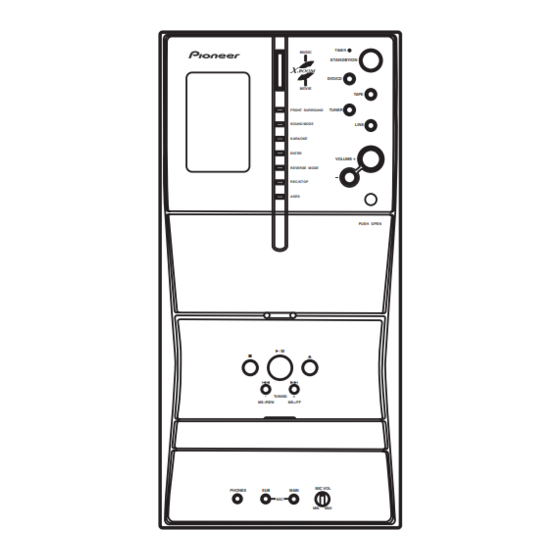
MUSIC
TIMER
STANDBY/ON
DVD/CD
MOVIE
TAPE
FRONT SURROUND
TUNER
SOUND MODE
LINE
KARAOKE
ENTER
VOLUME
REVERSE MODE
REC/STOP
ASES
PUSH OPEN
-
TUNING
+
MS-/REW
MS+/FF
MIC VOL
PHONES
SUB
MAIN
MIC
MIN
MAX
XV-EV1000
Regional
The voltage can be
restriction codes
converted by the
(Region No.)
following method.
3
With the voltage selector
3
With the voltage selector
ORDER NO.
RRV3189
Remarks
T-ZZK AUG. 2005 printed in Japan
Advertisement
Table of Contents
Troubleshooting

Related Manuals for Pioneer XV-EV1000


Summary of Contents for Pioneer XV-EV1000
- Page 1 PIONEER CORPORATION 4-1, Meguro 1-chome, Meguro-ku, Tokyo 153-8654, Japan PIONEER ELECTRONICS (USA) INC. P.O. Box 1760, Long Beach, CA 90801-1760, U.S.A. PIONEER EUROPE NV Haven 1087, Keetberglaan 1, 9120 Melsele, Belgium PIONEER ELECTRONICS ASIACENTRE PTE. LTD. 253 Alexandra Road, #04-01, Singapore 159936 PIONEER CORPORATION 2005 T-ZZK AUG.
-
Page 2: Safety Information
The interlock mechanism mentioned above becomes invalid in this mode. 2. When the cover is open, close viewing through the objective lens with the naked eye will cause exposure to the laser beam. ∗ : Refer to page 96. XV-EV1000... - Page 3 To protect products from damages or failures during transit, the shipping mode should be set or the shipping screws should be installed before shipment. Please be sure to follow this method especially if it is specified in this manual. XV-EV1000...
-
Page 4: Table Of Contents
7.1.9 ID NUMBER AND ID DATA SETTING ..................... 107 7.1.10 DSP TROUBLE SHOOTING ......................110 7.1.11 DISASSEMBLY..........................112 7.2 PARTS..............................122 7.2.1 IC ..............................122 7.3 EXPLANATION ............................125 7.3.1 SEQUENCE AFTER POWER ON....................125 7.3.2 PROTECTION CIRCUIT........................126 8. PANEL FACILITIES ............................131 XV-EV1000... -
Page 5: Specifications
Multi voltage model ..AC 110-127/220-230/ 240 V (switchable), 50/60 Hz Accessories • Power cord • FM Antenna (ADH7030) • Video Cord (ADG1154) (L = 1.5m) (XDE3046) Yellow • AM Loop Antenna • Dry Cell Batteries (ATB7013) • Remote Control (XXD3098) XV-EV1000... - Page 6 DVD Format/Logo Licensing Corporation • Also compatible with KODAK Picture CD This player supports the IECís Super VCD stan- dard for superior picture quality, dual soundtracks, and widescreen support. VIDEO Super Video CD (Super VCD) XV-EV1000...
-
Page 7: Exploded Views And Parts List
Dry Cell Batteries (AA/R6) VEM1031 Video Cord XDE3046 Operating Instructions (English) XRB3053 Operating Instructions (Chinese)XRC3209 Remote Control XXD3098 (2) CONTRAST TABLE XV-EV700/DLXJ/NC and XV-EV1000/DLXJ/NC are constracted the same except for the following : Mark Description XV-EV1000/DLXJ/NC XV-EV700/DLXJ/NC Getter Label XAX3539 XAX3526 Packing Case... -
Page 8: Exterior Section
2.2 EXTERIOR SECTION Refer to "2.4 FRONT PANEL SECTION". Refer to "2.3 AMP SECTION". Refer to "2.5 05 LOADER ASSY". XV-EV1000... - Page 9 Rear Panel See Contrast table (2) Push Rivet XEC3034 Mecha Barrier XEC3062 Primary Barrier XEC3063 (2) CONTRAST TABLE XV-EV700/DLXJ/NC and XV-EV1000/DLXJ/NC are constracted the same except for the following : Mark Description XV-EV1000/DLXJ/NC XV-EV700/DLXJ/NC POWER Assy XWZ4016 XWZ4018 IFAF Assy...
-
Page 10: Amp Section
Refer to Refer to "2.2 EXTERIOR "2.2EXTERIOR SECTION. " SECTION. " Refer to "2.2 EXTERIOR SECTION. " Cleaning paper GED-008 Refer to Refer to "2.2 EXTERIOR "2.2 EXTERIOR SECTION. " SECTION. " Refer to "2.4 FRONT PANEL SECTION. " XV-EV1000... - Page 11 Heat Sink XNH3038 NSP 11 Chassis Hal XNA3025 AMP Support F XNG3141 AMP Support R XNG3142 NSP 14 Spacer AEB7092 Rubber Cushion XEB3047 LEG Cushion R XEB3050 Binder ZCA-SKB90BK Screw BBZ30P060FTC Screw BBZ30P080FNI Screw BBZ40P060FTC Screw BBZ30P140FTC Screw BBZ30P300FTC XV-EV1000...
-
Page 12: Front Panel Section
2.4 FRONT PANEL SECTION Refer to "2.2 EXTERIOR SECTION. " XV-EV1000 Only Refer to Refer to "2.2 EXTERIOR "2.3 AMP SECTION. " SECTION. " Refer to "2.2 EXTERIOR SECTION. " Refer to Refer to "2.2 EXTERIOR "2.2 EXTERIOR SECTION. "... - Page 13 XMR3002 LCD Holder XMR3095 Binder ZCA-SKB90BK MIC Knob XAA3029 LCD LT Cond XAK3502 (2) CONTRAST TABLE XV-EV700/DLXJ/NC and XV-EV1000/DLXJ/NC are constracted the same except for the following : Mark Description XV-EV1000/DLXJ/NC XV-EV700/DLXJ/NC DISPLAY Assy XWZ4012 XWZ4010 FUNC. LT. Cond. XAK3514 Not used VOL.
-
Page 14: Loader Assy
JGZ17P028FTC Flexible Cable (24P) VDA2008 Screw VBA1094 Connector Assy 2P VKP2253 Tray VNL1920 Floating Rubber VEB1351 Clamp Magnet VMG1029 Belt VEB1358 Stabilizer VNE2253 Loading Base VNL1917 Float Base 04 VNL1968 Drive Cam VNL1919 Gear Pulley VNL1921 Loading Gear VNL1922 XV-EV1000... - Page 15 Rear View Daifree Daifree No. 23 No. 23 GEM1036 GEM1036 Tray Tray Concave of unevenness Concave of unevenness Inner side of a ditch Daifree GEM1036 Top View Bottom View Side of the rib Concave of unevenness Daifree Daifree GEM1036 GEM1036 XV-EV1000...
-
Page 16: Traverse Mechanism Assy-S
DLA1940 NSP 12 Stepping Screw DBA1205 Sub Guide Shaft VK1 DLA1941 Spindle Screw VK1(for Service) DBA1252 NSP 5 Joint VK1B DNK4272 Joint Spring VK1 DBK1235 Stepping Motor VK1 DXM1201 NSP 8 Mechanism Frame VK1 DNK4160 Precision Screw VK1 DBA1209 XV-EV1000... -
Page 17: Deck Mechanism Assy
Part No. Cable Assy XDE3066 Main Belt FF20B-13A 11P F.F.C/60V XDD3184 F/R Belt FF19S-31 Plate HD Blk F513-926 Roller Pinch Blk R F514-133 Roller Pinch Blk L F514-134 Clutch Assy Blk F522-063 Motor Main Blk F525-394 PCB Control Blk F567-747 XV-EV1000... -
Page 18: Block Diagram And Schematic Diagram
DSPINR DSPINR Y(Lch) Y(Lch) HA17558AF BUFFER X(Rch) X(Rch) 4 11 SLO/SRO SLO/SRO PASSIVE IC8111 PBL/ PBL/ HA17558AF IC8701 HA17558AF DSP ASSY TAPE DECK MECHA MECHA XYM3019 ATTENUATOR - 10dB - 6dB CN2301 (4P) DECKL/ DECKL/ IFAF ASSY DECKR DECKR XV-EV1000... -
Page 19: Display Assy
SL/SR IC3057 SL/SR SL/SR HA17558AF SL/SR SL/SR CN8303 CN3051 JA3301 CN3011 CN3021 CN3001 POWER AMP POWER AMP (27P) (12P) (27P) (17P) (23P) (23P) MODULE MODULE J3032 CN3012 (13P) (13P) TRADE ASSY POWER ASSY DECKL/ DECKL/ DECKR DECKR LINE CN8401 XV-EV1000... -
Page 20: Overall Wiring Connection Diagram And Loab Assy
3.2 OVERALL WIRING CONNECTION DIAGRAM and LOAB ASSY ASSY XWK3202 1/4- 17P FFC XDD3180 D20PYY1315E POWER ASSY XV-EV1000: XWZ4016 JA3301 XV-EV700: XWZ4018 XKE3037 MICSW MICSW HP/MIC ASSY GNDA GNDA XWZ4014 VA+12V VA+12V ECHOVOL ECHOVOL J5401 CN5105 51048-0500 52147-0510 FLASH E/D... - Page 21 11P FFC XXA3037 RECR RECR 52045-1145 CN5503 DVD MODULE IFAF ASSY FOCS RTN FOCS RTN TRKUP FOCS DRV FOCS DRV TRKUP XV-EV1000: XWZ4003 TRKG RTN TRKG RTN DVDMUTE DVDMUTE TRKG DRV TRKG DRV VDET VDET XV-EV700: XWZ4006 VSHF VSHF GNDD...
-
Page 22: Dvdm Assy (1/2)
: TRACKING SERVO LOOP LINE : STEPPING SERVO LOOP LINE (C/V) : VIDEO SIGNAL ROUTE (R/Cr) : VIDEO SIGNAL ROUTE(R/Cr) (G/Y) : VIDEO SIGNAL ROUTE(G/Y) (B/Cb) : VIDEO SIGNAL ROUTE(B/Cb) (S_Y) : S VIDEO SIGNAL ROUTE (S_C) : S VIDEO SIGNAL ROUTE XV-EV1000... - Page 23 DVDM ASSY (AWM7964) XV-EV1000...
-
Page 24: Dvdm Assy (2/2)
3.4 DVDM ASSY (2/2) DVDM ASSY (AWM7964) XV-EV1000... - Page 25 (R/Cr) (B/Cb) (R/Cr) : AUDIO SIGNAL ROUTE (C/V) : VIDEO SIGNAL ROUTE (R/Cr) : VIDEO SIGNAL ROUTE(R/Cr) (G/Y) : VIDEO SIGNAL ROUTE(G/Y) (B/Cb) : VIDEO SIGNAL ROUTE(B/Cb) (S_Y) : S VIDEO SIGNAL ROUTE (S_C) : S VIDEO SIGNAL ROUTE XV-EV1000...
-
Page 26: Ifaf Assy (1/4)
3.5 IFAF ASSY (1/4) XV-EV1000 XV-EV700 2/4, 3/4 CN901 XV-EV1000... - Page 27 IFAF ASSY XV-EV1000 XWZ4003 XV-EV700 XWZ4006 2/4, 3/4 : AUDIO SIGNAL ROUTE : AUDIO SIGNAL ROUTE (TXL) : AUDIO SIGNAL ROUTE (TXR) XV-EV1000...
-
Page 28: Ifaf Assy (2/4)
DSPINL VA+12 VE+56 Q8113 Q8111 2SC4081(QR) 2SC4081(QR) R8124 R8115 R8119 VA-12 VA-12 R8125 Q8114 2SC4081(QR) R8116 Q8112 2SC4081(QR) IC8111 Q8115 R8120 HA17558AF RT1P241M Q8116 (2/2) C8122 R8112 10/50 C8116 RT1P241M 1.5k 10/50 DSPINR 1/4, VA-5 U-COM (I/O) DSPA DSPA XV-EV1000... - Page 29 NOTES IFAF ASSY( ALL CAPACITORS ARE IN µF XV-EV1000 XWZ4003 ALL DIODE UNLESS OTHERWISE SPECIFIED XV-EV700 XWZ4006 CH : CCSRCH (OTHER : CKSR :MA111 TY : CFTYA :1SS133 J5401 AL : CEAL (OTHER : CEAT) ALL RESISTORS ARE IN RD1/4PU***J...
-
Page 30: Ifaf Assy (3/4)
3.7 IFAF ASSY (3/4) XV-EV1000... - Page 31 IFAF ASSY CN902 XV-EV1000 XWZ4003 XV-EV700 XWZ4006 : AUDIO SIGNAL ROUTE (Front R ch) (FR) : AUDIO SIGNAL ROUTE (Front L ch) (FL) : AUDIO SIGNAL ROUTE (Center ch) (SR) : AUDIO SIGNAL ROUTE (Surround Rch) CN3051 (SL) : AUDIO SIGNAL ROUTE(Surround Lch)
-
Page 32: Ifaf Assy (4/4)
RTD1082 Q2801 2SC1815(YGR) L2802 NOTES VREF 0.12mH LFA121J ALL CAPACITORS ARE IN µF UNLESS OTHERWISE SPECIFIED CH:CCSRCH*** C2809 YF:CKSRYF*** 150p/500 R2811 R2809 OTHER:CKSRYB*** Q2805 Q2806 2SC1815(YGR) M:CQMA*** 2SC2240 (Y/GR) R2815 HA:CQHA*** MB:CQMBA*** TS:CE*****M##-TS GNDM(TC) JQ:CEJQ***M##-* AL:CEAL***M##-* (OTHER : CEAT***M##) XV-EV1000... - Page 33 PB TEST POINT IFAF ASSY( XV-EV1000 XWZ4003 D2256 XV-EV700 XWZ4006 C2255 GNDA 1SS133-T 1/50 C2252 0.33 VA+12V R2268 IC2202(2/2) -3.7dBV HA17558AF Q2263 GNDD RT1N431M C2257 C2254 C2261 R2283 2.2/50 (TC) 4.7K R2270 4.7/50 R2267 R2269 2SD2114K R2261 R2281 D2257 R2241 3.9K...
-
Page 34: Dsp Assy
3.9 DSP ASSY DSP ASSY (AWX8588) CN951 CN5507 XV-EV1000... - Page 35 : AUDIO SIGNAL ROUTE(Surround L ch) : AUDIO SIGNAL ROUTE(DIGITAL) : AUDIO SIGNAL ROUTE(Center ch) (SW) (AD) : AUDIO SIGNAL ROUTE(Sub Woofer ch) : AUDIO DATA SIGNAL ROUTE (FL) (AD) (AD) (AD) (SL) (AD) (sw) (DVD) (DVD) CN901 CN5505 XV-EV1000...
-
Page 36: Key, Led And Display Assys
S5104 : KARAOKE S5105 : ENTER ASES ASSY S5106 : REVERSE MODE S5107 : REC STOP XWZ4023 GNDU S5108 : ASES VP+12 LED HOLDER XMR3099- W739 VP+12 LEDCN2 R5214 STBY LEDCN1 GNDLED Q5204 2SC3052(EF) Q5219 Q5220 2SC3052(EF) 2SC3052(EF) GNDLED XV-EV1000... - Page 37 CN5501 DISPLAY ASSY XV-EV1000: XWZ4012) XV-EV700: XWZ4010) VP+12 VE+5 Q5110 RT1N431M GNDLED XV-EV1000 ONLY S5201 STANDBY/ON S5202 Q5101 RT1N431M DVD/CD S5203 Switches DISPLAY ASSY TAPE S5201 : STANDBY/ON S5204 S5202 : DVD/CD S5203 : TAPE TUNER S5204 : TUNER S5205...
-
Page 38: Hp/Mic Assy
(1/2) MIC2 IC5402 R5425 HA17558AF 3.3k A592 R5419 STBY 21.5dB DE007WE0 GNDC R3913 R3907 STBY (FL) JA5403 AKN7005-A L3901 R3903 CTF1399 (FL) R3915 STBY C3921 STBY (FR) L3903 STBY (FL) R3914 R3908 STBY (FR) L3902 R3904 CTF1399 R3909 GNDHP XV-EV1000... - Page 39 MIC IN R5404 R5405 8.2k R5406 R5407 51048-0400 D20PYY0430E J3902 HPDET (FR) HP R GNDHP (FL) HP L (FL) : AUDIO SIGNAL ROUTE (Front L ch) (FR) : AUDIO SIGNAL ROUTE (Front R ch) (MIC) : AUDIO SIGNAL ROUTE XV-EV1000...
-
Page 40: Amp Assy
3.12 AMP ASSY CN3651 (SR) (SL) (SW) (FR) (FL) CN3001 CN3002 XV-EV1000... - Page 41 : AUDIO SIGNAL ROUTE (Front L ch) (FR) (SW) : AUDIO SIGNAL ROUTE (Sub Woofer ch) : AUDIO SIGNAL ROUTE (Front R ch) (SL) : AUDIO SIGNAL ROUTE (Surround L ch) (SR) : AUDIO SIGNAL ROUTE (Surround R ch) XV-EV1000...
-
Page 42: Power Assy (1/4)
C3926 R3901 R3935 VPR+8M 47/16 33(1/4W) VP+12 C3907 VPR+8M STBY IC3901 (2/2) HPDET MUTE NJM4565M VA-12 GNDM(TC) VD+5 VA+5 HP AMP VA-12 XHPMUTE GNDM(DV) Q3909 VD+5 R3916 VP+12 2SA1576A(QR) VA+5 R3944 R3943 VD+5 C3906 GNDMDV 10/50 J3902 GNDMTC GNDD XV-EV1000... - Page 43 C3143 STBY VA+12 R3103 STBY POWER ASSY XV-EV1000: XWZ4016 C3141 HA17558AF STBY R3157 4.7k C3139 IC3056 R3703 XV-EV700: XWZ4018 (FL) STBY (1/2) STBY (FL) +14.4dB C3189 R3241 10/50 C3255 6.8k 8200p W283 CN3011 R3153 2/4-4/4 STBY R3159 52045-1745 8.2k XPROT...
-
Page 44: Power (2/4) And Trade Assys
3.14 POWER (2/4) and TRADE ASSYS POWER ASSY( XV-EV1000: XWZ4016 XV-EV700: XWZ4018 : Refer to "7.3.2 PROTECTION CIRCUIT" L3361 ATH-059 R3607 RY3641 (FL) ACN7112(2W) (FL) STBY (FL) R3361 C3672 (1/2W)PMF (FL) C3369 STBY V+5D XCG3008 C3361 R3363 C3363 R3605 0.01... - Page 45 : AUDIO SIGNAL ROUTE (Front L ch) (FR) : AUDIO SIGNAL ROUTE (Front R ch) : AUDIO SIGNAL ROUTE (Center ch) (SL) : AUDIO SIGNAL ROUTE (Surround Lch) (SR) : AUDIO SIGNAL ROUTE (Surround Rch) (SW) : AUDIO SIGNAL ROUTE (Sub Woofer ch) XV-EV1000...
-
Page 46: Power Assy (3/4)
3.15 POWER ASSY (3/4) POWER ASSY XTS3099-A XV-EV1000: XWZ4016 XV-EV700: XWZ4018 BHAC1 BLAC1 BLAC2 BHAC2 B4P7-VH SUBAC1 SUBAC1 B2P3-VH 5.6V 13.5V VE+56 UN+56 BAIDEN PROTECT VE+56 IC5508 NJM78M56FA ATT7080 RY81 XSR3008 2SC4081(QR) VE+56 230V 230V S1NB60 115V GNDU 2SD1858X(QR) GNDU... - Page 47 ALL RESISTORS ARE IN UNLESS OTHERWISE SPECIFIED RS1/4PU***J RS1/16S***J DIODE 1SS133 MA111 MTZJ*** • NOTE FOR FUSE REPLACEMENT ALL VOLTAGE'S AT POWER ON CONDITION CAUTION - FOR CONTINUED PROTECTION AGAINST RISK OF FIRE. REPLACE WITH SAME TYPE AND RATINGS OF FUSE. XV-EV1000...
-
Page 48: Power Assy (4/4)
3.16 POWER ASSY (4/4) POWER ASSY( XV-EV1000: XWZ4016 XV-EV700: XWZ4018 XTS3099A IC21 STBY B7P-VH BHAC1 BLAC1 IC22 STBY BLAC2 BHAC2 SUBAC1 SUBAC1 NOTES ALL RESISTORS ARE IN ALL CAPACITORS ARE IN µF UNLESS OTHERWISE SPECIFIED 1/16W YF : CKSRYF 1/4WPU... - Page 49 UN8V GNDTX GNDS D5SBA20(B) 6800/25 IC41 (7A) AEK7021- TUBE:ADN7004 GNDD GNDMDV CAUTION : FOR CONTINUED PROTECTION AGAINST RISK OF FIRE. REPLACE ONLY WITH SAME TYPE NO. 491007 MFD, BY GNDMTC UN8V LITTELFUSE INK. FOR IC41 (AEK7021). UN8V GNDTX GNDTX XV-EV1000...
-
Page 50: Waveforms
IC201-pin225 [ASPDIF AUDIO DIGITAL SIGNAL] [SPINDLE (WVU)] V: 2V/div. H: 500nsec/div. V: 2V/div. H: 2msec/div. IC401-pin23 [CompositeVideo Out] IC401-pin21 [S VIDEO OUT - Y] V: 1V/div. H: 10µsec/div. V: 1V/div. H: 10µsec/div. IC401-pin26 [S VIDEO OUT - C] V: 1V/div. H: 10µsec/div. XV-EV1000... -
Page 51: Pcb Connection Diagram
Resistor array 3-terminal regulator 4.1 LOAB ASSY SIDE A SIDE B LOAB ASSY LOAB ASSY VNP1836-C LOAB PNE-1B1 S101 LOAD+ VWG2279- CN602 C102 LOAD- CN602 VWG2346- C101 CN601 (VNP1836-C) (VNP1836-C) CN601 CN602 CN601 CN601 CN602 CN103 LOADING MOTOR ASSY XV-EV1000... -
Page 52: Dvdm Assy
4.2 DVDM ASSY SIDE A SIDE A To STEPPING MOTOR DVDM ASSY To SPINDLE MOTOR CN102 C538 (ANP7527-A) CN104 CN601 XV-EV1000... - Page 53 SIDE B SIDE B DVDM ASSY (ANP7527-A) XV-EV1000...
-
Page 54: Ifaf Assy
5.GNDD W488 16.DOUT 4.VDET 15.GNDD W651 3.DVDMUTE 2.TRKUP 1.NC W649 W674 C5506 W647 C5502 W645 W646 W451 L5501 W644 W450 W643 C5501 W448 W673 C5511 W446 CN5101 W675 W523 W642 W484 CN5502 CN5501 W672 CN5503 J5401 W641 CN5105 (XNP3096-C) XV-EV1000... - Page 55 W400 R2805 W421 R2806 W452 D2301 D2302 W451 R2803 D2303 W450 D2304 W318 Q2802 Q2801 W448 L2802 W332 TAPE DECK W446 C2802 C2804 W331 VR2802 VR2801 MECHA L2801 W484 W330 CN5503 W329 W328 C2805 C2806 TAPE DECK W327 MECHA XV-EV1000...
- Page 56 27.GNDU R5812 D2301 R5803 Q5808 R5804 C5801 D5801 R2424 R9005 R2899 C5802 R5556 D2304 D2303 R2814 R5885 Q2802 Q2801 R5886 R5805 R2816 D5952 GNDU R5887 R5889 Q5801 R2802 R2801 R2898 L2801 R5806 R5801 R5816 R5815 R5814 R5813 CN5503 (XNP3096-C) XV-EV1000...
- Page 57 1.NC R5562 R5632 R5804 R5549 C5507 D5602 GNDD R5547 R5625 GNDD R5554 R5508 C5504 R5623 R5590 R5541 R5559 R5561 R5558 R5504 R5557 R5542 R5568 VD+5 R5560 R5569 R5622 R5544 R5580 CN5501 GNDU R5505 Q5503 Q5601 D5601 VD+5 R5615 VA+12 XV-EV1000...
-
Page 58: Key, Led And Display Assys
4.4 KEY, LED and DISPLAY ASSYS SIDE A SIDE A CN5501 DISPLAY ASSY CN5101 CONTACT W726 ONUPPER SIDE W728 W729 LCD ASSY W737 (XNP3096-C) LED ASSY (XNP3096-C) KEY ASSY XWZ4013 KEY ASSY PNE-1B1 OPEN/CLOSE STOP S5301 S5303 PLAY <<| >>| S5305 S5302 S5304 (XNP3096-C) XV-EV1000... - Page 59 SIDE B SIDE B DISPLAY ASSY CN5101 Q5101 Q5102 Q5204 (XNP3096-C) R5226 R5225 R5227 LED ASSY C5212 D5221 D5225 D5219 Q5220 Q5219 (XNP3096-C) KEY ASSY KEY ASSY XWZ4013 OPEN/CLOSE STOP PNE-1B1 >>| <<| PLAY GNDU 1.KEY3 (XNP3096-C) XV-EV1000...
-
Page 60: Amp Assy
4.5 AMP ASSY SIDE A SIDE A AMP ASSY (XNP3088-C) XV-EV1000... - Page 61 SIDE B SIDEB AMP ASSY D3301 R3591 D3581 (XNP3088-C) XV-EV1000...
-
Page 62: Power Assy
W515 C3319 W232 W222 W217 W210 W209 W505 C3174 C3173 C3311 W214 ATTENTION W213 C3926 REMPLACER LE IC LINKS COMME W215 W509 INDIQUE.DE CHEZ W510 LITTELFUSE INC. W204 W203 C3918 W511 CN3008 C3925 C3906 C3907 C3912 C3908 CONTACT SIDE XV-EV1000... - Page 63 VPR+8 VPR+8 W291 W133 W129 W164 W165 W131 W279 PRODUCTION CODE EXCEPT W104 W107 W166 W167 TRANSFORMER R9021 POWER ASSY XWZ4016 C9011 XWZ4018 C9012 W234 XWZ4020 C9013 R9011 W235 BOND BOND PNE-1B1 W510 PRINTED SIDE IC5508 W511 W512 (XNP3097B) XV-EV1000...
- Page 64 SIDE B POWER ASSY MY,NV TX WINDING CHECK RISK OF FIRE REPLACE FUSE AS MARKED. TX WINDING CHECK GNDREG VD+5 XPROT EXCEPT POWER ASSY XWZ4016 XWZ4018 XWZ4020 PNE-1B1 0 1 2 3 0 1 2 3 4 5 6 (XNP3097-B) XV-EV1000...
- Page 65 HPDET XHPMUTE EDATA EDATA ECLK ECLK S-POW HPAC1 MUTE RY-F RY-R MUTEC VA-7 VE+56 GNDU HPAC D3901 GNDD HP-R(2CH) HP-L(2CH) Q3902 R3918 R3906 CN3008 0 1 2 3 0 1 2 3 4 5 6 7 8 9 CN3008 XV-EV1000...
-
Page 66: Hp/Mic And Trade Assys
W458 W452 SIDE W453 CN3031 CN3032 CN3031 (XNP3097-B) J3033 J3033 J3032 CN3031 CN3013 CN3012 CN3011 HP/MIC ASSY W478 W475 W479 W480 C5409 C5432 D5401 W482 C5410 C5413 C5431 C5426 C5422 R5401 J5410 W477 W483 JA5403 JA5402 VR5401 JA5401 (XNP3097-B) XV-EV1000... - Page 67 R5409 R3909 C5424 R5408 R5415 C5423 C5427 R5422 C3905 C5408 R5413 R5406 R5404 R5420 R5407 3.MIC R5403 HPDET 4.GNDA 5.MICSW R5426 C5428 Q5401 C5430 C3904 R3904 R3915 C5429 R5425 R3908 R5429 L3903 L3902 R5423 C3921 R3914 C3919 C3920 (XNP3097-B) XV-EV1000...
-
Page 68: Dsp Assy
4.8 DSP ASSY SIDE A SIDE B DSP ASSY DSP ASSY (ANP7526-A) XV-EV1000... -
Page 69: Pcb Parts List
5.62k Ω 562 x 10 5621 RN1/4PC 5 6 2 1 Mark No. Description Part No. Mark No. Description Part No. 1..COMPLEX ASSY (XV-EV1000) XWK3193 LIST OF ASSEMBLIES 1..COMPLEX ASSY (XV-EV700) XWK3195 1..DVD ASSY XXA3037 2..HP/MIC ASSY XWZ4014 2..DVDM ASSY AWM7964 2..POWER ASSY (XV-EV1000) - Page 70 7 7 7 7 PCB PARTS LIST FOR XV-EV1000/DLXJ/NC UNLESS OTHER WISE NOTED Mark No. Description Part No. Mark No. Description Part No. R 134 (A,65 ,95 ) RS1/10S4R7J LOAB ASSY R 135 (A,68 ,95 ) RS1/10S4R7J MISCELLANEOUS R 136 (A,70 ,95 )
- Page 71 R 902 (B,40 ,131 ) RS1/16S0R0J C 227 (B,36 ,40 ) CCSRCH221J50 R 903 (A,43 ,128 ) RS1/16S332J C 228 (B,39 ,37 ) CKSRYB104K25 R 904 (A,41 ,128 ) RS1/16S682J C 230 (B,37 ,35 ) CKSRYB102K50 R 905 (A,44 ,128 ) RS1/16S332J XV-EV1000...
- Page 72 C 404 (A,93 ,23 ) CEVW101M16 C 405 (B,84 ,22 ) CKSRYB104K25 Q 2353(B,115 ,54 ) TRANSISTOR RT1N241M C 406 (B,99 ,16 ) CKSRYB104K25 Q 2451(B,96 ,9 ) TRANSISTOR 2SD2114K Q 2452(B,96 ,22 ) TRANSISTOR 2SD2114K C 411 (B,84 ,15 ) CKSRYB104K25 XV-EV1000...
- Page 73 D 5602(B,33 ,202 ) DIODE DAP202K R 2209(B,141 ,27 ) RS1/16S563J D 5701(B,198 ,79 ) DIODE MA111 R 2210(B,136 ,30 ) RS1/16S222J D 5702(B,198 ,84 ) DIODE MA111 R 2212(B,145 ,41 ) RS1/16S563J D 5705(B,201 ,87 ) DIODE UDZS10(B) XV-EV1000...
- Page 74 R 2404(B,100 ,27 ) RS1/16S0R0J R 5530(B,78 ,171 ) RS1/16S221J R 2409(B,65 ,14 ) RS1/16S104J R 5532(B,67 ,207 ) RS1/16S473J R 2410(B,64 ,18 ) RS1/16S104J R 5535(B,79 ,156 ) RS1/16S221J R 2411(B,58 ,11 ) RS1/16S823J R 5536(B,46 ,201 ) RS1/16S221J XV-EV1000...
- Page 75 R 5623(B,32 ,207 ) RS1/16S103J R 8207(B,132 ,193 ) RS1/16S682J R 5624(B,36 ,207 ) RS1/16S103J R 8208(B,134 ,193 ) RS1/16S153J R 5625(B,34 ,207 ) RS1/16S103J R 8209(B,136 ,193 ) RS1/16S472J R 5626(B,38 ,207 ) RS1/16S392J R 8210(B,138 ,198 ) RS1/16S472J XV-EV1000...
- Page 76 R 8733(B,76 ,109 ) RS1/16S101J C 2257(B,190 ,39 ) CCSRCH470J50 R 8737(B,95 ,116 ) RS1/16S220J C 2261(A,208 ,37 ) CEAT4R7M50 C 2262(A,213 ,29 ) CEAT4R7M50 R 8741(B,72 ,97 ) RS1/16S182J C 2301(B,42 ,35 ) CCSRCH100D50 R 8745(B,74 ,102 ) RS1/16S473J XV-EV1000...
- Page 77 C 5639(B,210 ,149 ) CKSRYB104K16 C 8313(B,115 ,175 ) CKSRYB103K50 C 5640(A,203 ,150 ) CEAT101M16 C 8401(B,220 ,165 ) CCSRCH221J50 C 5704(A,196 ,89 ) CEAL100M16 C 8402(B,222 ,161 ) CCSRCH221J50 C 5706(B,207 ,73 ) CKSRYB102K50 C 8509(A,207 ,170 ) CEAT100M50 XV-EV1000...
- Page 78 RS1/16S101J D 701 (A,65,35) DIODE DAP202K R 815 (B,27,45) RS1/16S101J D 702 (B,65,36) DIODE DAN202K R 816 (B,26,35) RS1/16S101J D 902 (B,86,35) DIODE UDZS5R6(B) L 602 (B,87,49) CHIP SOLID INDUCTOR QTL1013 R 817 (B,25,39) RS1/16S103J R 818 (A,28,34) RS1/16S220J XV-EV1000...
- Page 79 R 5304(A,248 ,141 ) RS1/16S182J C 802 (A,38,59) CKSRYB104K16 R 5304(A,312 ,121 ) RS1/16S182J C 803 (A,31,57) CKSRYB105K6R3 R 5304(A,303 ,149 ) RS1/16S182J C 804 (A,31,58) CKSRYB105K6R3 R 5304(A,309 ,132 ) RS1/16S182J C 805 (A,25,57) CCSRCH471J50 R 5304(A,291 ,121 ) RS1/16S182J XV-EV1000...
- Page 80 D 5110(A,264 ,12 ) LED(GREEN) SLR-343MC(NPQ) R 5210(A,283 ,85 ) RD1/4PU121J D 5202(B,287 ,108 ) DIODE UDZS6R8(B) R 5211(B,280 ,98 ) RS1/16S270J D 5203(A,293 ,116 ) LED(WHITE) NSPW500BS-2146 R 5216(B,276 ,102 ) RS1/16S101J D 5215(B,275 ,98 ) DIODE MA111 XV-EV1000...
- Page 81 CKSRYB473K25 Q 3653(B,103,61) CHIP DIGITAL TRANS. DTA124EUA C 3904(B,314 ,7 ) CKSRYB473K25 Q 3654(A,115,64) TRANSISTOR 2SD2144S C 3905(B,315 ,17 ) CKSRYB103K50 Q 3655(A,54,59) N-FET 2SK246 C 5401(A,303 ,117 ) CEJQ101M16 C 5402(B,304 ,71 ) CKSRYB104K25 Q 3656(A,50,59) N-FET 2SK246 XV-EV1000...
- Page 82 UDZS3R9(B) R 3386(B,175,98) RS1/16S153J R 3387(A,155,112) RD1/4PU101J > TH111 (B,92,43) THERMISTOR NCP18WF104J03RB CN3001(A,172,14) 23P PLUG XKP3071 R 3388(A,171,112) RD1/4PU101J CN3002(A,132,14) 23P PLUG XKP3071 R 3389(B,157,108) RS1/16S104J CN3651(A,181,26) PLUG(2P) KM200SA2 R 3390(B,173,108) RS1/16S104J R 3391(B,149,51) RS1/16S0R0J RESISTORS R 3392(B,154,66) RS1/16S0R0J XV-EV1000...
- Page 83 R 3657(A,102,65) RD1/4PU330J R 3658(B,97,57) RS1/16S222J C 3405(B,50,95) CCSRCH470J50 C 3406(B,48,105) CCSRCH470J50 R 3661(B,58,45) RS1/16S471J C 3407(A,53,88) CEAL100M16 R 3662(B,56,45) RS1/16S471J C 3408(A,41,96) CEAL100M16 R 3663(B,46,39) RS1/16S471J C 3409(B,51,106) CCSRCH8R0D50 R 3664(B,48,39) RS1/16S471J R 3665(B,40,30) RS1/16S471J C 3410(B,53,114) CCSRCH8R0D50 XV-EV1000...
- Page 84 RS1/16S103J Q 3902(B,60 ,17 ) TRANSISTOR IMX9 R 88 (B,218 ,16 ) RS1/16S222J Q 3909(B,16 ,17 ) TRANSISTOR 2SA1576A > D 11 (A,174 ,21 ) DIODE D5SBA20(B) R 89 (B,215 ,23 ) RS1/16S223J R 90 (B,143 ,211 ) RS1/16S273J XV-EV1000...
- Page 85 R 3362(A,109 ,183 ) CARBON FILM RESISTORRD1/2PMF101J R 3910(B,71 ,9 ) RS1/16S473J R 3363(B,98 ,196 ) RS1/16S4R7J R 3911(A,72 ,27 ) RD1/4PU330J R 3364(B,114 ,197 ) RS1/16S4R7J R 3912(A,74 ,8 ) RD1/4PU330J R 3365(B,94 ,205 ) RS1/10S220J R 3916(B,17 ,12 ) RS1/16S153J XV-EV1000...
- Page 86 C 3172(B,35 ,109 ) CKSRYB103K50 C 3910(B,46 ,8 ) CCSRCH470J50 C 3173(A,32 ,37 ) CEAT100M50 C 3911(A,36 ,22 ) CEAT470M16 C 3174(A,25 ,37 ) CEAT100M50 C 3912(A,34 ,8 ) CEAT470M16 C 3176(B,57 ,153 ) CKSRYB822K50 C 3913(B,49 ,25 ) CCSRCH101J50 XV-EV1000...
- Page 87 TRADE ASSY MISCELLANEOUS J 3032(A,290 ,48 ) JUMPER WIRE 13P D20PYY1315E J 3033(A,290 ,13 ) JUMPER WIRE D20PYY1415E CN3021(A,262 ,91 ) 23P SOCKET XKP3082 CN3022(A,262 ,51 ) 23P SOCKET XKP3082 CN3031(A,287 ,100 ) CONNECTOR 52045-1745 13P CABLE HOLDER 51048-1300 XV-EV1000...
-
Page 88: Adjustment
30 s 30 s 10s ......................10s 315 Hz –20 dB 12.5 10 kHz 8 kHz 6.3 kHz 10 kHz 315 Hz 14 kHz 4 kHz 2 kHz 1 kHz 63 Hz 40 Hz Fig. 6-2 Test Tape NCT– 112 XV-EV1000... -
Page 89: Playback And Recording Section
P3 L (CN2507) P1 R (CN2507) VR2401 L ch Repeat recording, playback and REC = STD–633 test tape and record/ (IFAF ASSY) adjustment until playback level of the playback the 315Hz signal. PLAY VR2402 315Hz signal becomes –7.7dBV±0.5dB. R ch XV-EV1000... - Page 90 W244 C2406 Q2301 Q2302 Q2803 BIAS VR2801 R2805 (Lch) R2806 D2301 D2302 R2803 D2303 D2304 Q2802 Q2801 L2802 FWD Azimuth REV Azimuth C2802 C2804 VR2802 Adjustment Screw VR2801 Adjustment Screw L2801 C2805 C2806 Fig. 6-3 Adjustment and Measurement Points XV-EV1000...
-
Page 91: Dvd Section
[Electrical Part] screw screw Electrical adjustments are not required. 6.2.2 JIGS AND MEASURING INSTRUMENTS Test mode remote control Screwdriver (large) Screwdriver (medium) TV monitor unit (GGF1381) Screw tight (GYL1001) DVD test disc Precise screwdriver Soldering iron (GGV1025) XV-EV1000... -
Page 92: Necessary Adjustment Points
Exchange the Traverse Mechanism point Assy-S Electric point ∗ After adjustment, screw locks Mechanical Ÿ Exchange the Spindle Motor point with the Screw tight. Electric point Exchange PCB Assy Mechanical Exchange PC Board point LOAB and DVDM ASSYS Electric point XV-EV1000... -
Page 93: Test Mode
• After going into test mode, if you play back the disc, "DISC-NON" is displayed. • The video signal and the audio signal are outputted during the test mode. • The SKIP key and the SCAN key are effective during the test mode. TEST MODE: OFF POWER GGF1381 Test mode remote control unit XV-EV1000... -
Page 94: Mechanism Adjustment
(Refer to "6.2.1 ADJUSTMENT ITEMS AND LOCATION".) Joint 7.5mm Mechanism base • Attach the Traverse Mechanism Assy-S to the 05 LOADER Assy. • Turn it over and attach the joint and the joint spring. • Arrange the flexible cables. (Refer to "7.1.11 DISASSEMBLY".) XV-EV1000... - Page 95 90 degrees step till ERROR RATE block error rate becomes around "1E-3" again . CHP/TIM • Record the number of rotation (N1). • Fasten the tangential adjustment screw till the number of rotation becomes Service mode end harf of N1. Best tangential point XV-EV1000...
-
Page 96: General Information
: Press the [TEST] (A8-5E) and [4] (A8-04) keys in order, and turn on the laser diode (780n). 3 Release the Test mode • Turn off the power. • Press the [ESC] (A8-5F) key of the remote control unit and reset it. XV-EV1000... -
Page 97: Display Specification Of The Test Mode
: [NTSC] PAL system : [PAL] Automatic setting : [AUTO] Scart terminal output [SK – ∗ ∗] (Display only the WY model which can do the output setting of scart terminal.) VIDEO : [00] S-VIDEO : [01] : [02] XV-EV1000... -
Page 98: Functional Specification Of The Shortcut Key
• Region confirmation mode (ESC + A.MON [Test mode remote control unit] + "1"-"8" [Test mode remote control unit] keys) After you press the AUDIO key while holding the ESC key pressed and then input the region number, if the number is different from that set in the unit, an error message is displayed, and the tray opens. XV-EV1000... -
Page 99: Specification Of Model Information Display
Display it according to model information set from the FL controller. 2 Region No. 3 Part number 4 ROM version 5 Flash size 6 FL controller version 7 CHIP VERSION 9 Remote control code 0 Key code of Main unit XV-EV1000... -
Page 100: Functional Specification Of The Service Mode
%%e -2 : NG 7.0e -4 : NG 3 EDC/ID error history (ID Address, EDC/ID errors, last eight errors) Note: ∗ Error of AV1 is not supported in this player. Indication plan contents Character in bold : Item name : Information display XV-EV1000... -
Page 101: Service Test Mode
• Basically, operations in Service Test mode are the same as in Normal mode. However, to clarify that it is in Service Test mode, during this mode, when functions are changed, the indications on the FL display become as follows: [Functions] [Indications on the FL display] DVD/CD S V C TUNER S V C LINE1 S V C TAPE S V C XV-EV1000... - Page 102 • OSD changing on TV is also inactive. (*) : The alternative control is "DISPLAY" button of the accessory remote control of Pioneer Home Theater System or "SYSTEM DISPLAY" button of Pioneer mini Component System. Specification of DSP error display...
-
Page 103: Method For Diagnosing Degradation Of The Lds On The Pickup Assy
Assy. Measure the voltage between the both ends of R321 or R326 on the DVDM Assy. If the voltage is 0.4 V or higher, the 780-nm LD is degraded. 05SD PICKUP ASSY CN101 DVDM ASSY Front side SIDE A XV-EV1000... -
Page 104: Dvd Trouble Shooting
An opening screen is not DVDM Assy displayed on the monitor Check the video signal path between DVD IC (DVDM Assy IC201) and Video circuit after DVD IC (The FL display lights. The video-out terminal (see the block diagram) (IC201) mechanism works.) XV-EV1000... - Page 105 DVD IC (IC201) S video signal (IC401-pin 21, pin 26) Video IC (IC401, IC451) RGB video signal (IC401-pin 16, pin 18, pin 20) No sound DVDM Assy Check the waveform (SPDIF: CN901-pin 16). (Picture is normal) DVD IC (IC201) XV-EV1000...
- Page 106 Any kind of symptoms (no power, a failure in any of the servo, video and audio systems, etc.) may be (DVDM Assy : IC201) generated, because the DVD processing is performed by a single chip. 64M SDRAM No power. (DVDM Assy : IC202) Block noise is generated during playback. XV-EV1000...
-
Page 107: Id Number And Id Data Setting
ID number. 0 0 0 0 0 0 0 0 1 Note: If you press the PLAY button before inputting a 9-digit ID <PLAY> Enter number, the unit returns to Step 2 without doing anything else. Input ID Number ! XV-EV1000... - Page 108 (The STOP key is not accepted after all 9 digits have been entered.) [Player's ID Number Setting] ID Number ? 0 0 0 0 0 0 0 0 1 Compare 0 0 0 0 0 0 0 0 1 <PLAY> Enter <STOP> Memory Clear Input ID Number ! XV-EV1000...
- Page 109 • Indication when the data have not been set Insert The ID Data Disc ! If no ID data are set after the ID number is changed, the message "NO ID DATA" displays on FL display after the power is turned on or during Stop mode. XV-EV1000...
-
Page 110: Dsp Trouble Shooting
When the analog audio output of a DSP module is unusual but the above error information is not displayed, the fault is probably in the CODEC IC (IC701) and the peripheral circuits. As the µ-com has not received data from the CODEC IC, it cannot detect the fault and display the error information. XV-EV1000... -
Page 111: Connection Diagram
CDTI DIRERR DIRRERR BUSY CDTO INT0 * This connection diagram displays the connection between IC951 LEVEL the U-com, DSP, DIR and CODEC. SHIFTER The pin order is different from the true assignment. 12,13 9,10 4,5 IC701 CCLK CODEC CDTI XV-EV1000... -
Page 112: Disassembly
If the tray pops out a little, fully pull it out by hand. Tweezer Slit Rear View Press the STANDBY/ON button to turn on the power. Press the 0 OPEN/CLOSE button to open the Tray. Remove the Tray Cap Assy. Set the Test Disc. Bottom View Test Disc Tray Cap Assy XV-EV1000... - Page 113 If you want to power on the set with IFAF Assy removed from the Rear Panel, make sure both the DSP and RCA grounds are connected to the Rear Panel as shown in the attached photo. DSP Ground RCA Ground Front Panel Assy IFAF Assy Rear View XV-EV1000...
- Page 114 AMP Assy Lift up the IFAF Assy as shown in the photo above to Rear View remove the Power Amplifier Module. Remove 4 screws on the Power Amplifier Module. AMP Assy Tuner Assy Power Amplifier Assy Power Amplifier Module XV-EV1000...
- Page 115 Remove the IFAF Assy as in section 3 steps 1 to 3. Remove 2 screws from the DVD Module. Carefully remove the DVD Module by lifting the Front Panel Assy upward. IFAF Assy POWER Assy Caution : Be careful not to damaged the 2 DVD FFC Cable XV-EV1000...
- Page 116 Connect both FFC Cables onto IFAF Assy CN5102 (use GGD1309) and CN8301(use back original cable) Flip the DVD Main Board as shown in the photo. Also ensure that both the DSP and RCA ground are connected to the Rear Panel. POWER Assy RCA Ground DSP Ground IFAF Assy DVDM Assy GGD1425 GGD1309 XV-EV1000...
- Page 117 Bridge 04 Note when reinserting the tray When reinserting the tray, first align the triangle printed on the loading base and the pin of the drive cam, then insert the tray. Drive cam Tray Front side Loading base Triangle XV-EV1000...
- Page 118 Flexible cable Dislodge the two flexible cables from their factory for the spindle motor placement. Front Side Flexible cable for the pickup Bottom view Unhook the four hooks. Traverse Mechanism Assy-S Remove the Traverse Mechanism Assy-S × 2 × 2 XV-EV1000...
- Page 119 Adjustment screw Adjustment screw Remove the 05SD Pickup Assy. (skew screw VK1) (skew screw VK1) 05SD Pickup Assy-S Note: Be careful not to lose the adjustment spring (skew spring VK1). Adjustment screw (skew screw VK1) Adjustment spring (skew spring VK1) XV-EV1000...
- Page 120 Note: The screw is secured with the silicone adhesive. Make sure to apply the silicone adhesive after reattaching the screw. Joint VK1B Joint spring VK1 Silicone Adhesive GEM1037 Arrangement of the flexible cable for the spindle motor : Conductive surface Hook Front Side Hook Bottom view XV-EV1000...
- Page 121 Attach the flexible cable for the pickup to the connector. Fold the flexible cable along the hook. Pass the flexible cable through the hook. Hook Backing Front Side Bottom View Hook Pass the flexible cable through the hook. Hook Hook Make sure that the cable is loose XV-EV1000...
-
Page 122: Parts
HP MUTE ON/OFF XRECMUTE REC OUTPUT MUTE ON/OFF B_MUSIC Control for LED of BASS MUSIC REAR RELAY ON/OFF RYFSC FRONT/SW/CENTER RELAY ON/OFF B_MOVIE Control for LED of BASS MOVIE TIMERLED Control TIMER LED VOCALC Control for VOCALC − VSS4 − VDD4 XV-EV1000... - Page 123 Data to EXPAND IC for deck INPUTSELB AUDIO INPUT SELECT B INPUTSELA AUDIO INPUT SELECT A ECHCNT1 Control for ECHO1 DIRERR LOCK/UNLOCK from DIR DIRRST Reset to DIR /CODEC DIRCS Chip select to DIR/CODEC DIRDO Data input from DIR/CODEC XV-EV1000...
- Page 124 Control for deck actual function XPBMUTE Control PB mute PB/XREC Switch DOLBY PB/REC RMUTE Control REC mute DOLBY Control DOLBY NR (Standby) Output tape solenoid MOTOR Output tape motor BIAS Control bias of deck XBEATCUT Control beat cut of deck XV-EV1000...
-
Page 125: Explanation
• If no pulse is input to the AC terminal (Pin 4) for about 60 msec when the microcomputer is in Memory Backup mode, it will not do any processing. • The unit will recover from Memory Backup mode if a reset command is input to the XRESET terminal (Pin 8). XV-EV1000... -
Page 126: Protection Circuit
1.83 ohms or less, Q3601 begins to operate, Q3639 is turned on, Q3640 (E, C, and B)is turned on, and the level of XPROTECT becomes MID. → The microcomputer detects the XPROTECT level and shuts the power to the unit off. XV-EV1000... - Page 127 5 V. Therefore, Q101 (Q103) (E, C, B) then Q102 (Q104) (E, C, B) are turned on, the level of XPROTECT becomes low. (3) When VD+5 is short-circuited The level of the XPROTECT line becomes low. The microcomputer detects the XPROTECT level and shuts the power to the unit off. XV-EV1000...
- Page 128 When the temperature at TH111 reaches 90-110_C (varying according to conditions,) the voltage at Point (A) becomes high enough to turn Q111 on, and the level of the XPROTECT line becomes low. The microcomputer detects the XPROTECT level and shuts the power to the unit off. XV-EV1000...
- Page 129 (2) When the VDET signal to the microcomputer is interrupted because of defective soldering of the 30-pin connector or incomplete insertion of FFC → The VDET level is lowered by the pull-down resistor (1 Mohms) on the side of the microcomputer. XV-EV1000...
- Page 130 Q3632 (E2, C2, B2), Q3633, and Q3636 (E, C, B) are turned on, the line to activate the power amp mute becomes low level, and the power amp mute is turned on. (2) HP MUTE Q3635 is turned on, and the MUTE circuit for HP is turned on. XV-EV1000...
-
Page 131: Panel Facilities
11 MIC VOL and MIC input jacks Controls the volume of the karaoke mics (MAIN and SUB). MIC VOL PHONES MAIN 12 PHONES jack Headphone jack. Display See Display below. Sound options FRONT SURROUND (EV700/1000 only) – Switches on the Front Surround mode. XV-EV1000... - Page 132 Lights when one of the Advanced or Front Surround listening modes is selected. Karaoke indicators ECHO – Lights when the Karaoke ECHO SFC (EV500 only) effect is selected. Lights when one of the Sound Field Control listening modes is selected. XV-EV1000...
- Page 133 Lights during multi-angle scenes on a DVD 15 LINE REC (EV700/1000 only) (When headphones are connected, none of the Lights when the line recording mode is speaker indicators are lit.) switched on. Playback mode indicators 16 Level meter Lights during program play – XV-EV1000...
- Page 134 DVD control buttons ENTER , TUNE & cursor control buttons AUDIO Selects the audio channel or Navigates on-screen displays and menus. language. ENTER selects an option or executes a SUBTITLE – Selects a subtitle display. command. XV-EV1000...
- Page 135 INPUT – Switches the TV input MONO (SHIFT+5) – Press to listen to a CHANNEL +/– – Selects channels stereo FM broadcast in mono. VOLUME +/– – Adjusts the TV volume TIMER (SHIFT+6) – Use for setting and checking the clock and the timers. XV-EV1000...
-
Page 136: Jigs List
Position to be cleaned Cleaning tools Pickup leneses Cleaning liquid : GEM1004 Cleaning paper : GED-008 Position to be cleaned Cleaning tools Cassette heads Pinch rollers Cleaning paper : GED-008 Capstans Position to be cleaned Cleaning tools Fans Cleaning paper : GED-008 XV-EV1000...
Need help?
Do you have a question about the XV-EV1000 and is the answer not in the manual?
Questions and answers