Pioneer XV-DV303 Service Manual
Dvd/cd receiver
Hide thumbs
Also See for XV-DV303:
- Operating instructions manual (76 pages) ,
- Setting up (2 pages) ,
- Setting up (2 pages)
Table of Contents
Advertisement
Quick Links
DVD / CD RECEIVER
XV-DV303
THIS MANUAL IS APPLICABLE TO THE FOLLOWING MODEL(S) AND TYPE(S).
Model
Type
XV-DV303
MYXJN
NVXJN
For details, refer to "Important symbols for good services" on the next page.
PIONEER CORPORATION
PIONEER ELECTRONICS (USA) INC. P.O. Box 1760, Long Beach, CA 90801-1760, U.S.A.
PIONEER EUROPE NV Haven 1087, Keetberglaan 1, 9120 Melsele, Belgium
PIONEER ELECTRONICS ASIACENTRE PTE. LTD. 253 Alexandra Road, #04-01, Singapore 159936
PIONEER CORPORATION 2002
Power Requirement
AC220-230V
AC230V
4-1, Meguro 1-chome, Meguro-ku, Tokyo 153-8654, Japan
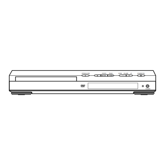
OPEN/CLOSE
DVD/CD
FM/AM
DOWN
VOLUME
UP
STANDBY/ON
0
7
6
—
+
TUNER
PHONES
Region No.
2
2
T – ZZV JULY 2002 Printed in Japan
ORDER NO.
RRV2653
Remarks
Advertisement
Table of Contents

Related Manuals for Pioneer XV-DV303


Summary of Contents for Pioneer XV-DV303
- Page 1 PIONEER CORPORATION 4-1, Meguro 1-chome, Meguro-ku, Tokyo 153-8654, Japan PIONEER ELECTRONICS (USA) INC. P.O. Box 1760, Long Beach, CA 90801-1760, U.S.A. PIONEER EUROPE NV Haven 1087, Keetberglaan 1, 9120 Melsele, Belgium PIONEER ELECTRONICS ASIACENTRE PTE. LTD. 253 Alexandra Road, #04-01, Singapore 159936 PIONEER CORPORATION 2002 T –...
-
Page 2: Safety Information
The interlock mechanism mentioned above becomes invalid in this mode. 2. When the cover is open, close viewing through the objective lens with the naked eye will cause exposure to the laser beam. ∗ : See page 78. XV-DV303... - Page 3 By following the instructions in this manual, be sure to apply the prescribed grease or glue to proper portions by the appropriate amount.For replacement parts or tools, the prescribed ones should be used. XV-DV303...
-
Page 4: Table Of Contents
7.1.2 DISPLAY OF THE MECHANISM ERROR HISTORY ..............84 7.1.3 TROUBLE SHOOTING ........................87 7.1.4 SEQUENCE AFTER POWER ON ....................89 7.1.5 PROTECTION CIRCUIT ........................92 7.1.6 DISASSEMBLY ..........................94 7.2 IC ................................99 7.3 CLEANING ............................118 8. PANEL FACILITIES ............................. 119 XV-DV303... -
Page 5: Specifications
DVD MENU ENTER (NVXJN : ADG1156) (ATB7009) (R6P, AA) SOUND MODE RETURN TUNE FOLDER FOLDER PROGRAM REPEAT RANDOM CLEAR TEST TONE CH LEVEL TIMER ENTER DVD DISP DIMMER TV CONTROL SHIFT INPUT CHANEL VOLUME 5.1ch DVD SURROUND SYSTEM AXD7337 XV-DV303... -
Page 6: Exploded Views And Parts List
For the applying amount of lubricants or glue, follow the instructions in this manual. (In the case of no amount instructions, apply as you think it appropriate.) 2.1 PACKING (for NVXJN Type) (for MYXJN Type) 10 - 16 (MYXJN Type Only) XV-DV303... - Page 7 Packing Case AHD8074 Packing Sheet AHG7102 NSP 22 Polyethylene Bag Z21-038 (2) CONTRAST TABLE XV-DV303/MYXJN and /NVXJN types are constructed the same except for the following: Part No. Symbol and Description Mark Remarks XV-DV303/MYXJN XV-DV303/NVXJN > AC Power Code ADG1154...
-
Page 8: Exterior Section
2.2 EXTERIOR SECTION Refer to "2.4 LOADING MECHANISM ASSY". NON-CONTACT SIDE Refer to "2.3 FRONT PANEL". CONTACT SIDE XV-DV303... - Page 9 AEC7372 Screw BPZ30P100FZK Bottom Plate AEC7420 Barrier S AEC7429 Barrier AEC7453 (2) CONTRAST TABLE XV-DV303/MYXJN and /NVXJN types are constructed the same except for the following: Part No. Symbol and Description Mark Remarks XV-DV303/MYXJN XV-DV303/NVXJN Rear Panel ANC8096 ANC8122 XV-DV303...
-
Page 10: Front Section
2.3 FRONT SECTION NON-CONTACT SIDE CONTACT SIDE XV-DV303... - Page 11 Mark No. Description Part No. DISPLAY ASSY AWU8035 HP ASSY AWU8037 5P FFC/30V ADD7378 13P FFC/60V ADD7379 Button DCS2 AAD7685 Display Window AAK8015 Front Panel AMB7824 AL Panel ANB7310 AEB7090 Screw BPZ30P100FZK Screw ABA1005 Screw BBZ30P080FNI Screw CBZ30P080FMC Spacer AEC7456 XV-DV303...
-
Page 12: Loading Mecanism Assy
Clamper VNL1924 Flexible Cable (26P) VDA1864 Screw JGZ17P028FMC Connector Assy 2P VKP2253 Screw Z39-019 Float Rubber VEB1327 Tray VNL1920 Belt VEB1330 Stabilizer VNE2253 Loading Base VNL1917 Float Base DVD VNL1918 Drive Cam VNL1919 Gear Pulley VNL1921 Loading Gear VNL1922 XV-DV303... - Page 13 GYA1001 Daifree No. 23 Daifree No. 23 GEM1036 Tray GEM1036 Tray Concave of unevenness Concave of unevenness Inner side of a ditch Daifree GEM1036 Bottom View Top View Side of the rib Concave of unevenness Daifree Daifree GEM1036 GEM1036 XV-DV303...
-
Page 14: Traverse Mechanism Assy
17 (Torque : 0.12 ± 0.01 N•m) Silicone Adhesive GEM1037 Silicone Adhesive GEM1037 4 (Adjustment Screw) 17 (Torque : 0.12 ± 0.01 N•m) DVDM Screw Tight Silicone Adhesive GYL1001 GEM1037 To DVDM 17 (Torque : 0.12 ± 0.01 N•m) To DVDM XV-DV303... - Page 15 Guide Bar VLL1514 Sub Guide Bar VLL1515 Hold Spring VNC1017 Joint Spring VNC1019 Support Spring VNC1020 NSP 11 Mechanism Chassis VNE2248 Slider VNL1811 Spacer VNL1913 Joint VNL1914 FFC Holder VNL1915 Screw BBZ20P050FZK Tapping Screw OBA8009 Screw PMA26P100FMC Damper Sheet VEB1335 XV-DV303...
-
Page 16: Block Diagram And Schematic Diagram
CN1961 CN1901 Loading Motor ASSY CN8002(1/2) CN8003 Loading 30,31 Motor CODEC & DIR CN8002 STEP VXX2505 IC8301 AK4586VQ (2/2) IC251 SPDL SPDL CN8001 Driver IC8101 BA6664FM CS493292 DD/DTS CN8003 CN8002 DSP ASSY (2/2) CN5620 (2/2) 10dB IC3002 CN5612 (2/2) XV-DV303... -
Page 17: Power Assy
Head Phone U-com IC5501 IC3901 PDC098A CN5611 HP ASSY CN5601 CONTROL ASSY FM/AM TUNER Control MODULE IC5701 IC5601 BU1923F MSM9202-01 FM/AM TUNER Antenna IN FL Tube Display DISPLAY ASSY Analog Selector LINE 1 IC3001 IC3003 LINE OUT Optical IN XV-DV303... -
Page 18: Loab Assy And Overall Wiring Diagram
DVDM ASSY (AWM7750) PICKUP ASSY-S (OXX8003) STEPPING MOTOR (CARRIAGE) : VXM1090 S101 : VSK1011 CN602 S2B-PH-K (RF) (RF) (RF) (RF) (RF) (RF) CN601 (RF) (RF) S5B-PH-K (RF) (RF) (RF) (RF) LOADING (RF) (RF) MOTOR ASSY : VXX2505 LOAB ASSY (VWG2279) XV-DV303... - Page 19 HP ASSY JA3001 (AWU8037) CONTROL ASSY (AWU8038) CN5504 DISPLAY ASSY (AWU8035) CN5611 CN5601 TRADE3 ASSY (AWU8044) (RF) : RF SIGNAL ROUTE : FOCUS SERVO LOOP LINE : TRACKING SERVO LOOP LINE : SLIDER SERVO LOOP LINE DSP ASSY (AWX8059) XV-DV303...
-
Page 20: Dvdm Assy 1/2
3.3 DVDM ASSY(1/2) DVDM ASSY(1/2) (AWM7750) IC351 M56788AFP FTS DRIVER (RF) (RF) (RF) (RF) (RF) (RF) XV-DV303... - Page 21 : DATA SIGNAL ROUTE : FOCUS SERVO LOOP LINE : TRACKING SERVO LOOP LINE : SLIDER SERVO LOOP LINE IC302 K6T1008V2E-TB70 WORK SRAM (1M) IC301 L6315ATXXTY (RAM) FRONT END IC : The power supply is shown with the marked box. XV-DV303...
-
Page 22: Dvdm Assy 2/2
3.4 DVDM ASSY(2/2) DVDM ASSY(2/2) (AWM7750) IC603 VYW1999 (MBM29LV800TA-90PFTN) PGM 8M FLASH MEMORY XV-DV303... - Page 23 : S-VIDEO OUT C SIGNAL ROUTE (B/Cb) (B/Cb) (S_Y) : S-VIDEO OUT Y SIGNAL ROUTE (R/Cr) : R/Cr SIGNAL ROUTE (G/Y) : G/Y SIGNAL ROUTE (B/Cb) : B/Cb SIGNAL ROUTE : AUDIO SIGNAL ROUTE : AUDIO (DIGITAL) SIGNAL ROUTE XV-DV303...
-
Page 24: Dvd If Assy
3.5 DVD IF ASSY DVD IF ASSY (AWM7677) CN1961 RN1903 RN1903 (S_C) (S_C) (S_Y) (S_Y) CN1962 (G/Y) (G/Y) (B/Cb) (B/Cb) (R/Cr) (R/Cr) RN2903 (S_C) RN2903 RN1903 (S_Y) (R/Cr) (G/Y) (B/Cb) RN1903 UN5212 XV-DV303... - Page 25 : VIDEO SIGNAL ROUTE : COMPONENT VIDEO G/Y SIGNAL ROUTE (S_Y) (B/Cb) : S-Y VIDEO SIGNAL ROUTE : COMPONENT VIDEO B/Cb SIGNAL ROUTE (S_C) (R/Cr) : S-C VIDEO SIGNAL ROUTE : COMPONENT VIDEO R/Cr SIGNAL ROUTE : DIGITAL AUDIO SIGNAL ROUTE XV-DV303...
-
Page 26: Dsp Assy
3.6 DSP ASSY DSP ASSY (AWX8059) XV-DV303... - Page 27 UNLOCK : 5V LOCK : 0V CN8001 : DIGITAL AUDIO SIGNAL ROUTE : C ch AUDIO SIGNAL ROUTE (FL) (SW) : FL ch AUDIO SIGNAL ROUTE : SW ch AUDIO SIGNAL ROUTE (SL) : SL ch AUDIO SIGNAL ROUTE XV-DV303...
-
Page 28: Fm/Am Tuner Module
3.7 FM/AM TUNER MODULE FM/AM TUNER MODULE (AXQ7229) FM FRONT END (FM) (FM) (FM) (FM) (FM) (AM) (AM) (AM) MW RF TUNING BLOCK (FM) (AM) OSC : 981 - 2052kHz 9k step XV-DV303... - Page 29 : The power supply is shown with the marked box. (TX) : AUDIO SIGNAL ROUTE (TUNER) (AM) : AM SIGNAL ROUTE (FM) : FM SIGNAL ROUTE (AM) (TX) (FM) (TX) (TX) (TX) CN201 (FM) (FM) (TX) (AM) L201 ATE7003 XV-DV303...
-
Page 30: Amp Assy
3.8 AMP ASSY CN3651 to FAN Motor CN3001 (FL) (SW) (SL) Non Distortion Circuit CN3002 AMP ASSY (AWM7720) XV-DV303... - Page 31 : Refer to P92. (FL) (SW) (SL) (FL) : FL ch AUDIO SIGNAL ROUTE (SL) : SL ch AUDIO SIGNAL ROUTE : C ch AUDIO SIGNAL ROUTE (SW) : SW ch AUDIO SIGNAL ROUTE XV-DV303...
-
Page 32: Control Assy 1/3, Trade2 And Trade3 Assys
3.9 CONTROL ASSY(1/3), TRADE2 and TRADE3 ASSYS TRADE3 ASSY (AWU8044) CN5617 CN5613 CN5615 CN5614 CN5612 CN5616 (FL) (SL) (FL) (SW) CN5618 CN5619 CN5620 XV-DV303... - Page 33 CN5522 CN5502 2/3,3/3 : DIGITAL AUDIO SIGNAL ROUTE (FL) : FL ch AUDIO SIGNAL ROUTE (SL) : Refer to P93. : SL ch AUDIO SIGNAL ROUTE : C ch AUDIO SIGNAL ROUTE (SW) : SW ch AUDIO SIGNAL ROUTE XV-DV303...
-
Page 34: Control Assy 2/3
3.10 CONTROL ASSY(2/3) CHANGE GAIN TABLE THROUGH XV-DV303... - Page 35 CONTROL ASSY(2/3) (AWU8038) Equalizer (FL) (SL) (SW) XV-DV303...
-
Page 36: Control Assy 3/3
3.11 CONTROL ASSY(3/3) CN3902 XV-DV303... - Page 37 CONTROL ASSY(3/3) (AWU8038) CN5701 RDS Decoder IC XV-DV303...
-
Page 38: Power Assy 1/2
3.12 POWER ASSY(1/2) ADG1154 : MYXJN ADG1156 : NVXJN POWER ASSY(1/2) (AWU8031) CN3031 CN3032 CN5521 CN5522 XV-DV303... - Page 39 : SL ch AUDIO SIGNAL ROUTE : C ch AUDIO SIGNAL ROUTE (SW) : SW ch AUDIO SIGNAL ROUTE : Refer to P92. NOTE FOR FUSE REPLACEMENT CAUTION FOR CONTINUED PROTECTION AGAINST RISK OF FIRE. REPLACE ONLY WITH SAME TYPE AND RATINGS ONLY. XV-DV303...
-
Page 40: Power Assy 2/2 And Trade1 Assy
3.13 POWER ASSY(2/2) and TRADE1 ASSY CAUTION : FOR CONTINUED PROTECTION AGAINST RISK OF FIRE. REPLACE ONLY WITH SAME TYPE NO. 491007 FOR IC25 MFD, BY TRADE1 ASSY LITTELFUSE INC. (AWU8036) CN3021 CN3011 (FL) (FL) (SW) (SW) CN8001 (SL) (SL) CN3022 CN3012 XV-DV303... - Page 41 (S_Y) : S_Y VIDEO SIGNAL ROUTE (S_C) : S_C VIDEO SIGNAL ROUTE (FL) : FL ch AUDIO SIGNAL ROUTE (SL) : SL ch AUDIO SIGNAL ROUTE : C ch AUDIO SIGNAL ROUTE (SW) : SW ch AUDIO SIGNAL ROUTE XV-DV303...
-
Page 42: Display And Hp Assys
3.14 DISPLAY and HP ASSYS DISPLAY ASSY (AWU8035) CN5601 (FL) : FL ch AUDIO SIGNAL ROUTE JA3901 CN3901 HP Terminal HP ASSY (AWU8037) XV-DV303... - Page 43 SWITCHES S5921 : Power ON S5922 : Vol Up S5923 : Vol Down S5924 : Band S5925 : Play/Pause S5926 : Stop S5927 : Open/Close XV-DV303...
-
Page 44: Waveforms
IC1941 - pin 21, 22 Foot of C1951 (IC1941 - pin 33) [Component Video output -Cb] [S Video output -C] V: 2V/div. H: 10µsec/div. V: 1V/div. H: 10µsec/div. IC1941 - pin 18, 19 [Component Video output -Cr] V: 2V/div. H: 10µsec/div. XV-DV303... -
Page 45: Pcb Connection Diagram
B C E SIDE A Transistor with resistor B C E Field effect SIDE B Chip Part transistor P.C.Board Resistor array 3-terminal regulator 4.1 LOAB ASSY SIDE A SIDE B LOAB ASSY LOAB ASSY (VNP1836-B) (VNP1836-B) CN52 LOADING MOTOR ASSY XV-DV303... -
Page 46: Dvdm Assy
4.2 DVDM ASSY SIDE A DVDM ASSY IC601 IC301 Q607 Q606 Q605 Q604 Q603 Q602 IC303 CN25 CN22 CN1962 CN1961 XV-DV303... - Page 47 SIDE A IC301 IC251 IC351 Q101 IC110 IC111 Q102 SPDL Motor PICKUP ASSY-S (VNP1866-D) 1961 CN601 XV-DV303...
- Page 48 SIDE B DVDM ASSY IC302 Q300 Q103 Q105 9 8 7 6 5 4 3 2 CN22 XV-DV303...
- Page 49 SIDE B IC605 IC603 Q651 IC304 IC604 Q601 Q652 7 6 5 4 3 2 1 0 3 2 1 0 (VNP1866-D) CN25 XV-DV303...
-
Page 50: Dvd If Assy
C1926 C1997 C1922 UPSIDE C1928 CONTACT R1992 L1981 C1925 R1981 V+3.3 IC1906 IC1906 C1994 V+2.5 IC1901 IC1901 V+3.5 C1903 GNDD GNDM C1991 IC1903 V+6M IC1903 C1907 DOUT C1993 IC1902 IC1902 C1932 C1931 C1992 VPRE+5M V+12 (ANP7425-B) UPSIDE CONTACT CN8001 XV-DV303... - Page 51 SIDE B SIDE B DVD IF ASSY Q1942 Q1941 IC1941 IC1986 Q1922 Q1921 IC1961 IC1962 Q1961 Q1931 Q1932 UPSIDE CONTACT (ANP7425-B) CN5102 XV-DV303...
-
Page 52: Dsp Assy
C8103 D8304 C8117 X8101 IC8102 D8302 D8303 C8115 R8312 R8317 D8301 C8324 C8323 C8314 C8305 C8306 R8301 L8302 C8315 C8320 C8304 C8915 C8916 C8303 R8304 C8403 R8403 C8402 R8325 C8302 C8325 R8404 R8401 R8320 CN8009 L8303 C8917 C8918 (ANP7442-B) XV-DV303... - Page 53 SBL- GNDA R8303 R 8 3 0 2 SBR+ C8319 SBR- C8318 R8310 R8402 C8327 R8308 C8313 C8326 C8901 C8902 R8309 C8312 C8311 R8321 C8404 L8304 C8921 C8922 AWX8059- -J AWX8079- -J AWX8059- -N AWX8079- -N AWX8188- -J (ANP7442-B) XV-DV303...
-
Page 54: Fm/Am Tuner Module
4.5 FM/AM TUNER MODULE SIDE A SIDE A FM/AM TUNER MODULE CN5701 (ANP7338-B) Q202 SIDE B SIDE B FM/AM TUNER MODULE (ANP7338-B) Q201 IC201 Q203 Q205 IC202 Q204 XV-DV303... -
Page 55: Display And Hp Assys
BAND VOL DOWN POWER ON OPEN/CLOSE S5922 S5927 S5926 S5925 S5924 S5923 S5921 V5601 5951 W108 VFDP D5662 L5563 (ANP7444-B) CN5611 SIDE B SIDE B IC5601 Q5691 (ANP7444-B) DISPLAY ASSY Q3903 Q3902 Q3905 HP ASSY Q3901 Q3906 R3914 (ANP7444-B) XV-DV303... -
Page 56: Amp Assy
D3323 W150 W178 GNDP W151 W179 R3322 D3324 D3326 D3393 R3328 R3318 W180 D3328 D3322 W181 R3320 W182 GNDP C3308 R3387 C3508 D3394 R3518 C3324 W200 R3520 W201 D3387 W155 FROUT D3385 R3388 D3386 W156 W203 D3388 W157 (ANP7440-B) XV-DV303... - Page 57 R 3 5 3 4 R3389 Q3534 R 3 5 4 0 SWOUT R3510 SWOUT C3504 GNDS C3506 R3512 FLOUT C3510 D3582 R3506 FLOUT D3544 R3538 GNDP GNDP R3544 FROUT Q3381 FROUT R3592 R3532 R3381 FROUT R3390 R3382 FAN SIDE Q3382 (ANP7440-B) XV-DV303...
-
Page 58: Control, Trade2 And Trade3 Assys
CONTROL Assy W133 W134 8038 C3908 C3918 W137 8039 W136 W130 8040 W132 GNDHP W135 8041 W131 AWU8048 8042 C3907 AWU8049 AWU8050 W906 C3911 W907 AWU8051 W101 W908 (ANP7445-B) CN5611 AWU8052 W909 CONTACT SIDE W910 W103 CONTACT SIDE CN5601 XV-DV303... - Page 59 W175 W166 W174 W165 W172 X5501 W170 W173 W169 GNDC W177 W168 W145 KN5791 W146 W137 W151 L5571 W136 W148 GNDD W135 W149 W150 AWU8048 AWU8049 AWU8050 W147 W154 AWU8051 W129 W118 AWU8052 W128 W126 W125 W124 W127 (ANP7445-B) XV-DV303...
-
Page 60: Control Assy
VD+5 VX+12 GNDD Q5571 Q5501 Q3065 GNDC DESTINATION Q5572 Q 5 5 0 1 IC3901 Q3908 UTEST Q3907 Q5573 CONTR Q3906 Q 5 5 7 3 AWU8038 AWU8039 AWU8040 AWU8041 Q3201 AWU8042 Q 3 2 0 1 AWU8048 AWU8049 XV-DV303... - Page 61 FLAC2 GNDFL VFL+5 VFDP MUTEC SCLK I C 3 9 0 1 Q 3 9 0 8 MDATA SDATA XPRCT VDET XTUNER XDVDRST SYSPOW CONTROL Assy AWU8038 AWU8050 AWU8039 Q114 AWU8051 AWU8040 AWU8052 (ANP7445-B) AWU8041 AWU8042 AWU8048 AWU8049 (ANP7445-B) XV-DV303...
-
Page 62: Power And Trade1 Assys
4.9 POWER and TRADE1 ASSYS SIDE A POWER ASSY AC IN CONTACT SIDE Q3641 W129 W130 IC51 Q51 PRINTED IC51 SIDE IC61 Transformer T1 CN1902 CN8001 XV-DV303... - Page 63 SIDE A TRADE1 ASSY W112 (ANP7444-B) CN3011 CN3012 W208 CN3002 CN3001 (ANP7444-B) Transformer T1 CN5102 CN1901 XV-DV303...
- Page 64 SRIN SLIN SWIN FRIN GNDA FLIN MUTE MUTEC SEN+8 VFL+5 VP+15 VA-12 VD+5 TUNER XPROTECT GNDR GNDR UN+8V UN+8V GNDFAN SLOUT SLOUT SROUT SROUT COUT COUT SWOUT SWOUT GNDS FLOUT FLOUT GNDP GNDP FROUT FROUT R 4 2 (ANP7444-B) XV-DV303...
- Page 65 SIDEB Q3632 Q3631 C8823 Q3636 Q3635 Q3633 Q3640 R8823 Q3645 Q3637 Q3645 Q3644 Q3644 Q3638 Q3639 C3463 R3463 Q3642 Q3611 Q3602 Q3601 Q3621 Q3622 Q3612 SECONDARY (ANP7444-B) XV-DV303...
-
Page 66: Pcb Parts List
IC604 K4S641632F-TC75 IC302 K6T1008V2E-TB70 IC301 L6315ATXXTY RESISTORS R121 RAB4C220J IC351 M56788AFP R123 RAB4C390J > IC303 PQ018EZ01ZP R340, R407 RS1/10S0R0J IC601 STI5519AVB-B0C R341 RS1/10S101J IC605 TC7WU04FU R126-R129, R176-R179 RS1/10S220J IC603 VYW1999 R254-R259 RS1/10S3R3J Q300, Q602-Q607 2SA1576A R326-R330 RS1/16S1001F Q652 DTC114TUA XV-DV303... - Page 67 SMD Power Inductor ATL7005 C8318, C8503, C8603 CCSRCH471J50 CAPACITORS C8115, C8116 CCSRCH6R0D50 C1931, C1932 CCSRCH102J50 C8302, C8501, C8601 CEAL100M16 C1920 CCSRCH121J50 C8001, C8014, C8024, C8103, C8307 CEAL101M10 C1901, C1904, C1906, C1912, C1925 CEV101M16 C8316, C8323 CEAL101M10 C1930, C1953 CEV101M16 C8320 CEAL220M6R3 XV-DV303...
- Page 68 DAN217 C227 CEAT220M25 C241 CEAT2R2M50 > D3581, D3582 DAN217 D3391, D3392 LT2A03 C243 CEAT330M16 D3389, D3390 MTZJ10C C228 CEAT3R3M50 > D98 MTZJ11B C237 CEAT470M10 > D72 MTZJ15C C211 CEJA1R0M50 C210 CEJA470M16 D3393, D3394 MTZJ18B C103, C104, C204, C238 CKSRYB102K50 XV-DV303...
- Page 69 IC5501 PDC098A C3025, C3026, C3033, C3034 CKSRYB103K50 Q3906 2SA1576A Q3005, Q3006, Q3009, Q3010, Q5501 2SC4081 C3067, C3068, C3083, C3084 CKSRYB103K50 Q5572, Q5711 2SC4081 C3091, C3092, C3102, C3115, C3116 CKSRYB103K50 C3119, C3120, C3130, C3141, C3142 CKSRYB103K50 Q3001, Q3002, Q3051-Q3057 2SD2114K XV-DV303...
- Page 70 CN5618 15P Plug AKP7060 C34, C41, C67 CEAT220M50 CN5615 21P Plug AKP7063 CEAT221M63 CN5616 11P Socket AKP7069 C3631 CEAT2R2M50 CN5619 15P Socket AKP7071 CEAT330M50 CN5617 21P Socket AKP7074 CEAT470M16 C3632, C8821, C8831 CEAT471M6R3 C8861, C8871 CEATR10M50 C12, C13 CFTLA103J50 XV-DV303...
- Page 71 COILS AND FILTERS L5563 LAU100J L5562 LAU220J SWITCHES AND RELAYS S5921-S5927 ASG7013 CAPACITORS C5674 CCSRCH470J50 C5564 CEJQ101M6R3 C5679, C5680 CEJQ1R0M50 C5678 CEJQ220M35 C5953 CEJQ470M16 C5671-C5673 CKSRYB102K50 C5677 CKSRYB103K50 C5562, C5563, C5665, C5666, C5675 CKSRYB223K50 C5952 CKSRYB223K50 C5676 Varistor (1000pF±30%) VCX1001 XV-DV303...
-
Page 72: Adjustment
Tangential Radial adjustment adjustment [Electrical Part] screw screw Electrical adjustments are not required. 6.1.2 JIGS AND MEASURING INSTRUMENTS Test mode remote control Screwdriver (large) Screwdriver (medium) TV monitor unit (GGF1067) Screw tight (GYL1001) DVD test disc Precise screwdriver (GGV1025) XV-DV303... - Page 73 Purpose: To set the sweep which was correct with the individual Traverse mechanism. Be sure to perform the following step finally when replaced Pickup, Traverse Mechanism and Spindle Motor. CLEAR GGF1067 Test mode remote control unit (It is necessary when performed adjustment procedure Ÿ.) XV-DV303...
- Page 74 Perform only trace, video and audio output are nothing. < When playback with the target address of disc (DVD)> For example, when playback with # 30000 During PLAY CHP/TIM Press keys in order 030000 TEST MODE: OFF POWER GGF1067 Test mode remote control unit XV-DV303...
-
Page 75: Mechanism Adjustment
Mechanism Base and turn each screw to adjust the height. (Refer to "6.1 ADJUSTMENT ITEMS AND LOCATION".) Spacer for Height adjustment Note: Turn the Short switch to Short side when Turn a flat side removing the Pickup Flexible Cable. into bottom (Refer to "7.1.6 DISASSEBLY".) XV-DV303... - Page 76 J : Min Disc playback normally. If error rate is OK, • The measurement of block error rate locks a root of tangential and radial adjustment screws with the Screw tight, and go to step Screw tight: GYL1001 Test mode end XV-DV303...
-
Page 77: Tuner Section
0 ± 50mV L201 of IC201 (Test point "Vtm") gets within 0 ± 50mV. Adjustment Pin 21/Pin23 PRODUCT MPX SG FM SG Voltmeter FM75Ω antenna terminal Fig.1 Adjustment Wiring Diagram FM/AM TUNER MODULE L201 IC201 pin 21 pin 23 SIDE B XV-DV303... -
Page 78: General Information
Perform only trace, video and audio output are nothing. = Screen display ON/OFF 1. Turn off the display by pressing the [AUDIO] (A8-1E) key of the remote control unit. 2. Turn on the display by pressing the [DISPLAY] (A8-43) key of the remote control unit. XV-DV303... - Page 79 • After the search, perform only trace and video and audio outputs are nothing. 4. Release the Search address input • Clear the address by pressing the [CLEAR] (A8-45) key. Release the address input mode when pressing the [CLEAR] key once again. XV-DV303...
-
Page 80: Display Specification Of The Test Mode
: [NTSC] PAL system : [PAL] Automatic setting : [AUTO] Scart terminal output [SK – ∗ ∗] (Display only the WY model which can do the output setting of scart terminal.) VIDEO : [00] S-VIDEO : [01] : [02] XV-DV303... - Page 81 Change black and green with toggle whenever pressing the key (the background color that green is using with SETUP NAVIGATOR). • Region confirmation mode (ESC+ A.MON + 1to 8) Input region No. after pressing the ESC+A.MON keys. When it is different from the setting, display and open the tray. XV-DV303...
-
Page 82: Specification Of Model Information Display
CUT ID / JTAG ID (two columns) (eight columns) 9 B.E VERSION Version of BACK END (version of ST core software) softwareVersion . softwareRevision / buildNumber 0 F.E VERSION Version of FRONT END (version of mechanism controller CHIP software) MainVersion / SubVersion XV-DV303... -
Page 83: Functional Specification Of The Service Mode
Indicate the mechanism error history by pressing the CHP/TIM key once again. Change indication by pressing the CHP/TIM key with toggle afterwards. Refer to the "Display of the Mechanism Error History". Indication plan contents Character in bold : Item name : Information display XV-DV303... -
Page 84: Display Of The Mechanism Error History
ACQUISITION ERROR 0x8∗ ACQUISITION TIMEOUT 0x9∗ PLL lost error 0x83 PLL lost timeout 0x93 DECODER ERROR 0xa∗ DECODER TIMEOUT 0xb∗ ID lost error 0xa3 ID lost timeout 0xb3 DEVICE ERROR 0xd∗ FAIL SAFE 0xe∗ SRAM error 0xd1 unexpected error 0xe1 XV-DV303... - Page 85 Do move to inner and outer periphery 1. Stepping motor of the stepping in the test mode? 2. Inside switch Stepping move timeout 0 x 54 Did timeout at stepping movement Do indicate "S-04" at the most inner 3. Driver periphery of the stepping? XV-DV303...
- Page 86 SRAM error 0 x d1 Cannot access SRAM 2. L6315 (Front End IC) Is not bus line short-circuiting? 3. L6315-SRAM bus line FAILSAFE (0 x e∗) 1. software runaway Unexpected error 0 x e1 Unexpected error 3. Software bug XV-DV303...
-
Page 87: Trouble Shooting
An opening screen is not Check the video signal path between BACK END IC (DVDM IC601) and displayed on the monitor The video circuit video-out terminal (LCD turns on. A mecha after BACK END (cf. block diagram) works.) Continues to next page. XV-DV303... - Page 88 Audio is not output Check the waveform (BCK, LRCK, MCLK, DATA). BACK END IC (DVDM IC601) (Picture is normal) Is signal output from IC1921-pin 7 and 8 on the DVD IF Assy ? AUDIO DAC IC (DVD IF IC1921) XV-DV303...
-
Page 89: Sequence After Power On
[FL controller] Outputs the signal which can communicate to BACK END (FP_XRDY) BACK END – FL controller communication The opening picture output [FRONT END] Identifies the following: • Slider positioning (INSIDE SW) • Spindle FG stop Disc detection (Focus control) XV-DV303... - Page 90 [SEQUENCE TIMING CHART] * 1 DSP initialization communication * 2 Move to normal communication directly when the initialization commnunication is finished. * 3 Not cancel MUTE when the initialization communication is not finished according to the DSP hard state. XV-DV303...
- Page 91 [SEQUENCE TIMING TABLE] l a i n i l – – – z i l l a i " t " l a i l a i l a i l a i l a i l a i XV-DV303...
-
Page 92: Protection Circuit
As the voltage of this point at normal state is (-) side, Q3631 does not turn ON. When the AC plug is pulled out and AC Power turns OFF, Q3631 base bias voltage becomes (+) side (Over 0.6V) and Q3631 turns And it operates following procedure. XV-DV303... - Page 93 [How to return from the protection circuit operating] XV-DV303 operates the protection circuit under the following conditions and makes the set Power OFF. 1. When major voltage becomes down to low level because of short-circuit or without connection. 2. When detecting abnormal thermal rise by the thermistor.
-
Page 94: Disassembly
Remove the Screws × 3 Remove the Connectors × 2 Remove the CONTROL Assy Front Panel Section Unhook Unhook ×2 Slit Small Square-bar Screwdriver ×2 Small Square-bar Screwdriver Protruding Unhook portion Drive Gear CONTROL Loading Mechanism Assy Assy Bottom View XV-DV303... - Page 95 Connection Cable for Service rub the Clamper. (GGD1222) Connection Cable for Service Playback the Test Disc, (GGD1266) and diagnosis the DVDM Assy POWER Assy CONTROL Assy TRADE 2 Assy AMP Assy DVDM Assy DVD IF Assy Loading Mechanism Assy Spacer Spacer XV-DV303...
- Page 96 In the Tray insertion, insert it after matching a triangle mark of the Loading Base and a position of pin of the Drive Cam. Loading Base Triangle mark × 2 Traverse Mechanism Assy It may be some different in the shape. Exchange Drive Cam XV-DV303...
- Page 97 It may be some different in the shape. Joint Silicone Adhesive GEM1037 Remove two Skew Screws and two Skew Springs. Remove the Pickup Assy. Exchange Pickup Assy Skew Screw Skew Spring Skew Screw Skew Spring It may be some different in the shape. XV-DV303...
- Page 98 Move the Pickup to the innermost of the disc. Perform the styling as shown in figure below. Lose slack Fold position of step Bottom View Bottom View Fold it at the position of reference line. Reference line Bottom View Bottom View XV-DV303...
- Page 99 – – – – – – – – – – , t u s i r s ' l , t u s i r s ' l t f i – – – t s i XV-DV303...
- Page 100 – s ' l s ' l s ' l s ' l s ' l s ' l s ' l s ' l – – – t i r – t i r – t i r XV-DV303...
- Page 101 CS493292 (DSP ASSY : IC8101) • DSP for Decode Pin Function – – – – – – l l u – – – l l u – l l u l l u XV-DV303...
- Page 102 Control reference pin of output voltage Output pin Output voltage control pin GND pin Power save pin FG signal output pin Power supply pin Gain switching pin Hall signal input pins Motor power pin Resistor connection pin for output current detection Hall bias pin XV-DV303...
- Page 103 L6315ATXXTY (DVDM ASSY : IC301) • Front End IC Block Diagram XV-DV303...
- Page 104 − 36 PC[0] (NC) Digital I/O 37 PC[1] (PS) Digital I/O Driver IC power save 38 PC[2] (FG) Digital I/O FG pulse input 39 PC[3] (SB) Digital I/O Spindle short brake 40 PC[4] (SLDPOS) Digital I/O Slider position input XV-DV303...
- Page 105 72 RAM_DQ[3] Digital I/O SRAM data 73 RAM_DQ[4] 74 RAM_DQ[5] 75 RAM_DQ[6] 76 RAM_DQ[7] 77 VDD3S Digital supply VDD core 78 VSS Digital ground VSS core 79 OUT_REQ Reserved Must be set to ground 80 OUT_ERR Digital output Output interface XV-DV303...
- Page 106 Digital supply VDD I/O 116 RESET_IN Digital input Global reset signal 117 VCC18DAC Analog supply DAC analog power supply 118 STEPER1 Analog output DAC spindle motor 119 STEPER2 Analog output DAC sled motor 120 REFEXT Analog input DAC external reference XV-DV303...
- Page 107 Analog output Laser control DAC reference 141 LMD1 Analog input Laser control monitor diode 1 142 LMD2 Analog input Laser control monitor diode 2 143 GNDL Analog ground Ground for laser control detection 144 VBGFILT Analog input Bandgap filtering input XV-DV303...
- Page 108 M56788AFP (DVDM ASSY : IC351) • FTS Driver IC Block Diagram XV-DV303...
- Page 109 STI5519AVB-B0C (DVDM ASSY : IC601) • Back End IC Block Diagram XV-DV303...
- Page 110 R / Cr 28 VREF_RGB RGB DAC reference 29 IREF_RGB RGB DAC electric current reference − 30 VDD/YCC YC circuit 2.5 V Power supply − 31 VSS_YCC YC circuit Ground 32 Y_OUT 33 C_OUT 34 CV_OUT 35 VREF_YC YCC DAC reference XV-DV303...
- Page 111 55 A_MCLK Audio DAC Master clock 56 A_LRCK Audio DAC L/R clock 57 DOUT S/PDIF(IEC60958) digital audio output. 58 SMI_A4 59 SMI_A5 60 SMI_A6 SMI SDRAM addresss 61 SMI_A7 62 SMI_A8 63 SMI_A9 − 64 VDD_2V4 2.5 V Power supply XV-DV303...
- Page 112 In case of NOT Karaoke model, this port is N.C.(output). 103 KDSP_XCS Karaoke model Exteranal DSP chip select 'L'. In case of NOT Karaoke model, this port is N.C.(output). 104 KDSP_THRU Karaoke model Exteranal DSP through pass mode 'L'. XV-DV303...
- Page 113 Flash memory Chip Eenable 'L' 133 − TP-x 134 − TP-x 135 SD_XRAS Debug SDRAM RAS 'L' − 136 VDD_3V3 3.3V Vdd − 137 VSS 138 − TP-x 139 SD_XCAS Debug SDRAM CAS 'L' 140 SD_XCS Debug SDRAM Chip Select 'L' XV-DV303...
- Page 114 2.5 V Power supply − 172 VSS Ground 173 CPU_A11 174 CPU_A12 175 CPU_A13 176 CPU_A14 177 CPU_A15 178 CPU_A16 FLASH, Debug SDRAM address 179 CPU_A17 180 CPU_A18 181 CPU_A19 182 CPU_A20 183 CPU_A21 − 184 VDD_3V3 3.3 V Power supply XV-DV303...
- Page 115 'H' show tray loading "OPEN" complete position. 205 XCLOSE 'H' show tray loading "CLOSE" complete position. Front Panel interface. 206 FP_ACK Hand-shake (acknowledge) output. Front Panel interface. 207 FP_SCK (Soft) Serial transfer clock output. Front Panel interface. 208 FP_SI (Soft) Serial transfer data input. XV-DV303...
- Page 116 DATA 2 4× / 8× Oversampling Enhanced Digital Filter Multi-level with Delta-Sigma Function Modulator Controller ML 15 Serial Control MC 14 Output Amp and Port Low-pass Filter MD 13 System Clock System Clock Power Supply Zero Detect SCK 16 Manager XV-DV303...
- Page 117 13 CLP Input clamp select 30 VOUT Signal output (V) 14 CbIN Component input (Cb) 31 VSAG SAG correction (V) 15 MUTE2 Mute select 32 GND2 16 CrIN Component input (Cr) 33 COUT Crroma output 17 GND2 34 VCC2 XV-DV303...
-
Page 118: Cleaning
7.3 CLEANING Before shipping out the product, be sure to clean the following positions by using the prescribed cleaning tools: Position to be cleaned Cleaning tools Pickup leneses Cleaning liquid : GEM1004 Cleaning paper : GED-008 XV-DV303... -
Page 119: Panel Facilities
Switches to the tuner function and toggles between the AM and FM bands VOLUME buttons Adjusts the volume STANDBY/ON button Switches the player on or into standby Remote sensor Timer indicator Lights when the timer is set PHONES jack Headphone jack XV-DV303... -
Page 120: Remote Control
VOLUME Adjusts the volume DVD SETUP Displays (or exits) the on-screen DVD display SYSTEM SETUP (SHIFT+DVDSETUP) Press to make various system settings in standby; choose your surround sound settings when the unit is switched on XV-DV303... - Page 121 Selects a repeat play mode Switches the TV input RANDOM Selects a random play mode CHANNEL +/– Selects channels on the TV TEST TONE VOLUME +/– Outputs the test tone (for speaker setup) Adjusts the volume on the TV XV-DV303...
- Page 122 Surround listening modes is selected “Dolby”,”Pro Logic” and the double-D symbol are trademarks of Dolby Laboratories. *2 “DTS” and “DTS Digital Surround” are registered This lights to indicate decoding of a trademarks of Digital Theater Systems, Inc. DTS *2 signal XV-DV303...
Need help?
Do you have a question about the XV-DV303 and is the answer not in the manual?
Questions and answers
I don't have a remote control for pionee ..to put off timer