Table of Contents
Advertisement
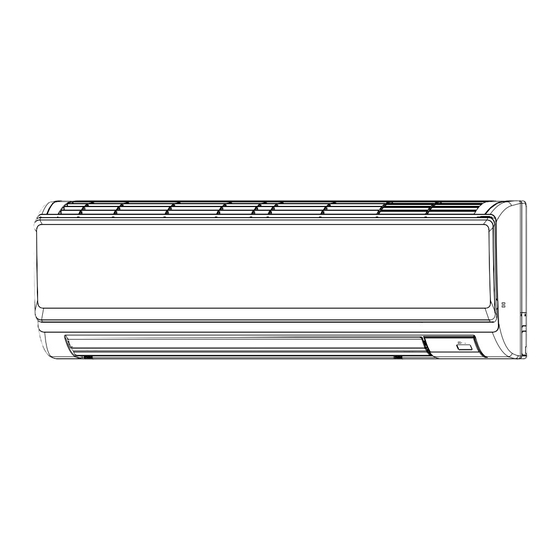
SPLIT-TYPE, HEAT PUMP AIR CONDITIONERS
TECHNICAL & SERVICE MANUAL
Indoor unit
[Model names]
PKFY-P12NHMU-E
PKFY-P15NHMU-E
PKFY-P18NHMU-E
INDOOR UNIT
[Service Ref.]
PKFY-P12NHMU-E
PKFY-P15NHMU-E
PKFY-P18NHMU-E
R410A
R22
CONTENTS
1. PART NAMES AND FUNCTIONS .......... 2
2. SPECIFICATION ..................................... 4
3. OUTLINES AND DIMENSIONS .............. 6
4. WIRING DIAGRAM ................................. 7
5. REFRIGERANT SYSTEM DIAGRAM .......... 8
6. MICROPROCESSOR CONTROL ........... 9
7. TROUBLESHOOTING .......................... 14
8. DISASSEMBLY PROCEDURE ............. 21
PARTS CATALOG (OCB460)
April 2009
No. OCH460
Note:
• This manual describes
only service data of the
indoor units.
• RoHS compliant products
have <G> mark on the
spec name plate.
Advertisement
Table of Contents

Related Manuals for Mitsubishi Electric PKFY-P12NHMU-E


Summary of Contents for Mitsubishi Electric PKFY-P12NHMU-E
-
Page 1: Table Of Contents
No. OCH460 TECHNICAL & SERVICE MANUAL R410A Indoor unit Note: [Model names] [Service Ref.] • This manual describes PKFY-P12NHMU-E PKFY-P12NHMU-E only service data of the indoor units. • RoHS compliant products PKFY-P15NHMU-E PKFY-P15NHMU-E have <G> mark on the spec name plate. -
Page 2: Part Names And Functions
PART NAMES AND FUNCTIONS Filter Air intake Indoor unit Vane Louver Air outlet Wireless remote controller CHECK TEST RUN display display CHECK and TEST RUN display indicate that the unit is being checked or test-run. Lights up while the signal is transmitted to the indoor unit when the button is pressed. -
Page 3: Wired Remote Controller
Wired remote controller Display Section Day-of-Week “Sensor” indication Displayed when the remote controller Shows the current day of the week. sensor is used. For purposes of this explanation, Time/Timer Display all parts of the display are shown Shows the current time, unless the simple or Auto Off as lit. -
Page 4: Specification
SPECIFICATION 2-1. Specifi cations PKFY-P18NHMU-E PKFY-P12NHMU-E PKFY-P15NHMU-E Service Ref. Power source 1-phase 208-230V 60Hz Cooling capacity (Nominal) Btu/h 12,000 15,000 18,000 0.03 0.03 Power input 0.03 0.30 0.30 0.30 Current input Heating capacity (Nominal ) Btu/h 13,500 17,000 20,000 0.03 0.03... -
Page 5: Sound Levels
2-2. Electrical parts specifi cations Service Ref. Symbol PKFY-P12NHMU-E PKFY-P15NHMU-E PKFY-P18NHMU-E Parts name Room temperature Resistance 30°F/15.8k , 50°F/9.6k , 70°F/6.0k , 80°F/4.8k , 90°F/3.9k , 100°F/3.2k TH21 thermistor Liquid pipe thermistor Resistance 30°F/15.8k , 50°F/9.6k , 70°F/6.0k , 80°F/4.8k , 90°F/3.9k , 100°F/3.2k... -
Page 6: Outlines And Dimensions
OUTLINES AND DIMENSIONS 15-3/16(387) 7-1/2(192) PKFY-P12, 15, 18NHMU-E Unit : inch (mm) Top side Mount board 23-9/16(599) Front side Right side 9-13/16(249) 3/16(5) Left side 2-1/8 27-1/16(688) 6-1/16(155) (55) Knockout hole 35-3/8(898) Knockout hole for left piping for right piping Front side(Grille open) Sleeve Through hole... -
Page 7: Wiring Diagram
WIRING DIAGRAM PKFY-P12, 15, 18NHMU-E NAME NAME SYMBOL SYMBOL INDOOR CONTROLLER BOARD TH21 THERMISTOR ROOM TEMP. DETECTION ( 32°F/15k ,77°F /5.4kΩ) CN24 CONNECTOR EXTERNAL HEATER CN32 REMOTE SWITCH TH22 PIPE TEMP. DETECTION / LIQUID ( 32°F/15k ,77°F /5.4kΩ) CN51 CENTRALLY CONTROL CN52 REMOTE INDICATION TH23... -
Page 8: Refrigerant System Diagram
REFRIGERANT SYSTEM DIAGRAM PKFY-P12, 15, 18NHMU-E Gas pipe thermistor TH23 Strainer (#50mesh) Gas pipe Gas pipe thermistor TH24 Flare connection Liquid pipe thermistor TH22 Heat exchanger Liquid pipe Linear expansion valve Room temparature thermistor TH21 Strainer1 (#50mesh) Strainer2 (#100mesh) Strainer (#100mesh) Unit : mm (inch) Service Ref. -
Page 9: Microprocessor Control
MICROPROCESSOR CONTROL INDOOR UNIT CONTROL 6-1. COOL OPERATION <How to operate> Press POWER ON/OFF button. TIME SUN MON TUE WED THU FRI SAT TIMER Press the operation MODE button to display COOL. AFTER AFTER ERROR CODE FUNCTION û Fû C FILTER û... -
Page 10: Dry Operation
6-2. DRY OPERATION <How to operate> Press POWER ON/OFF button. TIME SUN MON TUE WED THU FRI SAT TIMER AFTER AFTER Press the operation MODE button to display DRY. ERROR CODE FUNCTION û Fû C FILTER û Fû C Press the TEMP. button to set the desired temperature. WEEKLY SIMPLE ONLY1Hr. -
Page 11: Fan Operation
6-3. FAN OPERATION <How to operate> Press POWER ON/OFF button. TIME SUN MON TUE WED THU FRI SAT Press the operation MODE button to display FAN. TIMER AFTER AFTER ERROR CODE FUNCTION û Fû C FILTER û Fû C WEEKLY SIMPLE ONLY1Hr. -
Page 12: Heat Operation
6-4. HEAT OPERATION <How to operate> Press POWER ON/OFF button. Press the operation MODE button to display HEAT. TIME SUN MON TUE WED THU FRI SAT Press the TEMP. button to set the desired temperature. TIMER AFTER AFTER ERROR CODE FUNCTION NOTE: The set temperature changes 2°F when the button is... - Page 13 From the preceding page Control modes Control details Remarks 2-3. Thermo OFF mode 2. Fan When the thermoregulating function changes to OFF, the indoor fan operates in [Extra low]. 2-4. Heat defrosting mode The indoor fan stops. (1) Initial setting: OFF → HEAT···[last setting] 3.
-
Page 14: Troubleshooting
TROUBLESHOOTING 7-1. HOW TO CHECK THE PARTS PKFY-P12, 15, 18NHMU-E Parts name Check points Room temperature Disconnect the connector then measure the resistance with a tester. thermistor (TH21) (At the ambient temperature 50°F~86°F) Liquid pipe temperature Normal Abnormal thermistor (TH22) Refer to the next page for the details. - Page 15 <Output pulse signal and the valve operation> Closing a valve : 1 → 2 → 3 → 4 → 1 Output Output Opening a valve : 4 → 3 → 2 → 1 → 4 (Phase) The output pulse shifts in above order. Note: •...
- Page 16 7-1-3. DC Fan motor (fan motor/indoor controller circuit board) Check method of DC fan motor (fan motor/indoor controller circuit board) Notes · High voltage is applied to the connecter (CNMF) for the fan motor. Pay attention to the service. · Do not pull out the connector (CNMF) for the motor with the power supply on. board and fan motor.) (It causes trouble of the indoor controller circuit Self check...
-
Page 17: Function Of Dip Switch
7-2. Function of Dip switch PKFY-P12, 15, 18NHMU-E Operation by switch Effective Switch Pole Function Remarks timing Thermistor<Room temperature> Indoor unit Built-in remote controller Address board position Filter clogging detection Provide Not provide <Initial setting> Filter cleaning sign 2,500 hr 100 hr 1 2 3 4 5 6 7 8 9 10 Fresh air intake... - Page 18 Effective Operation by switch Remarks Switch timing SW11 Address board SW12 SW11 1s digit How to set addresses address Example : If address is "3", remain SW12 <Initial setting> setting (for over 10) at "0", and match SW11 (for 1 to 9) SW12 SW11 SW12...
- Page 19 7-3. TEST POINT DIAGRAM 7-3-1. Indoor controller board CNMF PKFY-P12NHMU-E Connect to the fan motor (MF) 1-3 : DC294~325V PKFY-P15NHMU-E 4-3 : DC15V FUSE PKFY-P18NHMU-E 5-3 : DC0~6V 3.15A 250V 6-3 : DC0 or DC15V (Stop) DC7.5V (Operation) (12VDC pluse)
- Page 20 7-3-2. Wireless remote controller board PKFY-P12NHMU-E PKFY-P15NHMU-E PKFY-P18NHMU-E LD101 Connect to the indoor controller board (I.B) 7-3-3. Address board PKFY-P12NHMU-E PKFY-P15NHMU-E PKFY-P18NHMU-E Function setting SW12 SW11 SW14 Address setting Address setting Branch No. 10ths DIGIT 1s DIGIT...
-
Page 21: Disassembly Procedure
DISASSEMBLY PROCEDURE PKFY-P12NHMU-E PKFY-P15NHMU-E PKFY-P18NHMU-E Be careful when removing heavy parts. OPERATION PROCEDURE PHOTOS & ILLUSTRATIONS 1. REMOVING THE LOWER SIDE OF THE INDOOR Figure 1 UNIT FROM THE INSTALLATION PLATE (1) Remove the front panel. (2) Insert the screw driver to the corner hole at both left and right side as shown in the figure 1. -
Page 22: Operation Procedure
OPERATION PROCEDURE PHOTOS Electrical box cover (top) Electrical box Photo 3 3. REMOVING THE INDOOR CONTROLLER BOARD Screw (side cover) cover (side) Screw (top cover) AND WIRELESS CONTROLLER BOARD (1) Remove the front panel. (Refer to 2.) Room temp. (2) Remove the room temp. thermistor TH1. (see Photo 3) thermistor (3) Remove the electrical box covers (screw 4 ×... - Page 23 OPERATION PROCEDURE PHOTOS Electrical box cover (side) 5. REMOVING THE NOZZLE ASSEMBLY (with VANE Photo 8 Electrical box cover (top) and VANE MOTOR) AND DRAIN HOSE Screw (side cover) Screw (top cover) (1) Remove the front panel (Refer to 2.). (2) Remove the electrical box cover.
- Page 24 Fixture (right) Room temp. thermistor (TH21) HEAD OFFICE : TOKYO BLDG., 2-7-3, MARUNOUCHI, CHIYODA-KU TOKYO 100-8310, JAPAN Copyright 2009 MITSUBISHI ELECTRIC ENGINEERING CO., LTD. Distributed in Apr. 2009 No. OCH460 PDF 7 New publication, effective Apr. 2009 Made in Japan...
Need help?
Do you have a question about the PKFY-P12NHMU-E and is the answer not in the manual?
Questions and answers