Table of Contents
Advertisement
Advertisement
Table of Contents

Related Manuals for Vermona DRM1 MKII


Summary of Contents for Vermona DRM1 MKII
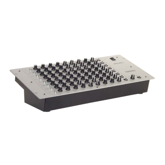
- Page 1 OWNER’S MANUAL „DRM1 MKII“ analog drum synthesizer...
-
Page 2: Table Of Contents
Every sound parameter of the DRM1 MKII has it’s own controller, so it’s easy to use and you’ll always have the best overview over the settings. -
Page 3: General
Spare parts or modifications Modification instructions and schematic information should only be used from service departments of our official authorized VERMONA dealers. To prevent the risk of electrical shock, please do not open or modify the unit yourself. Before opening the unit always disconnect the power lead/AC Adapter. -
Page 4: Control Features And Connections
Control Features and Connections Front Panel POWER switch POWER LED MASTER: Sets the main output level of the DRM1 MKII. TRIG: Button for triggering the sound. TRIG LED: Flashes when the sound will be triggered. Sound programming parameter controls PAN: Places the sound in the stereo field. -
Page 5: Getting Started
Connect the DRM1 MKII with the included power cord to the power socket. • Connect the outputs of the DRM1 MKII (11) with the line inputs of your mixing console, amplifier, … (Alternatively, you can use a headphone with the Phones jack (10).) •... -
Page 6: The Channels Of The Drm1 Mkii
The Channels of the DRM1 MKII In this chapter each channel of the DRM1 MKII will be described shortly, for a better understanding of the programming parameters. The parameters PAN and VOLUME as soon as the TRIG button, occurs in every channel. So they were overlooked in the channel descriptions. -
Page 7: The Channel Multi
The Channel MULTI Structure The MULTI channel has three VCOs, which generate triangle waveforms. The frequencies of the oscillators will be set with the three pitch controllers. PITCH1 sets the base frequency; PITCH2 and PITCH3 detune the other two oscillators relatively to PITCH1. If a pitch controller is set to minimum position, the corresponding oscillator is inactive. -
Page 8: The Channels Cymbal1, Cymbal2
The closed hat has a fixed decay time, which is short and independent of the DECAY controller (in this mode it has no function).Whenever the DRM1 MKII will be switched on, the TRIG button triggers the cymbal/open hat –... -
Page 9: Midi Application
Send eight note-on messages from your midi source to the DRM1 MKII. (i.e. by pressing eight keys on a keyboard/synthesizer) The first note value that will be received from the DRM1 MKII, is valid for the first drum channel (DRUM1). When the device receives the midi message, the TRIG LED (5) of the corresponding channel flashes and its sound can be heard. -
Page 10: Individual Outs/Inserts
NOTE: If the DRM1 MKII is in the learn mode and doesn’t receive any midi message, the factory settings will be restored. It is possible to set more channels of the DRM1 MKII to the same note-on value. This can be used for special sounds, but it can also be a possible problem source. -
Page 11: Declaration Of Conformity
Declaration of conformity for VERMONA DRM1 MKII – analog drum synthesizer We declare under our sole responsibility that this product is in conformity with the following standards or standardization documents in attention of operation conditions and installation arrangements acc. to operating...
Need help?
Do you have a question about the DRM1 MKII and is the answer not in the manual?
Questions and answers