Table of Contents
Advertisement
T
3 9 0 2 4
H E
4 2 5 D C
I
N S T A L L A T I O N
Important Safety Information
Technical Data
The 390 24V Operator General Characteristics
Exploded View, 390 24V Operator
390 24V Operator Parts List
The 425 D Control Panel General Description
Connect Accessory Devices
Setting the DIP Switches
Obstacle Recognition
Fuse Ratings
Safety in Gate Design
Troubleshooting
O
V
O N T R O L
M
CONTENTS
P E R A T O R A N D
P
:
A N E L
A N U A L
2
4
5
6
6
6
6
7
7
7
10
12
13
14
14
14
14
15
16
17
17
19
20
20
20
21
21
22
24
J u l y , 2 0 0 6
4 2 5 D C o n t r o l P a ne l
I n s t a l l a ti o n M a n u a l
303 Lexington Avenue
Cheyenne, WY 82007
www.faacusa.com
Advertisement
Table of Contents

Related Manuals for FAAC 390 24 V


Summary of Contents for FAAC 390 24 V
-
Page 1: Table Of Contents
Connect Accessory Devices Set Operating Modes Setting the DIP Switches Obstacle Recognition Programming Display Descriptions Programming the Motor Run Time Fuse Ratings Maintenance Safety in Gate Design FAAC International, Inc. Troubleshooting Limited Warranty 303 Lexington Avenue Cheyenne, WY 82007 www.faacusa.com... - Page 2 J u l y , 2 0 0 6 3 9 0 2 4 v O pe r a t or A n d P a g e 2 4 2 5 D C o n t r o l P a ne l I n st a l l a t i o n M a n u a l M PORTANT AFE TY NFORM ATION...
- Page 3 • Do not touch the equipment with damp or periodically check and maintain the equipment. humid hands or feet. U.L. C FAAC O LASS AND PERATOR Model Duty Cycle Typical Use Class I: Residential Vehicular Gate Operator •...
- Page 4 J u l y , 2 0 0 6 3 9 0 2 4 v O pe r a t or A n d P a g e 4 4 2 5 D C o n t r o l P a ne l I n st a l l a t i o n M a n u a l ECHNICAL 390 O PERATOR...
-
Page 5: J U L Y , 2 0 0 6
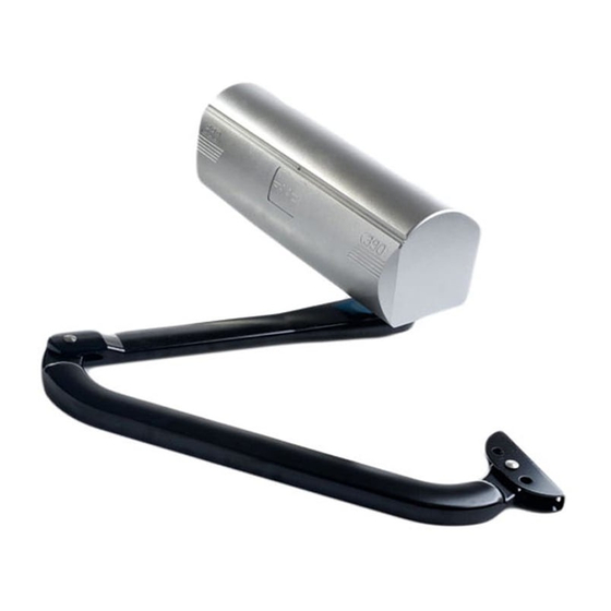
4 2 5 D C o n t r o l P a ne l I n s t a l l a ti o n M a n u a l NPACKING THE PERATOR When you receive your 390 24 V Operator, complete the following steps. 390 Motor Assembly Inspect the shipping box for physical damage such as a torn carton. -
Page 6: Installation Instructions
24v Operator include built in reverse on contact and a torque adjustment that controls the force transmitted to The FAAC 390 24v Operator is an automatic gate the gate leaf through the 390 24v Operator. operator for a residential swinging gate leaf that is ideal for large columns. -
Page 7: Install The Operator
J u l y , 2 0 0 6 3 9 0 2 4 v O pe ra t o r A n d P a g e 7 4 2 5 D C o n t r o l P a ne l I n s t a l l a ti o n M a n u a l If the gate has to be operated manually in the event of a ∗... - Page 8 J u l y , 2 0 0 6 3 9 0 2 4 v O pe r a t or A n d P a g e 8 4 2 5 D C o n t r o l P a ne l I n st a l l a t i o n M a n u a l Figure 5.
- Page 9 J u l y , 2 0 0 6 3 9 0 2 4 v O pe ra t o r A n d P a g e 9 4 2 5 D C o n t r o l P a ne l I n s t a l l a ti o n M a n u a l Hinge Figure 6.
-
Page 10: 390 Limit Switch Instructions
J u l y , 2 0 0 6 3 9 0 2 4 v O pe r a t or A n d P a g e 1 0 4 2 5 D C o n t r o l P a ne l I n st a l l a t i o n M a n u a l Figure 8 Figure 7 Figure 7 shows how to attach the operator... - Page 11 18 AWG × × Power Switch 14 AWG 14 AWG × × FAAC 5 Wire Cable for Master/Slave Connection and 18 AWG 18 AWG Junction Box Gate stops provided by built in limit switch × × FAAC Key Activated Switch (T10)
- Page 12 J u l y , 2 0 0 6 3 9 0 2 4 v O pe r a t or A n d P a g e 1 2 4 2 5 D C o n t r o l P a ne l I n st a l l a t i o n M a n u a l The 390 24v Operator...
-
Page 13: Parts List
J u l y , 2 0 0 6 3 9 0 2 4 v O pe ra t o r A n d P a g e 1 3 4 2 5 D C o n t r o l P a ne l I n s t a l l a ti o n M a n u a l Parts List 390 24v Operator PART NO. -
Page 14: Installing The 425 D Control Panel
Checking the direction of the motor's rotation ENERAL ESCRIPTION ∗ Connecting other devices to the control panel ∗ The FAAC 425 D control panel is used to operate the Set operating modes following models. ONNECT THE OWER UPPLY Swing gate operators:... - Page 15 (N.C.) type. Where you connect a device depends on whether you want the device to operate during opening or during closing. RESET : UL does not recognize the FAAC system with loop detectors or safety edges. STOP FSW-CL FSW-OP...
- Page 16 OPEN A and COM. illuminated except when the reversing devices, for opening and closing, respectively, are triggered. Use the : The FAAC radio receiver plugs into LEDs and the next table to determine if the accessory the 5 prongs labeled CN5 (Quick connect devices you have installed are operating properly.
- Page 17 J u l y , 2 0 0 6 3 9 0 2 4 v O pe ra t o r A n d P a g e 1 7 4 2 5 D C o n t r o l P a ne l I n s t a l l a ti o n M a n u a l during closing reopens...
- Page 18 J u l y , 2 0 0 6 3 9 0 2 4 v O pe r a t or A n d P a g e 1 8 4 2 5 D C o n t r o l P a ne l I n st a l l a t i o n M a n u a l Activation Devices Magnetic Lock (Free Exit Loop/ Phone/ Keypad)
- Page 19 J u l y , 2 0 0 6 3 9 0 2 4 v O pe ra t o r A n d P a g e 1 9 4 2 5 D C o n t r o l P a ne l I n s t a l l a ti o n M a n u a l DISPLAY DESCRIPTION ROGRAMMING...
-
Page 20: Display Descriptions
4. Give the panel an open activation with any normally open device wired to the OPEN A and COM terminals or the FAAC plug in radio receiver. Motor 2 should close first, followed by motor 1. 5. If either gate moves toward the open direction, touch the two RESET (JMP1) pins, (see figure 2) with a small screwdriver or piece of wire. -
Page 21: Maintenance
4 2 5 D C o n t r o l P a ne l I n s t a l l a ti o n M a n u a l AINTENANCE 390 24VO 425 D C PERATOR ONTROL ANEL Keep the Control Panel free from spider webs, insects, The FAAC 390 24V Operator requires no maintenance. etc. Otherwise Control Panel requires Periodically inspect the operator, however, to ensure maintenance. - Page 22 J u l y , 2 0 0 6 3 9 0 2 4 v O pe r a t o r A n d P a g e 2 2 4 2 5 D C o n t ro l P a ne l I n s t a l l a ti o n M a n u a l ROUBLESHOOTING WARNING! Before you do any work on the control panel, be sure to turn off the main power.
- Page 23 J u l y , 2 0 0 6 3 9 0 2 4 v O pe r a t or A n d P a g e 2 3 4 2 5 D C o n t r o l P a ne l I n s t a l l a ti o n M a n u a l OTES...
-
Page 24: Faac International, Inc
Neither FAAC S.p.A. related systems and equipment manufactured by FAAC or FAAC International, Inc., shall be liable for any loss or S.p.A. and distributed by FAAC International, Inc., to be damage whatsoever resulting, directly or indirectly, free from defects in material and workmanship under from the use or loss of use of the product(s).
Need help?
Do you have a question about the 390 24 V and is the answer not in the manual?
Questions and answers