Table of Contents
Advertisement
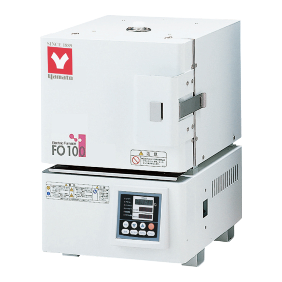
Muffle Furnace
Model
FO 100/200/300/310/410
/510/610/710/810
Instruction Manual
Thank you for purchasing "Muffle Furnace, FO
Series" of Yamato Scientific Co., Ltd.
To use this unit properly, read this "Instruction
Manual" thoroughly before using this unit.
Keep this instruction manual around this unit for
referring at anytime.
WARNING!:
Carefully read and thoroughly understand the
important warning items described in this
manual before using this unit.
Yamato Scientific Co. LTD.,
- Third Edition -
This paper has been printed on recycled paper.
Advertisement
Table of Contents

Related Manuals for Yamato FO 100

Summary of Contents for Yamato FO 100
- Page 1 Instruction Manual - Third Edition - Thank you for purchasing "Muffle Furnace, FO Series" of Yamato Scientific Co., Ltd. To use this unit properly, read this "Instruction Manual" thoroughly before using this unit. Keep this instruction manual around this unit for referring at anytime.
-
Page 2: Table Of Contents
Contents Cautions in Using with Safety..............1 • Explanation........................1 • Table of Illustrated Symbols ..................2 • Fundamental Matters of "WARNING!" and "CAUTION!" ..........3 Before Using this unit ................4 • Requirements for Installation..................4 Description and Function of Each Part ..........7 •... -
Page 3: Cautions In Using With Safety
Cautions in Using with Safety Explanation MEANING OF ILLUSTRATED SYMBOLS Illustrated Symbols Various symbols are used in this safety manual in order to use the unit without danger of injury and damage of the unit. A list of problems caused by ignoring the warnings and improper handling is divided as shown below.Be sure that you understand the warnings and cautions in this manual before operating the unit. -
Page 4: Table Of Illustrated Symbols
Cautions in Using with Safety Table of Illustrated Symbols Warning Warning, Warning, Warning, Warning, Warning, generally high voltage high temperature drive train explosive Caution Caution, Caution, Caution, Caution, Caution, generally electrical shock scald no road heating not to drench Caution, Caution, water only deadly poison... -
Page 5: Fundamental Matters Of "Warning!" And "Caution
Cautions in Using with Safety Fundamental Matters of "WARNING!" and "CAUTION!" WARNING! Do not use this unit in an area where there is flammable or explosive gas Never use this unit in an area where there is flammable or explosive gas. This unit is not explosion-proof. -
Page 6: Before Using This Unit
Before Using this unit Requirements for Installation WARNING! 1. Always ground this unit • Connect the power plug to a receptacle with grounding connectors. • Do not forget to ground this unit, to protect you and the unit from electrical shock in case of power surge. - Page 7 Before Using this unit Requirements for Installation 3. Do not use this unit in an area where there is flammable or explosive gas • Never use this unit in an area where there is flammable or explosive gas. This unit is not explosion-proof. An arc may be generated when the power switch is turned ON or OFF, and fire/explosion may result.
- Page 8 Before Using this unit Requirements for Installation 6. Choose a correct power distribution board or receptacle • Choose a correct power distribution board or receptacle that meets the unit’s rated electric capacity. Electric capacity : FO100: AC100 V, 11A FO200: AC100 V, 16A FO300: AC100 V, 21A FO310: AC200 V (Single phase), 11A FO410: AC200 V (Single phase), 12A...
-
Page 9: Description And Function Of Each Part
Description and Function of Each Part Main Unit Production plate Specification plate Control panel Power switch (Earth leakage breaker) Mounting hole for exhaust opening Power cord FO100のみ Power cord (FO100) -
Page 10: Control Panel
Description and Function of Each Part Control Panel ⑧ ⑭ POWER ⑨ ⑩ ⑮ ⑪ ⑫ ⑯ ⑰ ⑬ ③ ① ⑱ ② ④ ⑦ ⑤ ⑥ Starts/stops the operation. ① START/STOP Key: Uses for rising UP/lowering DOWN the setting value. ②... -
Page 11: Characters Of The Controller
Description and Function of Each Part Characters of the Controller The characters VS4 controller shows are as follows: Character Identifier Name Purpose Used for starting the fixed temperature Fixed Temperature operation. Setting Mode Used for setting the temperature. Temperature Setting Represents the setting of quick auto stop or Timer Setting Mode AStP... -
Page 12: Operation Method
Operation Method Operation Mode and Function List All the operation mode of this unit is as follows; Name Description Page Pressing the FIXED TEMP key enters into the fixed temperature operation setting mode. Fixed Temperature Pressing it again enters into the temperature setting mode. Operation The "▲▼"... -
Page 13: Operation Mode, Function Setting Key, And Characters
Operation Method Operation Mode, Function Setting Key, and Characters The operation mode setting and function setting use the key operation and characters show in the following figure. -
Page 14: Fixed Temperature Operation
Operation Method Fixed Temperature Operation 1. Turn on the power (turn on the breaker in front) Fixed temperature operation procedure The default value is displayed for about four seconds after turning on the power. The screen then displays the initial setting. The current temperature in furnace, operation mode character and setting temperature of overheating prevention device are displayed on respective screens. -
Page 15: Quick Auto Stop Operation
Operation Method Quick Auto Stop Operation This operation is used to specify the period up to automatic stop, Quick auto stop i.e., sets the auto stop timer during operation. operation procedure 1. Set the time up to stop during fixed temperature operation •... -
Page 16: Auto Stop Operation
Operation Method Auto Stop Operation This operation is used to specify the automatic stop time in the Auto stop operation fixed temperature operation. procedure 1. Set stop time ① Press the TIMER key on the initial screen. Press the TIMER key again. The setting temperature display screen displays the character "AstP", which indicates the auto stop operation, with blinking. - Page 17 Operation Method Auto Stop Operation 3. Stop/terminate timer operation • The operation stops automatically at setting time. • Buzzer continues to sound for about five minutes at operation stop. • The setting temperature screen displays the character "End", which indicates termination of operation, with the FIXED TEMP and AUTO STOP lamps lighting on.
-
Page 18: Auto Start Operation
Operation Method Auto Start Operation This operation is used to specify the period up to automatic start Auto start operation after power on. procedure 1. Set start time ① Press the TIMER key on the initial screen. Press the TIMER key again. The setting temperature display screen displays the character "Astr", which indicates the auto start operation, with blinking. - Page 19 Operation Method Auto Start Operation 3. Stop/terminate timer operation • The operation starts automatically at setting time. • Press the START/STOP key for one second to stop or terminate operation. The screen returns to the initial setting screen. To correct or check setting… Changing the setting temperature or time during operation is possible by pressing the TIMER key.
-
Page 20: Program Operation
Operation Method Program Operation This operation is used to change the temperature according to the setting temperature and time. Temp. △ Start △ Stop Time Program types Six patterns of program types maximum can be input. PrG1 1 program pattern using 30 steps maximum can be created. PAt1 PrG2 2 program patterns using 15 steps maximum can be created. - Page 21 Operation Method Program Operation Program creation The program pattern below is explained as an example. 1. Program pattern example 1000℃ Temp. 800℃ 600℃ 400℃ 200℃ Step ← → Repeat function Temp.(℃) 1000 1000 The number of steps is not counted. Time(min.) 1.
- Page 22 Operation Method Program Operation The example shown below explains the method of program registration using PrG3. 4. Register program ① Select PrG3 referring to 3 mentioned above. ② Input the number of steps, temperature and time for respective steps using the program creation sheet. ③...
- Page 23 Operation Method Program Operation 5. Start program operation • Press the START/STOP key for about one second. program operation previously set starts. • The PROGRAM lamp lights on and the setting temperature screen displays the step currently under operation. Press the "▼" to check the setting temperature and residual time of step currently under operation on the setting temperature screen.
- Page 24 Operation Method Program Operation Use program repeat function This section explains how to register the program repeat (repeating a program pattern) in program operation. This section explains the registration procedure of program using repeat function in "4. Register program" above. The procedure sets the step number to be repeated "PS-n"...
-
Page 25: Temperature Rise/Fall Curve (Reference)
Operation Method Temperature Rise/Fall Curve (Reference) The following graph shows the data for temperature rise/fall of respective device types. The data shown is only reference because these values vary depending on the quantity of sample or an ambient temperature. Use the data for temperature rise/fall when programming. Temperature rising characteristics in FO100 Temperature falling characteristics in FO100 1400... - Page 26 Operation Method Temperature Rise/Fall Curve (Reference) Temperature rising characteristics in FO310 Temperature falling characteristics in FO310 1400 1400 1200 1200 1000 1000 Time (min.) Time (min.) Temperature rising characteristics in FO410 Temperature falling characteristics in FO410 1400 1400 1200 1200 1000 1000 Time (min.)
- Page 27 Operation Method Temperature Rise/Fall Curve (Reference) Temperature rising characteristics in FO610 Temperature falling characteristics in FO610 1400 1400 1200 1200 1000 1000 Time (min.) Time (min.) Temperature rising characteristics in FO710 Temperature falling characteristics in FO710 1400 1400 1200 1200 1000 1000 Time (min.)
-
Page 28: Program Operation
Operation Method Program Operation Programming Preparation Form 1 (Please use this form by making copies) Register with: PrG1 PrG2 PrG3 PAt1 PAt2 PAt3 Date Project Name Programmer Program Pattern 1150℃ 1000℃ 900℃ 800℃ 700℃ 600℃ 500℃ 400℃ 300℃ 200℃ 100℃ STEP No. - Page 29 Operation Method Program Operation Programming Preparation Form 2 (Please use this form by making copies) Register with: PrG1 PrG2 PrG3 PAt1 PAt2 PAt3 Date Project Name Programmer Input Value Temperature (℃) Time (min.) Repeat Function Step 1 To/Times Step 2 Step 3 Step 4 Step 5...
-
Page 30: Other Functions
Operation Method Other Functions Setting of Overheating Prevention Device The unit has the overheating prevention device (manual reset) that consists of independent temperature measurement circuit, CPU, sensor and output circuit (it shares power source, display, and key input with the controller) in addition to the automatic overheating prevention function (auto reset) in the controller. - Page 31 Operation Method Other Functions Use calibration offset function Calibration offset is a function which corrects the difference between the temperature in furnace and that of controller (sensor temperature) if arises. The function parallel corrects the difference either to the plus or minus side within the whole temperature range of unit. The function can be set or cancelled by the SUBMENU key.
-
Page 32: Handling Precautions
Handling Precautions WARNING! If a problem occurs If smoke or strange odor should come out of this unit for some reason, turn off the power key right away, and then turn off the circuit breaker and the main power. Immediately contact a service technician for inspection. - Page 33 Handling Precautions Furnace may be cracked Though the furnace may be cracked when it is used with high temperature, this does not affect the use or performance of this unit. Open/close door in high temperature affects the device Do not open/close the door as possible at the in-oven temperature of 500℃ or more, which affects the lives of sensor, oven and heater.
-
Page 34: Maintenance Method
Maintenance Method Daily Inspection and Maintenance For the safety use of this unit, please perform the daily inspection and maintenance without fail. Using the city water to this unit might attach dirt. Do inspect and maintain this point while performing daily inspection and maintenance. WARNING! •... -
Page 35: Long Storage And Disposal
Long storage and disposal When not using this unit for long term / When disposing CAUTION! When not using this unit for long term… • Turn off the power and disconnect the power cord. WARNING! When disposing… • Keep out of reach of children. •... -
Page 36: In The Event Of Failure
In the Event of Failure… Safety Device and Error Code This unit has an automatic diagnosis function built in the controller and safety devices independent of the controller. The table below shows the cause and the solution method when the safety device operates. Error Code: When an abnormal condition occurs, an error code appears and the alarm lamp lights in the controller, the buzzer sounds simultaneously. -
Page 37: Trouble Shooting
We recommend for you to turn off the switch of device if a power failure occurs during operation. In the case if the error other than listed above occurred, turn off the power switch and primary power source immediately. Contact the shop of your purchase or nearest Yamato Scientific Service Office. -
Page 38: After Service And Warranty
In Case of Request for Repair If the failure occurs, stop the operation, turn OFF the power switch, and unplug the power plug. Please contact the sales agency that this unit was purchased, or the Yamato Scientific's sales office. < Check following items before contact >... -
Page 39: Specification
Specification FO100/200/300/310/410 FO100 FO200 FO300 FO310 FO410 Operating temperature 100 to 1150℃ range Temperature ±2℃ (@1150℃) adjustment accuracy Time required to reach Approx. Approx. Approx. Approx. Approx. highest temperature 60min.(40min.) 60min.(40min.) 70min.(50min.) 70min.(50min.) 70min.(50min.) @LT:1150℃(@RT:850℃) Temperature PID control by VS4 controller control system Sensor R thermocouple (W sensor) -
Page 40: Fo510/610/710/810
Specification FO510/610/710/810 FO510 FO610 FO710 FO8100 Operating temperature 100 to 1150℃ range Temperature ±2℃ (@1150℃) adjustment accuracy Time required to reach Approx. Approx. Approx. Approx. highest temperature 80min.(60min.) 80min.(65min.) 80min.(55min.) 80min.(60min.) @LT:1150℃(@RT:850℃) Temperature PID control by VS4 controller control system Sensor R thermocouple (W sensor) Temperature... -
Page 41: Optional Accessories
Specification Optional Accessories Name Product Code Applied for Exhaust system unit 100V 214096 FO100/200/300/310 Exhaust system unit 200V 214097 FO310/410/510/610/710/810 Time-up output terminal (*) 200000 All models Alarm output terminal (*) 200000 All models Output terminal for measured temperature 200000 All models transmission (4-20mA) Communication adapter... -
Page 42: Wiring Diagram
Wiring Diagram FO100 ・ AC100V ・ ・ ・ ・ ・ ・ ・ FO200/300 ・ AC100V ・ ・ ・ ・ ・ ・ ・... - Page 43 Wiring Diagram FO310/410/510 ・ ・ AC200V ・ ・ ・ ・ ・ ・...
- Page 44 Wiring Diagram FO610/710/810 ・ AC200V ・ ・ ・ ・ ・ ・ ・ Symbol Part name Symbol Part name Earth leakage breaker Thermal fuse P1,P2 Terminal block Fan motor Current transformer Control board H1,H2 Heater Display circuit board W sensor Connector for exhaust system Main relay Solid state relay...
-
Page 45: Replacement Parts Table
Replacement Parts Table Common Use Parts Part Name Code No. Specification Manufacturer Control board (VS-4) 1-02-000-0053 VS4 Planar Yamato Scientific Display circuit board 1-02-000-0051 VS4 PIO Yamato Scientific Tough card 1-13-000-0008 Yamato Scientific 300mm×2 Thermal fuse LT00031819 250V 25A E8A50184C... - Page 46 Replacement Parts Table FO410 Part Name Code No. Specification Manufacturer 2-16-000-0035 TRS5225 (25A) Toho Denshi Heater panel LT00013749 Cantal AF 1100W/100V/2 Yamato Scientific Terminal block LT00031663 TFD250ABC-6P Terminal FO510 2-16-000-0035 TRS5225 (25A) Toho Denshi Heater panel LT00013750 Cantal AF 1250W/100V/2...
-
Page 47: Reference
Reference List of Dangerous Substances Never use explosive substances, flammable substances and substances that include explosive or flammable ingredients in this unit. EXPLOSIVE Ethylene glycol dinitrate (nitro glycol), Glycerin trinitrate (nitroglycerine), Cellulose nitrate (nitrocellulose), and other explosive nitrate esters Trinitrobenzene, Trinitrotoluene, Trinitrophenol (picric acid), and other explosive EXPLOSIVE: nitro compounds Acetyl hidroperoxide (peracetic acid), Methyl ethyl ketone peroxide, Benzyl... - Page 48 Responsibility Please follow the instructions in this document when using this unit. Yamato Scientific has no responsibility for the accidents or breakdown of device if it is used with a failure to comply. Never conduct what this document forbids. Unexpected accidents or breakdown may result in.
Need help?
Do you have a question about the FO 100 and is the answer not in the manual?
Questions and answers