
Related Manuals for Cisco DPC3929CM


Summary of Contents for Cisco DPC3929CM
- Page 1 L - 3 0 5 0 5 - 0 1 Cisco Model DPC3929 and DPC3929CM DOCSIS 3.0 8x4 Wireless Residential Gateway with Embedded Digital Voice Adapter User Guide...
- Page 2 Please Read Important Please read this entire guide. If this guide provides installation or operation instructions, give particular attention to all safety statements included in this guide.
- Page 3 Cisco and the Cisco logo are trademarks or registered trademarks of Cisco and/or its affiliates in the U.S. and other countries. To view a list of Cisco trademarks, go to this URL: www.cisco.com/go/trademarks. DOCSIS is a registered trademark of Cable Television Laboratories, Inc.
- Page 4 Copyright © 2013 Cisco Systems, Inc. All rights reserved. Printed in the United States of America. Information in this publication is subject to change without notice. No part of this publication may be reproduced or transmitted in any form, by photocopy,...
-
Page 5: Table Of Contents
Contents IMPORTANT SAFETY INSTRUCTIONS United States FCC Compliance Chapter 1 Introducing the DOCSIS Wireless Residential Voice Gateway Introduction ......................... 2 What's In the Carton? ......................3 Front Panel Description ...................... 5 Back Panel Desc ription ....................... 7 Chapter 2 Installing the DOCSIS Wireless Residential Voice Gateway Installation P reparations .................... - Page 6 Contents Index OL-30505-01...
- Page 7 Notice to Installers The servicing instructions in this notice are for use by qualified service personnel only. To reduce the risk of electric shock, do not perform any servicing other than that contained in the operating instructions, unless you are qualified to do so. Notice à...
- Page 8 Mitteilung für CATV-Techniker Die in dieser Mitteilung aufgeführten Wartungsanweisungen sind ausschließlich für qualifiziertes Fachpersonal bestimmt. Um die Gefahr eines elektrischen Schlags zu reduzieren, sollten Sie keine Wartungsarbeiten durchführen, die nicht ausdrücklich in der Bedienungsanleitung aufgeführt sind, außer Sie sind zur Durchführung solcher Arbeiten qualifiziert. Aviso a los instaladores de sistemas CATV Las instrucciones de reparación contenidas en el presente aviso son para uso exclusivo por parte de personal de mantenimiento cualificado.
-
Page 9: Important Safety Instructions
IMPORTANT SAFETY INSTRUCTIONS IMPORTANT SAFETY INSTRUCTIONS Read these instructions. Keep these instructions. Heed all warnings. Follow all instructions. Do not use this apparatus near water. Clean only with dry cloth. Do not block any ventilation openings. Install in accordance with the manufacturer's instructions. - Page 10 IMPORTANT SAFETY INSTRUCTIONS Protect the Product from Lightning In addition to disconnecting the AC power from the wall outlet, disconnect the signal inputs. Verify the Power Source from the On/Off Power Light When the on/off power light is not illuminated, the apparatus may still be connected to the power source.
- Page 11 IMPORTANT SAFETY INSTRUCTIONS www.dtsc.ca.gov/hazardouswaste/perchlorate Provide Ventilation and Select a Location Remove all packaging material before applying power to the product. Do not place this apparatus on a bed, sofa, rug, or similar surface. Do not place this apparatus on an unstable surface. ...
- Page 12 IMPORTANT SAFETY INSTRUCTIONS Telephone Equipment Notice When using your telephone equipment, basic safety precautions should always be followed to reduce the risk of fire, electric stock and injury to persons, including the following: 1. Do not use this product near water, for example, near a bath tub, wash bowl, kitchen sink or laundry tub, in a wet basement or near a swimming pool.
-
Page 13: United States Fcc Compliance
Consult the service provider or an experienced radio/television technician for help. Any changes or modifications not expressly approved by Cisco Systems, Inc., could void the user's authority to operate the equipment. The information shown in the FCC Declaration of Conformity paragraph below is a requirement of the FCC and is intended to supply you with information regarding the FCC approval of this device. - Page 14 United States FCC Compliance RF Exposure Statements Note: This device and it's antennas(s) must not be co-located or operating in conjunction with any other antenna or transmitter except in accordance with FCC multi-transmitter product procedures. This equipment should be installed and operated with a minimum distance of 7.9 i n ches (20 cm) between the radiator and your body.
- Page 15 Systems must be installed per the recommended guidelines in the installation guide for the outdoor systems. The use of non-approved Cisco antennas or unauthorized modifications could affect the operation of the system and result in interference to the TDWR and as such the operator could be held liable for such interference.
- Page 16 United States FCC Compliance Italy This product meets the National Radio Interface and the requirements specified in the National Frequency Allocation Table for Italy. Unless this wireless LAN product is operating within the boundaries of the owner's property, its use requires a “general authorization.” Please check http://www.comuni cazi oni.it/i t/ for more details.
-
Page 17: Chapter 1 Introducing The Docsis Wireless Residential Voice Gateway
This guide covers the following product model: DPC3929 DOCSIS Wireless Residential Voice Gateway DPC3929CM DOCSIS Wireless Residential Voice Gateway All features described in this guide are standard to these models of residential gateways unless otherwise noted. For the purpose of this guide, whenever a feature or option applies to only a specific model, the model number is specified. -
Page 18: Introduction
Chapter 1 Introducing the DOC SIS Wireless Residential Voice Gateway Introduction Your new Wireless Residential Gateway with Embedded Digital Voice Adapter meets industry standards for high-speed data connectivity along with reliable digital telephone service. The residential gateway delivers data, voice and wired (Ethernet) or wireless gateway capabilities to connect a variety of devices in the home or small office and support high-speed data access and cost-effective voice services, all in one device. -
Page 19: What's In The Carton
The carton contains the following items: One power adapter (models requiring external power supply) One DPC3929 or DPC3929CM DOCSIS Wireless Residential Voice Gateway One USB cable (Image may vary from actual product. - Page 20 Chapter 1 Introducing the DOC SIS Wireless Residential Voice Gateway If any of these items are missing or damaged, please contact your service provider for assistance. Notes: You need an optional cable signal splitter and additional standard RF coaxial cables if you want to connect a VCR, a Digital Home Communications Terminal (DHCT) or a set-top converter, or a TV to the same cable connection as your residential gateway.
-
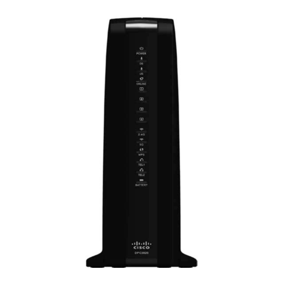
Page 21: Front Panel Description
Front Panel Description Front Panel Description The front panel of your residential gateway provides LED status indicators that indicate how well and at what state your residential gateway is operating. See Operation of Front Panel Indicators (on page 19), for more information on front panel LED status indicator functions. - Page 22 Chapter 1 Introducing the DOC SIS Wireless Residential Voice Gateway WIRELESS ON/OFF (Optional)—Press this button to activate and turn on the Wireless feature. This feature allows users to transfer data over the wireless connection. When the WIRELESS indicator is ON, it indicates that the Wireless Access Point is operational.
-
Page 23: Back Panel Description
Back Panel Description Back Panel Description The following illustration identifies the back panel components on the residential gateway. Descriptions for each component follow the illustration. Important: Do not connect your PC to both the Ethernet and USB ports at the same time. - Page 24 Chapter 1 Introducing the DOC SIS Wireless Residential Voice Gateway ETHERNET—Four RJ-45 Ethernet ports connect to the Ethernet port on your PC or your home network. RESET—A momentary pressing (1-2 seconds) of this switch restarts (power cycles) the device. Pressing and holding the switch for more than ten seconds first causes a reset-to-factory-default of all settings and then restarts (power cycles) the device.
-
Page 25: Chapter 2 Installing The Docsis Wireless Residential Voice Gateway
Chapter 2 Installing the DOCSIS Wireless Residential Voice Gateway Introduction This chapter describes how to properly install the residential gateway and to connect the residential gateway to a computer and other devices. In This Chapter Installation P reparations ..............10 ... -
Page 26: Installation Preparations
Chapter 2 Installing the D OC SIS Wireless Residential Voice Gateway Installation Preparations Before installing the residential gateway, make sure that your system meets or exceeds the requirements listed in this section. Also, make sure that you have prepared your home and home devices as described in this section. What Are the System Requirements for Internet Service? To ensure that your residential gateway operates efficiently for high-speed Internet service, you must have an Internet-capable PC, Mac, or Internet appliance equipped... - Page 27 Installation Preparations Dialing Requirements All your telephones should be set to use Dual-Tone Multi-Frequency (DTMF) dialing. Pulse dialing may not be supported by your local service provider. Telephone Wiring Requirements The residential gateway supports connecting to the interior telephone wiring as well as connecting directly to a telephone or fax machine.
- Page 28 Chapter 2 Installing the D OC SIS Wireless Residential Voice Gateway Information Your Serv ice Prov ider Needs You will need to give your service provider the following information, which is printed on the bar code label attached to the device: The Serial Number (S/N) of the residential gateway.
- Page 29 Installation Preparations Consider these recommendations: Choose a location close to your computer if you will also use the residential gateway for high-speed Internet service. Choose a location that is near an existing RF coaxial connection to eliminate the need for an additional RF coaxial outlet.
- Page 30 Chapter 2 Installing the D OC SIS Wireless Residential Voice Gateway Equipment Needed Verify that you have the following items that you will need to mount the residential gateway: Two wall anchors for #8 x 1-inch screws Two #8 x 1-inch pan head sheet metal screws ...
- Page 31 Installation Preparations Mounting the Residential Gateway on a Wall Using a drill with a 3/16-inch bit, drill two holes at the same height and 4 inches apart. Note: The preceding graphic illustrates the location of the mounting holes on the back of the residential gateway.
- Page 32 Chapter 2 Installing the D OC SIS Wireless Residential Voice Gateway WARNING: Fully charged high-capacity rechargeable batteries should be handled with care. Replace only with the battery recommended by the manufacturer. Do not disassemble it or attempt to recharge the battery outside the system. Do not crush, puncture, dispose of in a fire, short the external contacts, or expose to high temperature or immerse in water or other liquids.
-
Page 33: Install The Wireless Residential Voice Gateway
Install the Wireless Residential Voice Gateway Install the Wireless Residential Voice Gateway This section describes how to connect your residential gateway to support the services that the residential gateway offers. Important: If you have not already done so, insert the battery in the residential gateway before you mount the residential gateway on a wall (if desired) or before you install the residential gateway in your home. - Page 34 Chapter 2 Installing the D OC SIS Wireless Residential Voice Gateway Wireless: Make sure that your wireless device is powered up. You will need to associate your wireless device with the wireless residential gateway once the residential gateway is operational. Follow the directions provided for your wireless device for associating with a wireless access point.
-
Page 35: Chapter 3 Operation Of Front Panel Indicators
Chapter 3 Operation of Front Panel Indicators Introduction This section describes the behavior of the front panel indicators when the residential gateway is first powered up, during normal operations, and in special conditions. In This Chapter Initial Power Up, Calibration, and Registration (AC Power Applied) ....................20 ... -
Page 36: Initial Power Up, Calibration, And Registration (Ac Power Applied)
Chapter 3 Operation of Front Panel Indicators Initial Power Up, Calibration, and Registration (AC Power Applied) The following chart illustrates the sequence of steps and the corresponding appearance of the residential gateway front panel LED status indicators during power up, calibration, and registration on the network when AC power is applied to the residential gateway. - Page 37 Initial Power Up, Calibration, and Registration (AC Power Applied) Front Panel Data Network Requesting Request Restarting Voice Telephone Indicator Registration Telephone IP Telephone Service Registration Complete Address Provisioning File Complete POWER ONLINE ETHERNET On or Blinking On or Blinking On or Blinking On or Blinking On or Blinking On or Blinking...
-
Page 38: Normal Operations (Ac Power Applied)
Chapter 3 Operation of Front Panel Indicators Normal Operations (AC Power Applied) The following chart illustrates the appearance of the residential gateway front panel LED status indicators during normal operations when AC power is applied to the gateway. Front Panel LED Status Indicators During Normal Conditions Front Panel Indicator Normal Operations POWER... - Page 39 Normal Operations (AC Power Applied) BATTERY On – When battery is charged (Optional for Blinks – When battery charge is low some models) Off – When there is no battery in the unit Note: In addition to the status shown in the previous table, some service providers use color-coded LEDs to indicate detailed channel bonding and data link status.
-
Page 40: Special Conditions
Chapter 3 Operation of Front Panel Indicators Special Conditions The following chart describes the appearance of the residential gateway front panel LED status indicators during special conditions to show when you have been denied network access. Front Panel LED Status Indicators During Special Conditions Front Panel Indicator Network Access Denied POWER... -
Page 41: Chapter 4 Maintaining The Battery
Chapter 4 Maintaining the Battery Introduction This chapter describes how to maintain and replace the battery that is included with the residential gateway. In This Chapter Location of the Battery ...............26 Battery Maintenanc e ................27 OL-30 505 -01... -
Page 42: Location Of The Battery
Chapter 4 Maintaining the Battery Location of the Battery The following illustration shows the location of the battery. <insert bottom panel> OL-30505-01... -
Page 43: Battery Maintenance
Battery Maintenance Battery Maintenance If your residential gateway contains a battery backup feature, a high-capacity rechargeable battery provides stand-by operation in the event of an AC power failure. You can replace the battery without the use of any tools. WARNING: Fully charged high-capacity rechargeable batteries should be handled with care. - Page 44 Chapter 4 Maintaining the Battery Important: It can take as long as 24 hours for the battery to charge fully. Note: Dispose of the battery in accordance with local regulations and instructions from your service provider. Using the Wireless Residential Voice Gateway Without a Battery If you want, you can use the residential gateway without a battery.
-
Page 45: Chapter 5 Troubleshooting The Docsis Wireless Residential Voice Gateway
Chapter 5 Troubleshooting the DOCSIS Wireless Residential Voice Gateway Introduction This chapter describes the most common issues that may occur after the residential gateway is installed and provides possible solutions and tips for improved performance of the residential gateway. In This Chapter ... -
Page 46: Frequently Asked Questions
Chapter 5 Troubleshooting the D OCSIS Wireless Residential Voice Gateway Frequently Asked Questions This section provides answers to common questions about the residential gateway. How Do I Configure TCP/IP Protocol? To configure TCP/IP protocol, you need to have an Ethernet Network Interface Card (NIC) with TCP/IP communications protocol installed on your system. - Page 47 Frequently Asked Questions To get a DNS server address automatically using DHCP, click Obtain DNS server address automatically, and then click OK. To specify a DNS server address, click Use the following DNS server addresses, and then, in the Preferred DNS server and Alternate DNS server boxes, type the addresses of the primary and secondary DNS servers.
- Page 48 Chapter 5 Troubleshooting the D OCSIS Wireless Residential Voice Gateway Note: Make sure that the Load only when needed option is unchecked. Verify that the Use 802.3 option located in the upper-right corner of the TCP/IP window is unchecked. If there is a check mark in the option, uncheck the option, and then click Info in the lower-left corner.
- Page 49 Frequently Asked Questions Renew ing the IP Address on Macintosh Sy stems Close all open programs. Open your Preferences folder. Drag the tcp/ip preferences file to the Trash. Close all open windows and empty the Trash. Restart your computer. As your computer starts, simultaneously press and hold down the Command (Apple), Option, P, and R keys on your keyboard.
- Page 50 Chapter 5 Troubleshooting the D OCSIS Wireless Residential Voice Gateway How Do I Arrange for Installation? Call your service provider to inquire about professional installation. A professional installation ensures proper cable connection to the residential gateway and to your PC, and it ensures the proper configuration of all hardware and software settings. Contact your service provider for more information about installation.
-
Page 51: Common Troubleshooting Issues
Common Troubleshooting Issues Common Troubleshooting Issues This section describes common problems and offers solutions. I don't understand the front panel status indicators See Operation of Front Panel Indicators (on page 19), for more detailed information on front panel LED status indicator operation and function. The Wireless Residential Voice Gateway does not register an Ethernet connection Try one of the following solutions:... - Page 52 Chapter 5 Troubleshooting the D OCSIS Wireless Residential Voice Gateway There may be a problem with your home telephone wiring. Use a telephone and connect directly to the same RJ-11 port on the back of the unit. If the dial tone is working here but does not work at other locations in the home, a professional may need to diagnose and repair a problem with your telephone wiring.
-
Page 53: Tips For Improved Performance
Tips for Improved Performance Tips for Improved Performance If your residential gateway does not perform as expected, the following tips may help. If you need further assistance, contact your service provider. Verify that the plug to your residential gateway AC power is properly inserted ... -
Page 54: Chapter 6 Customer Information
Chapter 6 Customer Information Introduction If you have technical questions, call Cisco Services for assistance. Follow the menu options to speak with a service engineer. Access your company's extranet site to view or order additional technical publications. For accessing instructions, contact the representative who handles your account. - Page 55 Index how to access • 34 surfing while watching T V • 34 unable t o access • 32 accessing the Internet • 34 IP address, renewing • 33 accessories • 3 LEDs • 5, 20, 22, 24 battery charging • 27 location disposal •...
- Page 56 Index ventilation requirements • ix Voice settings LEDs • 5, 20, 22, 24 wall mounting instructions • 15 slots • 14 OL-30505-01...
- Page 57 Fax: +1-408 527-0883 This document includes various trademarks of Cisco Systems, Inc. Please see the Notices section of this document for a list of the Cisco Systems, Inc. trademarks used in this document. Product and service availability are subject to change without notice.
Need help?
Do you have a question about the DPC3929CM and is the answer not in the manual?
Questions and answers