Advertisement
Advertisement
Table of Contents

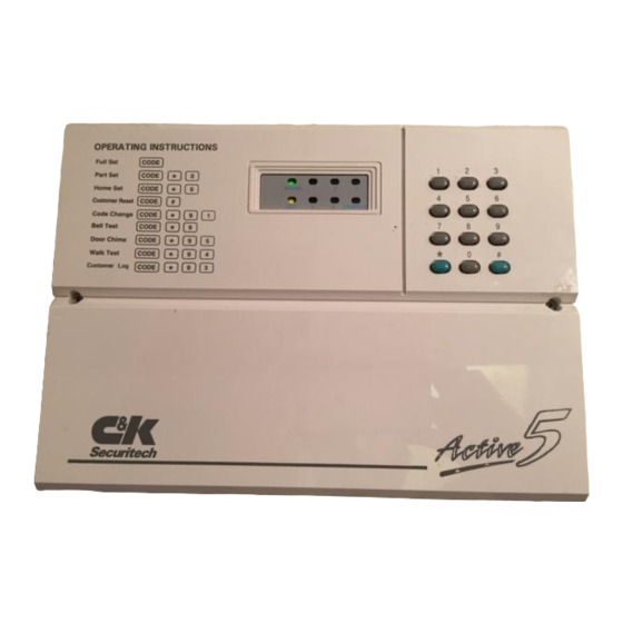
Summary of Contents for C & K Systems ACTIVE 5
- Page 1 ACTIVE 5 ENGINEERING MANUAL C & K Systems Ltd C031-066 Issue 3...
-
Page 2: System Planning
& options before attempting to program. The Active 5 should ideally be installed out of sight but remain accessible. The panel, and its keypads (if used) should be mounted within the area covered by the alarm system. -
Page 3: Factory Defaults
FACTORY DEFAULTS User / Customer Code 1 1234 Engineer Code 7890 Circuit 1 Personal Attack (PA) Circuit 2 Alarm circuit Circuit 3 Alarm circuit isolated in home set Circuit 4 Alarm circuit with walkthrough Circuit 5 Entry / Exit circuit Full set exit time 30 seconds Night set exit time... -
Page 4: Wiring The Control Panel
Battery connection. The Active 5 requires a standby battery to be fitted to provide power in the event of mains failure. A sealed lead acid battery should be fitted (maximum 6 Ah). Detector circuits Connections are provided for up to five detector circuits on which normally closed detection devices should be used. - Page 5 PIR Latch Line (L+) In the event of two or more PIR detectors being fitted to any zone, latching detectors can be used. The 'L+' connection provides this function. It is low (0V) when unset and high (12 v) when set. Detector reset (ID) Some detectors require the removal of power to reset (e.g.
-
Page 6: Setting Options
3) Individual keypads do not need to be identified to the system. (i.e. addressed) DIAGRAM C SETTING OPTIONS. The Active 5 can be operated with a remote keyswitch or remote keypad. Three methods of setting may be used. Timed exit... -
Page 7: Alarm Outputs
LINE FAULT INPUT If you are using the Active 5X which is a comms version of the Active 5 control panel, you will be able to utilise the line fault terminals. These are a pair of contacts which should be connected to a relay output of a communicator. -
Page 8: Initial Power-Up
INITIAL POWER UP NOTE The lid should be kept off the main control panel. The keypad tamper may also be used to enter engineer mode. Switch the mains supply on, the internal sounder will start. Enter 1 2 3 4 followed by # button, this will silence the sounder and the TAMPER LED will then flash. -
Page 9: Option 3-0 Exit Time
5-105 OPTION 3-0 EXIT TIME Seconds. DEFAULT. 30 secs. Enter 3-0 - LED 6 will light up. This has been preset for factory default - at 30 seconds. A new time may be programmed by entering the relevant keys which total up to make the required time multiplied by 5. Once program is set press * to confirm. - Page 10 CIRCUIT PROGRAMMING MATRIX REFERENCE GUIDE LED 1 LED 2 LED 3 LED 4 LED 5 LED 6 TAMPER LED ISOLATE IN ISOLATE IN WALK THROUGH CHIME ISOLATE ALARM HOME SET NIGHT SET ENTRY ROUTE PERMIT WALK THROUGH CHIME ISOLATE FULL SET NIGHT SET ENTRY ROUTE PERMIT...
- Page 11 24 HOUR ZONE. This zone type is active 24 hours a day irrespective of whether the control panel is armed or disarmed. In the armed condition it will signal a full alarm if triggered. In the disarmed condition it will give a local internal alarm warning only.
- Page 12 WARNING TONE . A 24 hour zone option which, following and alarm in the day condition, allows the internal alarm sounder tone to be changed to a rapid beeping. This will give a differential to other day time alarms. EXAMPLE TO PROGRAM ZONE 1 ENTER 4-1.
- Page 13 7-X OPTIONS. The 7 Options controls how the panel responds to given criteria. Some options ⊗. only apply if a communicator is fitted (Active 5X only) these are marked with a OPTION 7-0. NIGHT SET OPTIONS. 70-1 Night set disable 70-2 Disable bells in Night set 70-3 ⊗...
- Page 14 2 Stage Communicator output 74-3 10 minute auto isolate of an open zone when set. 74-4 BLOCKSCHLOSS - German Setting Method. BELLBOX CONNECTIONS LEFT HAND RIGHT HAND ACTIVE 5 PANEL BELL+ TAMPER TAMPER SONADE 2000 STROBE- FLASHGUARD XL+ STROBE- SIREN-...
- Page 15 ZONE ZONE USE / LOCATION RESISTANCE KEYS ENTERED Ω Ω Ω Ω Ω Ω Ω Ω Ω Ω TIMER VALUE KEYS ENTERED FULL SECONDS NIGHT SECONDS EXT SOUNDER MINUTES DELAY MINUTES TICK BOX CHECKED NIGHT SET OPTIONS HOME SET OPTIONS ENGINEER OPTIONS LINE FAULT OPTIONS EUROPEAN OPTIONS...
Need help?
Do you have a question about the ACTIVE 5 and is the answer not in the manual?
Questions and answers