
Related Manuals for IBASE Technology IB895


Summary of Contents for IBASE Technology IB895
- Page 1 IB895 Intel Cedarview-D or ® Cedarview-M / NM10 3.5” Disk Size SBC USER’S MANUAL Version 1.1A...
- Page 2 Intel and Intel® Sandy Bridge DC/QC Processor are registered trademarks of Intel Corporation. Microsoft Windows is a registered trademark of Microsoft Corporation. Winbond a registered trademark of Winbond Electronics Corporation. All other product names or trademarks are properties of their respective owners. IB895 User’s Manual...
-
Page 3: Table Of Contents
Table of Contents Introduction ............1 Product Description............. 1 Checklist................2 IB895 Specifications ............3 Board Dimensions ............... 4 Installations ............5 Installing the Memory ............6 Setting the Jumpers ............. 7 Connectors on IB895............11 BIOS Setup ............19 Drivers Installation ........39 Intel Chipset Software Installation Utility...... - Page 4 This page is intentionally left blank. IB895 User’s Manual...
-
Page 5: Introduction
INTRODUCTION Introduction Product Description ® The IB895 is a 3.5-inch single board computer based on the Intel Atom Cedarview chipset. The Cedar Trail is a platform that uses the Intel Cedarview-D or Cedarview -M Processor and Intel NM10 Express Chipset family in the desktop platforms. -
Page 6: Checklist
INTRODUCTION Checklist Your IB895 package should include the items listed below. The IB895 Embedded Flex Motherboard This User’s Manual 1 CD containing chipset drivers and flash memory utility IB895 User’s Manual... -
Page 7: Ib895 Specifications
IB895 [default silk screen model # on PCB] IB895N(N2600 onboard) Form Factor 3.5” Intel® Atom DC D2550 / 1MB cache / 1.86 GHz [TDP=10W] (IB895) Type/Speed Intel® Atom DC N2600 / 1MB cache / 1.60 GHz [TDP=3.5W] (IB895N) Package = FCBGA437 [ 22 mm x 22 mm] ; Cores / Threads = 2 / 4 ®... -
Page 8: Board Dimensions
+12V ~ +24V DC-in Connector - i-Smart function (TI MSP430G2433 MCU) Others - AT24C02C EEPROM [SO8 type] via SMbus (Optional) OS Support - Windows 7 (32-bit only) - Linux RoHS 102mm x 147mm Board Size Board Dimensions IB895 User’s Manual... -
Page 9: Installations
INSTALLATIONS Installations This section provides information on how to use the jumpers and connectors on the IB895 in order to set up a workable system. The topics covered are: Installing the Memory ................6 Setting the Jumpers................7 Connectors on IB895................11... -
Page 10: Installing The Memory
The IB895 board supports one DDR3 memory socket for a maximum total memory of 2GB or 4GB DDR3 memory type. Note: IB895 with Intel Atom DC D2550 supports up to 4GB and IB895N with Intel Atom DC N2600 supports up to 2GB. -
Page 11: Setting The Jumpers
INSTALLATIONS Setting the Jumpers Jumpers are used on IB895 to select various settings and features according to your needs and applications. Contact your supplier if you have doubts about the best configuration for your needs. The following lists the connectors on IB895 and their respective functions. -
Page 12: Jumper Locations On Ib895
INSTALLATIONS Jumper Locations on IB895 Jumpers on IB895 ................Page JP2: Clear CMOS Contents ..............9 JP3: BL Voltage Setting ................ 9 JP5: COM1 RS232 RI/+5V/+12V Power Setting........9 JP6: LVDS Panel Power Selection ............9 JP7: BL_ADJ_LEVEL Setting ............10 JP8: Factory use only................ -
Page 13: Jp2: Clear Cmos Contents
Pin 5-6 +12V(Default) Short/Closed JP5: COM1 RS232 RI/+5V/+12V Power Setting Setting Function Pin 1-2 +12V Short/Closed Pin 3-4 Short/Closed Pin 5-6 Short/Closed JP6: LVDS Panel Power Selection Setting Panel Voltage Pin 1-2 3.3V (default) Short/Closed Pin 2-3 Short/Closed IB895 User’s Manual... -
Page 14: Jp7: Bl_Adj_Level Setting
1280*768 18bit 1ch 1280*800 18bit 1ch 1280*960 18bit 1ch 1280*1024 24bit 2ch 1366*768 18bit 1ch 1366*768 24bit 1ch 1440*900 24bit 2ch 1440*1050 24bit 2ch 1600*900 24bit 2ch 1680*1050 24bit 2ch 1600*1200 24bit 2ch 1920*1080 24bit 2ch 1920*1200 24bit 2ch IB895 User’s Manual... -
Page 15: Connectors On Ib895
INSTALLATIONS Connectors on IB895 Connector Locations on IB895............12 CN4, CN5: Gigabit LAN (Intel 82583V)..........13 CN6: USB 1/2 Connector..............13 CN7: VGA DVI-I Connector .............. 13 CN8: DB9 Connector ................13 CN1, CN3: SATA Connector.............. 14 CN2: LCD Backlight Connector ............14 J1: Board Input Power Connector ............ -
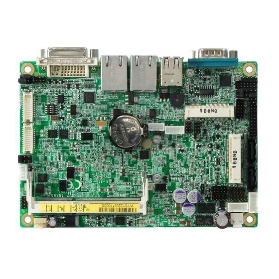
Page 16: Connector Locations On Ib895
INSTALLATIONS Connector Locations on IB895 IB895 User’s Manual... -
Page 17: Cn4, Cn5: Gigabit Lan (Intel 82583V)
CTS, Clear to send DTR, Data terminal ready RI, Ring indicator GND, ground Not Used COM1 is jumper-less for RS-232, RS-422 and RS-485 and configured with BIOS Selection. Pin # Signal Name RS-232 R2-422 RS-485 DATA- DATA+ Ground Ground Ground IB895 User’s Manual... -
Page 18: Cn1, Cn3: Sata Connector
J2, J3: SATA HDD Power Connector Pin # Signal Name Ground Ground +12V J4: Debug 80 Port Connector (factory use only) J5: Digital I/O Connector Signal Name Signal Name OUT3 OUT1 OUT2 OUT0 J6: SPI Flash Connector (factory use only) IB895 User’s Manual... -
Page 19: J7: Keyboard & Mouse Connector (Df11 Connector)
SATA. J11: Smart Battery Interface Connector Pin # Signal Name EXTSMI Ground DATA J12, J13: USB3/4/5/6 Connector Signal Name Pin # Pin # Signal Name Ground Ground J14: MCU Flash Connector (factory use only) IB895 User’s Manual... -
Page 20: J15: Com3, Com4 Serial Port (Df11 Connector)
CTS, Clear to send RI, Ring indicator Not Used J17: Mini PCIE Connector J18: Audio Connector (DF11 Connector) Signal Name Pin # Pin # Signal Name LINEOUT_R LINEOUT_L Ground JD_FRONT LINEIN_R LINEIN_L Ground JD_LINEIN MIC-R MIC_L Ground JD_MIC1 IB895 User’s Manual... -
Page 21: J22: Amplify Connector
OUTL+ OUTL- OUTR- OUTR+ J23: LVDS EEPROM Flash Connector (factory use only) CH1, CH2: LVDS Connectors Signal Name Pin # Pin # Signal Name ENABLE LCD_PWR CLK+ CLK- LD2+ LD2- LD3+ LD3- LCD_PWR LD1+ LD1- LD0+ LD0- IB895 User’s Manual... -
Page 22: Jp1: Front Panel Connector
Reset Switch: Pins 7 and 8 The reset switch allows the user to reset the system without turning the main power switch off and then on again. Orientation is not required when making a connection to this header. IB895 User’s Manual... -
Page 23: Bios Setup
The topics covered in this chapter are as follows: BIOS Introduction ..................20 BIOS Setup ....................20 Advanced Settings ..................22 Chipset Settings .................... 31 Boot Settings ....................36 Security Settings ................... 37 Save & Exit Settings ..................38 IB895 User’s Manual... -
Page 24: Bios Introduction
<PgUp> and <PgDn> keys to change entries, <F1> for help and <Esc> to quit. When you enter the Setup utility, the Main Menu screen will appear on the screen. The Main Menu allows you to select from various setup functions and exit choices. IB895 User’s Manual... - Page 25 Changing the defaults could cause the system to become unstable and crash in some cases. System Date Set the Date. Use Tab to switch between Data elements. System Time Set the Time. Use Tab to switch between Data elements. IB895 User’s Manual...
-
Page 26: Advanced Settings
► H/W Monitor Enter: Select Change Opt ► PPM Configuration F1: General Help F2: Previous Values F3: Optimized Default F4: Save & EXIT ESC: Exit Launch PXE OpROM Enable or Disable Boot Option for Legacy Network Devices. IB895 User’s Manual... -
Page 27: Pci Subsystem Settings
Value to be programmed into PCI Latency Timer Register. VGA Palette Snoop Enables or Disables VGA Palette Registers Snooping. PERR# Generation Enables or Disables PCI Device to Generate PERR#. SERR# Generation Enables or Disables PCI Device to Generate SERR#. IB895 User’s Manual... -
Page 28: Acpi Settings
Enable ACPI Auto Configuration Disabled ↑↓ Select Item Enter: Select Change Opt F1: General Help F2: Previous Values F3: Optimized Default F4: Save & EXIT ESC: Exit Enabled ACPI Auto Configuration Enables or Disables BIOS ACPI Auto Configuration. IB895 User’s Manual... -
Page 29: Wake On Ring
Enter: Select Change Opt F1: General Help F2: Previous Values F3: Optimized Default F4: Save & EXIT ESC: Exit Wake on Ring The options are Disabled and Enabled. Wake on PCIE PME The options are Disabled and Enabled. IB895 User’s Manual... -
Page 30: Cpu Configuration
XD can prevent certain classes of malicious buffer overflow attacks when combined with a supporting OS (Windows Server 2003 SP1, Windows XP SP2, SuSE Linux 9.2, Re33dHat Enterprise 3 Update 3.) Limit CPUID Maximum Disabled for Windows XP. IB895 User’s Manual... -
Page 31: Ide Configuration
SATA Controller(s) Enabled F1: General Help F2: Previous Values Configure SATA as F3: Optimized Default F4: Save & EXIT ESC: Exit SATA Controller(s) Enable / Disable Serial ATA Controller. Configure SATA as (1) IDE Mode. (2) AHCI Mode. IB895 User’s Manual... -
Page 32: Usb Configuration
Maximum time the device will take before it properly reports itself to the Host Controller. ‘Auto’ uses default value: for a Root port it is 100ms, for a Hub port the delay is taken from Hub descriptor. IB895 User’s Manual... -
Page 33: Super Io Configuration
F4: Save & EXIT ESC: Exit Temperatures/Voltages These fields are the parameters of the hardware monitoring function feature of the motherboard. The values are read-only values as monitored by the system and show the PC health status. IB895 User’s Manual... -
Page 34: Ppm Configuration
Main Chipset Boot Security Save & Exit PPM Configuration → ← Select Screen EIST Enabled ↑↓ Select Item Enter: Select Change Opt F1: General Help F2: Previous Values F3: Optimized Default F4: Save & EXIT ESC: Exit IB895 User’s Manual... -
Page 35: Chipset Settings
Select Screen ↑↓ Select Item ************Memory Information************ Enter: Select Memory Frequency 1067 MHz(DDR3) Change Opt Total Memory 2048 MB F1: General Help DIMM#1 2048 MB F2: Previous Values F3: Optimized Default F4: Save & EXIT ESC: Exit IB895 User’s Manual... -
Page 36: Mrc Fast Boot
Select Screen ↑↓ Select Item Enter: Select Change Opt F1: General Help F2: Previous Values F3: Optimized Default F4: Save & EXIT ESC: Exit IGFX-Boot Type Select the video Device which will be activated during POST . IB895 User’s Manual... - Page 37 PCI-Exp. High Priority Port The options are Disabled, Port1, Port2, Port3, and Port4. High Precision Event Timer Configuration Enable/or Disable the High Precision Event Timer. SLP_S4 Assertion Stretch Enable Select a minimum assertion width of the SLP_S4# signal. IB895 User’s Manual...
- Page 38 Port 0 IOxAPIC Disabled ↑↓ Select Item Automatic ASPM Manual Enter: Select ASPM L0s Root Port Only Change Opt ASPM L1 Enabled F1: General Help F2: Previous Values F3: Optimized Default F4: Save & EXIT ESC: Exit IB895 User’s Manual...
- Page 39 → ← PCI Express Port 3 Auto Select Screen Port 0 IOxAPIC Disabled ↑↓ Select Item Automatic ASPM Auto Enter: Select Change Opt F1: General Help F2: Previous Values F3: Optimized Default F4: Save & EXIT ESC: Exit IB895 User’s Manual...
-
Page 40: Boot Settings
ALWAYS – do not allow disabling GA20; this option is useful when any RT code is executed above 1MB. Option ROM Messages Set display mode for Option ROM. Options: Force BIOS; Keep Current. Interrupt 19 Capture Enable: Allows Option ROMs to trap Int 19. CSM Support Enables/Disables/Auto CSM Support. IB895 User’s Manual... -
Page 41: Security Settings
Setup. In Setup the User will have Change Opt Administrator rights F1: General Help F2: Previous Values Administrator Password F3: Optimized Default User Password F4: Save & EXIT ESC: Exit Administrator Password Set Setup Administrator Password. User Password Set User Password. IB895 User’s Manual... -
Page 42: Save Changes And Exit
Discard Changes done so far to any of the setup options. Restore Defaults Restore/Load Defaults values for all the setup options. Save as User Defaults Save the changes done so far as User Defaults. Restore User Defaults Restore the User Defaults to all the setup options. IB895 User’s Manual... -
Page 43: Drivers Installation
VGA Drivers Installation ..............41 Realtek HD Audio Driver Installation..........42 LAN Drivers Installation ..............43 IMPORTANT NOTE: After installing your Windows operating system, you must install first the Intel Chipset Software Installation Utility before proceeding with the drivers installation. IB895 User’s Manual... -
Page 44: Intel Chipset Software Installation Utility
4. Click Yes to accept the software license agreement and proceed with the installation process. 5. On the Readme File Information screen, click Next to continue the installation. 6. The Setup process is now complete. Click Finish to restart the computer and for changes to take effect. IB895 User’s Manual... -
Page 45: Vga Drivers Installation
5. On the Readme File Information screen, click Next to continue the installation of the Intel® Graphics Media Accelerator Driver. 6. On Setup Progress screen, click Next to continue. 7. Setup complete. Click Finish to restart the computer and for changes to take effect. IB895 User’s Manual... -
Page 46: Realtek Hd Audio Driver Installation
Realtek HD Audio Driver Installation 1. Click Realtek High Definition Audio Driver. 2. On the Welcome to the InstallShield Wizard screen, click Next to proceed with and complete the installation process. 3. Restart the computer when prompted. IB895 User’s Manual... -
Page 47: Lan Drivers Installation
5. Click the checkbox for Drivers in the Setup Options screen to select it and click Next to continue. 6. When the Ready to Install the Program screen appears, click Install to continue. 7. When InstallShield Wizard is complete, click Finish. IB895 User’s Manual... -
Page 48: Appendix
00AC-00AD Programmable interrupt controller 00B0-00B1 Programmable interrupt controller 00B4-00B5 Programmable interrupt controller 00B8-00B9 Programmable interrupt controller 00BC-00BD Programmable interrupt controller 00C0-00DF Direct memory access controller 00F0-00F0 Numeric data processor 02E8-02EF Communications Port (COM4) 02F8-02FF Communications Port (COM2) IB895 User’s Manual... - Page 49 Intel(R) N10/ICH7 Family Serial ATA F0C0-F0C7 Storage Controller - 27C0 Intel(R) N10/ICH7 Family Serial ATA F0D0-F0D3 Storage Controller - 27C0 F0E0-F0E7 Intel(R) N10/ICH7 Family Serial ATA Storage Controller - 27C0 F0F0-F0F7 Intel(R) Graphics Media Accelerator 3600 Series IB895 User’s Manual...
-
Page 50: Interrupt Request Lines (Irq)
Intel(R) 82583V Gigabit Network Connection #2 IRQ 4294967291 Intel(R) Graphics Media Accelerator 3600 Series IRQ 4294967292 IRQ 4294967293 Intel(R) N10/ICH7 Family PCI Express Root Port - 27D2 IRQ 4294967294 Intel(R) N10/ICH7 Family PCI Express Root Port - 27D0 IB895 User’s Manual... -
Page 51: Digital I/O Sample Code
(W627UHG_BASE) #define W627UHG_DATA_PORT (W627UHG_BASE+1) //--------------------------------------------------------------------------- #define W627UHG_REG_LD 0x07 //--------------------------------------------------------------------------- #define W627UHG_UNLOCK 0x87 #define W627UHG_LOCK 0xAA //--------------------------------------------------------------------------- unsigned int Init_W627UHG(void); void Set_W627UHG_LD( unsigned char); void Set_W627UHG_Reg( unsigned char, unsigned char); unsigned char Get_W627UHG_Reg( unsigned char); //--------------------------------------------------------------------------- #endif //__W627UHG_H IB895 User’s Manual... - Page 52 (ucDid == 0xA2) //W83627UHG?? goto Init_Finish; } W627UHG_BASE = 0x00; result = W627UHG_BASE; Init_Finish: return (result); //--------------------------------------------------------------------------- void Unlock_W627UHG (void) outportb(W627UHG_INDEX_PORT, W627UHG_UNLOCK); outportb(W627UHG_INDEX_PORT, W627UHG_UNLOCK); //--------------------------------------------------------------------------- void Lock_W627UHG (void) outportb(W627UHG_INDEX_PORT, W627UHG_LOCK); //--------------------------------------------------------------------------- void Set_W627UHG_LD( unsigned char LD) IB895 User’s Manual...
- Page 53 LD); Lock_W627UHG(); //--------------------------------------------------------------------------- void Set_W627UHG_Reg( unsigned char REG, unsigned char DATA) Unlock_W627UHG(); outportb(W627UHG_INDEX_PORT, REG); outportb(W627UHG_DATA_PORT, DATA); Lock_W627UHG(); //--------------------------------------------------------------------------- unsigned char Get_W627UHG_Reg(unsigned char REG) unsigned char Result; Unlock_W627UHG(); outportb(W627UHG_INDEX_PORT, REG); Result = inportb(W627UHG_DATA_PORT); Lock_W627UHG(); return Result; //--------------------------------------------------------------------------- IB895 User’s Manual...
- Page 54 Winbond 83627UHG, program abort.\n"); return(1); Dio5Initial(); //for GPIO50..57 Dio5SetDirection(0x0F); //GP50..53 = input, GP54..57=output printf("Current DIO direction = 0x%X\n", Dio5GetDirection()); printf("Current DIO status = 0x%X\n", Dio5GetInput()); printf("Set DIO output to high\n"); Dio5SetOutput(0x0F); printf("Set DIO output to low\n"); Dio5SetOutput(0x00); return 0; IB895 User’s Manual...
- Page 55 Dio5SetDirection(unsigned char NewData) //NewData : 1 for input, 0 for output Set_W627UHG_LD(0x08); //switch to logic device 8 Set_W627UHG_Reg(0xE0, NewData); //--------------------------------------------------------------------------- unsigned char Dio5GetDirection(void) unsigned char result; Set_W627UHG_LD(0x08); //switch to logic device 8 result = Get_W627UHG_Reg(0xE0); return (result); //--------------------------------------------------------------------------- IB895 User’s Manual...
-
Page 56: Watchdog Timer Configuration
= W627UHG_BASE; ucDid = Get_W627UHG_Reg(0x20); if (ucDid == 0xA2) //W83627UHG?? goto Init_Finish; } W627UHG_BASE = 0x2E; result = W627UHG_BASE; ucDid = Get_W627UHG_Reg(0x20); if (ucDid == 0xA2) //W83627UHG?? goto Init_Finish; } W627UHG_BASE = 0x00; result = W627UHG_BASE; IB895 User’s Manual... - Page 57 LD); Lock_W627UHG(); //--------------------------------------------------------------------------- void Set_W627UHG_Reg( unsigned char REG, unsigned char DATA) Unlock_W627UHG(); outportb(W627UHG_INDEX_PORT, REG); outportb(W627UHG_DATA_PORT, DATA); Lock_W627UHG(); //--------------------------------------------------------------------------- unsigned char Get_W627UHG_Reg(unsigned char REG) unsigned char Result; Unlock_W627UHG(); outportb(W627UHG_INDEX_PORT, REG); Result = inportb(W627UHG_DATA_PORT); Lock_W627UHG(); return Result; //--------------------------------------------------------------------------- IB895 User’s Manual...
- Page 58 (W627UHG_BASE) #define W627UHG_DATA_PORT (W627UHG_BASE+1) //--------------------------------------------------------------------------- #define W627UHG_REG_LD 0x07 //--------------------------------------------------------------------------- #define W627UHG_UNLOCK 0x87 #define W627UHG_LOCK 0xAA //--------------------------------------------------------------------------- unsigned int Init_W627UHG(void); void Set_W627UHG_LD( unsigned char); void Set_W627UHG_Reg( unsigned char, unsigned char); unsigned char Get_W627UHG_Reg( unsigned char); //--------------------------------------------------------------------------- #endif //__W627UHG_H IB895 User’s Manual...
- Page 59 ..........printf("Can not detect Winbond 83627UHG, program abort.\n"); ............................return(1); WDTInitial(); WDTEnable(10); WDTDisable(); return 0; //--------------------------------------------------------------------------- void WDTInitial(void) unsigned char bBuf; Set_W627UHG_LD(0x08); ..............//switch to logic device 8 bBuf = Get_W627UHG_Reg(0x30); bBuf &= (~0x01); Set_W627UHG_Reg(0x30, bBuf);..............//Enable WDTO //--------------------------------------------------------------------------- void WDTEnable(unsigned char NewInterval) IB895 User’s Manual...
- Page 60 Set_W627UHG_Reg(0x30, 0x01); ................ //enable timer bBuf = Get_W627UHG_Reg(0xF5); bBuf &= (~0x08); Set_W627UHG_Reg(0xF5, bBuf); ............//count mode is second Set_W627UHG_Reg(0xF6, NewInterval); ..............//set timer //--------------------------------------------------------------------------- void WDTDisable(void) Set_W627UHG_LD(0x08);......................Set_W627UHG_Reg(0xF6, 0x00); ............//clear watchdog timer Set_W627UHG_Reg(0x30, 0x00); .............. //watchdog disabled //--------------------------------------------------------------------------- IB895 User’s Manual...
Need help?
Do you have a question about the IB895 and is the answer not in the manual?
Questions and answers