
Related Manuals for IBASE Technology IB897


Summary of Contents for IBASE Technology IB897
- Page 1 IB897 Intel Atom E3800 SoC Series ® 3.5” Disk Size SBC USER’S MANUAL Version 1.0...
- Page 2 Intel and Atom are registered trademarks of Intel Corporation. Microsoft Windows is a registered trademark of Microsoft Corporation. Nuvoton is a registered trademark of Winbond Electronics Corporation. All other product names or trademarks are properties of their respective owners. IB897 User’s Manual...
-
Page 3: Table Of Contents
Table of Contents Introduction ............1 Product Description............. 1 Specifications ..............2 Checklist ................3 Board Dimensions for [IB897-I45/I27/I15] ......4 Board Dimensions for [IB897-I45P/I27P/I15P] ....4 Installations ............5 Installing the Memory ............6 Setting the Jumpers ............. 7 Connectors on IB897 ............ - Page 4 This page is intentionally left blank. IB897 User’s Manual...
-
Page 5: Introduction
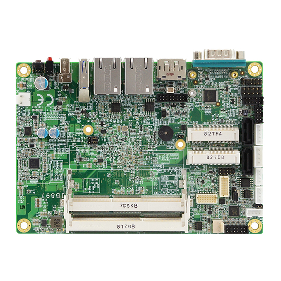
INTRODUCTION Introduction Product Description ® Intel Atom IB897 is a 3.5-inch single board computer based on the E3800 series processors. It supports two DDR3L (1.35V) SODIMM sockets for a maximum memory capacity of 8GB. ® IB897 features the Intel Gen7 w/4EUs graphics engines and has both CRT and DisplayPort video display interface, and 24-bit LVDS dual channel interface with the use of the NXP PTN3460 device. -
Page 6: Specifications
Intel® Atom SoC integrated memory controller Support DDR3L (1.35V only), Non-ECC memory only 2 x DDR3 SO-DIMM socket [IB897-I45_P/IB897-I27_P], 8GB max. 1 x DDR3 SO-DIMM socket [IB897-I15_P], 4GB max. Intel® Gen7 w/4 EUs graphics engines DisplayPort x 1 [Support to 2560x1200@60Hz]... -
Page 7: Checklist
INTRODUCTION Checklist Your IB897 package should include the items listed below. The IB897 SBC This User’s Manual 1 CD containing chipset drivers and flash memory utility IB897 User’s Manual... -
Page 8: Board Dimensions For [Ib897-I45/I27/I15]
INTRODUCTION Board Dimensions for [IB897-I45/I27/I15] Board Dimensions for [IB897-I45P/I27P/I15P] IB897 User’s Manual... -
Page 9: Installations
INSTALLATIONS Installations This section provides information on how to use the jumpers and connectors on the IB897 in order to set up a workable system. The topics covered are: Installing the Memory ................6 Setting the Jumpers ................7 Connectors on IB897 ................11... -
Page 10: Installing The Memory
INSTALLATIONS Installing the Memory The IB897 board supports TWO DDR3L memory socket for a maximum total memory of 8GB DDR3L memory type. Installing and Removing Memory Modules To install the DDR3L modules, locate the memory slot on the board and perform the following steps: 1. -
Page 11: Setting The Jumpers
INSTALLATIONS Setting the Jumpers Jumpers are used on IB897 to select various settings and features according to your needs and applications. Contact your supplier if you have doubts about the best configuration for your needs. The following lists the connectors on IB897 and their respective functions. -
Page 12: Jumper Locations On Ib897
INSTALLATIONS Jumper Locations on IB897 [IB897-I45/I27/I15] [IB897-I45P/I27P/I15P] IB897 User’s Manual... -
Page 13: Jp2: Lvds Panel Brightness Control Selection
INSTALLATIONS JP2: LVDS Panel Brightness Control Selection Brightness Control (PWM mode) Open 3.3V Close 5V(Default) J5: LVDS Panel Power Selection Setting Panel Voltage Pin 1-2 3.3V (default) Short/Closed Pin 2-3 Short/Closed IB897 User’s Manual... -
Page 14: Jp5: Clear Me Contents
INSTALLATIONS JP5: Clear ME Contents Setting Function Pin 1-2 Normal Short/Closed Pin 2-3 Clear ME Short/Closed REGISTER JP6: Clear CMOS Contents Setting Function Pin 1-2 Normal Short/Closed Pin 2-3 Clear CMOS Short/Closed IB897 User’s Manual... -
Page 15: Connectors On Ib897
CN8: DB9 Connector (COM1) ............14 CN9: Micro SD (3.3V) Connector ............14 SW1: Power Switch [For IB897-I45/I27/I15] ........14 LED1: Power LED and HDD LED Connector [For IB897-I45/I27/I15] ..15 CN1: SATAII /share mSATA/ Connectors .......... 16 CN2: SATAII Connectors ..............16 SYS_FAN1: SYSTEM Fan Power Connector ........ -
Page 16: Connector Locations On Ib897-I45/I27/I15
INSTALLATIONS Connector Locations on IB897-I45/I27/I15 Connector Locations on IB897-I45P/I27P/I15P IB897 User’s Manual... -
Page 17: Cn3: Usb3.0 Connector
INSTALLATIONS Bottom side CN3: USB3.0 Connector CN4, CN5: Gigabit LAN Connector CN4: Intel® I210IT Connector CN5: Intel® I210IT Connector CN6: USB2.0 Connector CN7: DP Connector IB897 User’s Manual... -
Page 18: Cn8: Db9 Connector (Com1)
COM1 is jumper-less for RS-232, RS-422 and RS-485 and is to be configured with BIOS Selection. Pin # Signal Name RS-232 R2-422 RS-485 DATA- DATA+ Ground Ground Ground CN9: Micro SD (3.3V) Connector SW1: Power Switch [For IB897-I45/I27/I15] IB897 User’s Manual... -
Page 19: Led1: Power Led And Hdd Led Connector [For Ib897-I45/I27/I15]
INSTALLATIONS LED1: Power LED and HDD LED Connector [For IB897-I45/I27/I15] 2x2 Pin-header (2.54mm) [For IB897-I45P/I27P/I15P] The green LED at the bottom is power LED. The red LED on top is the HDD LED. Signal Name Pin # Pin # Signal Name... -
Page 20: Cn1: Sataii /Share Msata/ Connectors
INSTALLATIONS CN1: SATAII /share mSATA/ Connectors CN2: SATAII Connectors SYS_FAN1: SYSTEM Fan Power Connector Pin # Signal Name Ground +12V(500mA) Rotation detection IB897 User’s Manual... -
Page 21: J1: Audio Connector (Df11-12Dp-2Dsa)
JD_FRONT LINEIN_R LINEIN_L Ground JD_LINEIN MIC-R MIC_L Ground JD_MIC1 J2: Amplify Connector (JST B4B-PH-K-S ) Pin # Signal Name OUTL+ OUTL- OUTR- OUTR+ J7: DDR3L SO-DIMM(CH-A) Sockets ** Please note CH-A must be installed for booting up** IB897 User’s Manual... -
Page 22: J3: Ddr3L So-Dimm(Ch-B) Sockets
J4, J6: LVDS Connectors, (DF20G-20DP-1V) J4: First Channel LVDS J6: Second Channel LVDS Signal Name Pin # Pin # Signal Name TX0N TX0P Ground Ground TX1N TX1P Ground Ground TX2N TX2P Ground Ground CLKN CLKP Ground Ground TX3N TX3P Power(1A) Power IB897 User’s Manual... -
Page 23: J9: Mcu Flash Connector (Factory Use Only)
INSTALLATIONS J9: MCU Flash Connector (factory use only) J10: SATA HDD Power Connectors(JST B4B-XH-A) Pin # Signal Name +5V(1A) Ground Ground +12V(1A) IB897 User’s Manual... -
Page 24: J11: Smart Battery(Jst B5B-Ph-K-S )
INSTALLATIONS J11: Smart Battery(JST B5B-PH-K-S ) Pin # Signal Name RST# ICHSWI# Ground SMB_DATA SMB_CLK J12: Mini PCIE Connector (share mSATA) J13: Mini PCIE Connector (Half Size) IB897 User’s Manual... -
Page 25: J14: Usb 2.0 Connector(Df11-8Dp-2Dsa)
Pin # Pin # Signal Name DCD, Data carrier detect RXD, Receive data TXD, Transmit data Data terminal ready GND, ground DSR, Data set ready RTS, Request to send CTS, Clear to send RI, Ring indicator Not Used IB897 User’s Manual... -
Page 26: J16: Vga Connector (Df11-16Dp-2Dsa)
J16: VGA Connector (DF11-16DP-2DSA) Signal Name Pin # Pin # Signal Name Ground Green Blue DDCDATA H_SYNC V_SYNC DDCCLK N.C. J17: Digital I/O(signal level 5V)Connector(2.54mm) Signal Name Pin # Pin # Signal Name VCC(500mA) OUT3 OUT1 OUT2 OUT0 IB897 User’s Manual... -
Page 27: J18: Board Input Power Connector(Hk_Wafer396-2S-Wv )
INSTALLATIONS J18: Board Input Power Connector(HK_WAFER396-2S-WV ) Pin # Signal Name +9V to +30V(10A) J19: Reset Switch(2mm) Pin # Signal Name Reset Switch Ground J20: Power Switch(2mm) Pin # Signal Name Power Switch Ground IB897 User’s Manual... -
Page 28: Jp3: Lcd Backlight Connector(Jst B4B-Ph-K-S )
INSTALLATIONS JP3: LCD Backlight Connector(JST B4B-PH-K-S ) Pin # Signal Name +12V(1A) Backlight Enable Brightness Control Ground IB897 User’s Manual... -
Page 29: Jp4: Spi Flash Connector (Factory Use Only)
INSTALLATIONS JP4: SPI Flash Connector (factory use only) JP7: Factory use only JP8: Debug 80 Port Connector (factory use only) IB897 User’s Manual... - Page 30 INSTALLATIONS This page is intentionally left blank. IB897 User’s Manual...
-
Page 31: Bios Setup
BIOS Introduction ................28 BIOS Setup ..................28 Main Settings ..................26 Advanced Settings ................30 Chipset Settings ................... 38 Security Settings .................. 39 Boot Settings..................40 Save & Exit Settings ................41 Additional Information about OS Installation ........34 IB897 User’s Manual... -
Page 32: Bios Introduction
These defaults have been carefully chosen by both AMI and your system manufacturer to provide the absolute maximum performance and reliability. Changing the defaults could cause the system to become unstable and crash in some cases. IB897 User’s Manual... -
Page 33: Main Settings
F3: Optimized Default F4: Save ESC: Exit System Language Choose the system default language. System Date Set the Date. Use Tab to switch between Data elements. System Time Set the Time. Use Tab to switch between Data elements. IB897 User’s Manual... -
Page 34: Advanced Settings
Enable Hibernation Enables or Disables System ability to Hibernate (OS/S4 Sleep State). This option may be not effective with some OS. ACPI Sleep State Select ACPI sleep state the system will enter when the SUSPEND button is pressed. IB897 User’s Manual... - Page 35 Power-On after Power failure This field sets the system power status whether Disable or Enable when power returns to the system from a power failure situation. Schedule Slot 1 / 2 Setup the hour/minute for system power on. IB897 User’s Manual...
-
Page 36: Super Io Configuration
Change Opt. F1: General Help F2: Previous Values F3: Optimized Defaults F4: Save & Exit ESC: Exit Serial Port 1 Configuration Set parameters of serial port 1(COMA) Serial Port 2 Configuration Set parameters of serial port 2(COMA) IB897 User’s Manual... -
Page 37: Smart Fan Function
90 ℃/194 F 90 ℃/203 F Temperatures/Voltages These fields are the parameters of the hardware monitoring function feature of the motherboard. The values are read-only values as monitored by the system and show the PC health status IB897 User’s Manual... -
Page 38: Additional Information About Os Installation
1751 Mhz 64-bit Supported → ← Select Screen ↑↓ Select Item Enter: Select Change Opt. F1: General Help F2: Previous Values F3: Optimized Defaults F4: Save & Exit ESC: Exit Socket 0 CPU Information Socket specific CPU Information. IB897 User’s Manual... -
Page 39: Cpu Ppm Configuration
Security Save & Exit CPU PPM Configuration → ← Select Screen EIST Enabled ↑↓ Select Item Enter: Select Change Field F1: General Help F2: Previous Values F3: Optimized Default F4: Save ESC: Exit EIST Enable/Disable Intel SpeedStep. IB897 User’s Manual... -
Page 40: Ide Configuration
Serail –ATA Port 0 Enabled / Disabled Serial Port 0 SATA Port0 HotPlug Enabled / Disabled SATA Port 0 HotPlug Serail –ATA Port 1 Enabled / Disabled Serial Port 1 SATA Port1 HotPlug Enabled / Disabled SATA Port 1 HotPlug IB897 User’s Manual... -
Page 41: Sdio Configuration
F4: Save ESC: Exit SDIO Access Mode Auto Option: Access SD device in DMA mode if controller supports it. Otherwise, in PIO mode. DMA options: Access SD device in DMA mode. PIO Option: Access PIO device in DMA IB897 User’s Manual... -
Page 42: Chipset Settings
Select Screen ↑↓ Select Item Total Memory 4096 MB (LPDDR3) Enter: Select Change Opt. F1: General Help Memory Slot0 4096 MB (LPDDR3) F2: Previous Values Memory Slot2 Not Present F3: Optimized Defaults F4: Save & Exit ESC: Exit IB897 User’s Manual... -
Page 43: Security Settings
The password length must be Change Opt. in the following range: F1: General Help Minimum length F2: Previous Values Maximum length F3: Optimized Defaults F4: Save & Exit Administrator Password ESC: Exit User Password Administrator Password Set Administrator Password. IB897 User’s Manual... -
Page 44: Boot Settings
Enables or disables Quiet Boot option. Fast Boot Enables or disables boot with initialization of a minimal set of devices required to launch active boot option. Has no effect for BBS boot options. Boot Option Priorities Sets the system boot order. IB897 User’s Manual... -
Page 45: Save & Exit Settings
Discard Changes done so far to any of the setup options. Restore Defaults Restore/Load Defaults values for all the setup options. Save as User Defaults Save the changes done so far as User Defaults. Restore User Defaults Restore the User Defaults to all the setup options. IB897 User’s Manual... - Page 46 BIOS SETUP This page is intentionally left blank. IB897 User’s Manual...
-
Page 47: Drivers Installation
Realtek High Definition Audio Driver Installation ......46 Intel Trusted Execution Engine Installation ......... 47 IMPORTANT NOTE: After installing your Windows operating system, you must install first the Intel Chipset Software Installation Utility before proceeding with the drivers installation. IB897 User’s Manual... -
Page 48: Intel Chipset Software Installation Utility
Next to continue. 4. Click Yes to accept the software license agreement and proceed with the installation process. 5. The Setup process is now complete. Click Finish to restart the computer and for changes to take effect. IB897 User’s Manual... -
Page 49: Vga Drivers Installation
2. When the Welcome screen appears, click Next to continue. 3. Click Yes to accept the license agreement and continue the installation. 4. Setup complete. Click Finish to restart the computer and for changes to take effect. IB897 User’s Manual... -
Page 50: Realtek High Definition Audio Driver Installation
Intel(R) Baytrail Chipset. Click Realtek High Definition Audio Driver. 2. On the Welcome screen, click Next to proceed with the installation. 3. InstallShield Wizard is complete. Click Finish to restart the computer and for changes to take effect. IB897 User’s Manual... -
Page 51: Intel Trusted Execution Engine Installation
DRIVERS INSTALLATION Intel Trusted Execution Engine Installation Note :Windows 7 OS only 1. Insert the DVD that comes with the board. Click Intel and then Intel(R) Baytrail Chipset. Click Intel(R) Baytrail Graphics Driver. IB897 User’s Manual... -
Page 52: Driver Installation
2. On the Setup Welcome screen, click Next to proceed with the installation process. 3. Click Next accept the license agreement and continue the installation. 4. Installation of the Intel Trusted Execution Engine is now complete. Click Finish. IB897 User’s Manual... -
Page 53: Appendix
Intel(R) 8 Series/C220 Series SATA AHCI Controller - 8C02 F0C0h-F0C3h Intel(R) 8 Series/C220 Series SATA AHCI Controller - 8C02 F0D0h-F0D7h Intel(R) 8 Series/C220 Series SATA AHCI Controller - 8C02 F0E0h-F0E7h Intel(R) Active Management Technology - SOL (COM3) IB897 User’s Manual... -
Page 54: Interrupt Request Lines (Irq)
Intel(R) 8 Series/C220 Series IRQ 19 SATA AHCI Controller - 8C02 Intel(R) Active Management IRQ 19 Technology - SOL (COM3) IRQ 22 High Definition Audio Controller Intel(R) 8 Series/C220 Series USB IRQ 23 EHCI #1 - 8C26 IB897 User’s Manual... -
Page 55: Digital I/O Sample Code
(NCT5523D_BASE) #define NCT5523D_DATA_PORT (NCT5523D_BASE+1) //--------------------------------------------------------------------------- #define NCT5523D_REG_LD 0x07 //--------------------------------------------------------------------------- #define NCT5523D_UNLOCK 0x87 #define NCT5523D_LOCK 0xAA //--------------------------------------------------------------------------- unsigned int Init_NCT5523D(void); void Set_NCT5523D_LD( unsigned char); void Set_NCT5523D_Reg( unsigned char, unsigned char); unsigned char Get_NCT5523D_Reg( unsigned char); //--------------------------------------------------------------------------- #endif //__NCT5523D_H IB897 User’s Manual... - Page 56 Nuvoton NCT5523D, program abort.\n"); return(1); Dio5Initial(); //for GPIO20..27 Dio5SetDirection(0x0F); //GP20..23 = input, GP24..27=output printf("Current DIO direction = 0x%X\n", Dio5GetDirection()); printf("Current DIO status = 0x%X\n", Dio5GetInput()); printf("Set DIO output to high\n"); Dio5SetOutput(0x0F); printf("Set DIO output to low\n"); Dio5SetOutput(0x00); return 0; //--------------------------------------------------------------------------- IB897 User’s Manual...
- Page 57 Dio5SetDirection(unsigned char NewData) //NewData : 1 for input, 0 for output Set_NCT5523D_LD(0x07); //switch to logic device 7 Set_NCT5523D_Reg(0xE8, NewData); //--------------------------------------------------------------------------- unsigned char Dio5GetDirection(void) unsigned char result; Set_NCT5523D_LD(0x07); //switch to logic device 7 result = Get_NCT5523D_Reg(0xE8); return (result); //--------------------------------------------------------------------------- IB897 User’s Manual...
- Page 58 = NCT5523D_BASE; ucDid = Get_NCT5523D_Reg(0x20); if (ucDid == 0xC4) //NCT5523D?? goto Init_Finish; NCT5523D_BASE = 0x00; result = NCT5523D_BASE; Init_Finish: return (result); //--------------------------------------------------------------------------- void Unlock_NCT5523D (void) outportb(NCT5523D_INDEX_PORT, NCT5523D_UNLOCK); outportb(NCT5523D_INDEX_PORT, NCT5523D_UNLOCK); //--------------------------------------------------------------------------- void Lock_NCT5523D (void) outportb(NCT5523D_INDEX_PORT, NCT5523D_LOCK); //--------------------------------------------------------------------------- IB897 User’s Manual...
- Page 59 LD); Lock_NCT5523D(); //--------------------------------------------------------------------------- void Set_NCT5523D_Reg( unsigned char REG, unsigned char DATA) Unlock_NCT5523D(); outportb(NCT5523D_INDEX_PORT, REG); outportb(NCT5523D_DATA_PORT, DATA); Lock_NCT5523D(); //--------------------------------------------------------------------------- unsigned char Get_NCT5523D_Reg(unsigned char REG) unsigned char Result; Unlock_NCT5523D(); outportb(NCT5523D_INDEX_PORT, REG); Result = inportb(NCT5523D_DATA_PORT); Lock_NCT5523D(); return Result; //--------------------------------------------------------------------------- IB897 User’s Manual...
-
Page 60: Watchdog Timer Configuration
(NCT5523D_BASE) #define NCT5523D_DATA_PORT (NCT5523D_BASE+1) //--------------------------------------------------------------------------- #define NCT5523D_REG_LD 0x07 //--------------------------------------------------------------------------- #define NCT5523D_UNLOCK 0x87 #define NCT5523D_LOCK 0xAA //--------------------------------------------------------------------------- unsigned int Init_NCT5523D(void); void Set_NCT5523D_LD( unsigned char); void Set_NCT5523D_Reg( unsigned char, unsigned char); unsigned char Get_NCT5523D_Reg( unsigned char); //--------------------------------------------------------------------------- #endif //__NCT5523D_H IB897 User’s Manual... - Page 61 (SIO == 0) printf("Can not detect Nuvoton NCT5523D, program abort.\n"); return(1); WDTInitial(); WDTEnable(10); WDTDisable(); return 0; //--------------------------------------------------------------------------- void WDTInitial(void) unsigned char bBuf; Set_NCT5523D_LD(0x08); //switch to logic device 8 bBuf = Get_NCT5523D_Reg(0x30); bBuf &= (~0x01); Set_NCT5523D_Reg(0x30, bBuf); //Enable WDTO //--------------------------------------------------------------------------- IB897 User’s Manual...
- Page 62 //enable timer bBuf = Get_NCT5523D_Reg(0xF0); bBuf &= (~0x08); Set_NCT5523D_Reg(0xF0, bBuf); //count mode is second Set_NCT5523D_Reg(0xF1, NewInterval); //set timer //--------------------------------------------------------------------------- void WDTDisable(void) Set_NCT5523D_LD(0x08); //switch to logic device 8 Set_NCT5523D_Reg(0xF1, 0x00); //clear watchdog timer Set_NCT5523D_Reg(0x30, 0x00); //watchdog disabled //--------------------------------------------------------------------------- IB897 User’s Manual...
- Page 63 = NCT5523D_BASE; ucDid = Get_NCT5523D_Reg(0x20); if (ucDid == 0xC4) //NCT5523D?? goto Init_Finish; NCT5523D_BASE = 0x00; result = NCT5523D_BASE; Init_Finish: return (result); //--------------------------------------------------------------------------- void Unlock_NCT5523D (void) outportb(NCT5523D_INDEX_PORT, NCT5523D_UNLOCK); outportb(NCT5523D_INDEX_PORT, NCT5523D_UNLOCK); //--------------------------------------------------------------------------- void Lock_NCT5523D (void) outportb(NCT5523D_INDEX_PORT, NCT5523D_LOCK); //--------------------------------------------------------------------------- IB897 User’s Manual...
- Page 64 LD); Lock_NCT5523D(); //--------------------------------------------------------------------------- void Set_NCT5523D_Reg( unsigned char REG, unsigned char DATA) Unlock_NCT5523D(); outportb(NCT5523D_INDEX_PORT, REG); outportb(NCT5523D_DATA_PORT, DATA); Lock_NCT5523D(); //--------------------------------------------------------------------------- unsigned char Get_NCT5523D_Reg(unsigned char REG) unsigned char Result; Unlock_NCT5523D(); outportb(NCT5523D_INDEX_PORT, REG); Result = inportb(NCT5523D_DATA_PORT); Lock_NCT5523D(); return Result; //----------------------------------------------------------------------- IB897 User’s Manual...
- Page 65 APPENDIX IB897 User’s Manual...
Need help?
Do you have a question about the IB897 and is the answer not in the manual?
Questions and answers