Table of Contents
Advertisement
Quick Links
Advertisement
Chapters
Table of Contents

Related Manuals for IBASE Technology IB887


Summary of Contents for IBASE Technology IB887
- Page 1 IB887 Intel Atom 945GSE 3.5-inch Embedded Board USER’S MANUAL Version 1.0...
- Page 2 Intel® and Atom™ are registered trademark and trademark of Intel Corporation. Microsoft Windows is a registered trademark of Microsoft Corporation. Winbond is a registered trademark of Winbond Electronics Corporation. All other product names or trademarks are properties of their respective owners. IB887 User’s Manual...
-
Page 3: Table Of Contents
IB887 Specifications ............3 Board Dimensions ............... 4 Installations ............5 Installing the Memory ............6 Setting the Jumpers ............. 7 Connectors on IB887 ............11 BIOS Setup ............19 Drivers Installation ........43 Intel Chipset Software Installation Utility......44 VGA Drivers Installation .......... - Page 4 This page is intentionally left blank. IB887 User’s Manual...
-
Page 5: Introduction
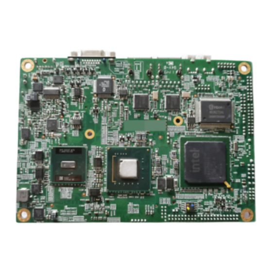
INTRODUCTION Introduction Product Description The IB887 is a small footprint single board computer that is configured with the Intel Atom processor N270 at 1.6GHz, FSB533 and the Mobile Intel 945GSE Express Chipset with the ICH7M. This 3.5-inch disk-size embedded board provides greater flexibility for developers of embedded computing solutions. -
Page 6: Checklist
INTRODUCTION Checklist Your IB887 package should include the items listed below. • The IB887 embedded board • This User’s Manual • 1 CD containing chipset drivers and flash memory utility • Cables are (shown below) optional. IB887 User’s Manual... -
Page 7: Ib887 Specifications
DF11 16-pin header x 1 for Audio SATA connector X1 4-pin SATA power connector 2-pin DC Power connector x1 Power Connector Digital I/O 4 in / 4 out Yes (256 segments, 0, 1, 2…255. sec/min) Watchdog Timer 102 x147mm Board Size IB887 User’s Manual... -
Page 8: Board Dimensions
INTRODUCTION Board Dimensions IB887 User’s Manual... -
Page 9: Installations
INSTALLATIONS Installations This section provides information on how to use the jumpers and connectors on the IB887 in order to set up a workable system. The topics covered are: Installing the Memory ................6 Setting the Jumpers ................7 Connectors on IB887 ................11... -
Page 10: Installing The Memory
INSTALLATIONS Installing the Memory The IB887 board supports one DDR2 memory socket that can support up to 1GB memory, DDR2 400/533 (w/o ECC function). Installing and Removing Memory Modules To install the DDR2 modules, locate the memory slot on the board and perform the following steps: 1. -
Page 11: Setting The Jumpers
INSTALLATIONS Setting the Jumpers Jumpers are used on IB887 to select various settings and features according to your needs and applications. Contact your supplier if you have doubts about the best configuration for your needs. The following lists the connectors on IB887 and their respective functions. - Page 12 INSTALLATIONS Jumper Locations on IB887 Jumpers on IB887 ................Page JP1: CompactFlash Slave/Master Selection ........... 9 JP2: LCD Panel Power Selection ............9 JP3: Clear CMOS Setting ..............9 JP4: ATX or AT Power Selection ............9 JP5, JP6, JP7: RS232/422/485 (COM2) Selection ......10...
- Page 13 INSTALLATIONS JP1: CompactFlash Slave/Master Selection CF Setting Master Slave JP2: LCD Panel Power Selection LCD Panel Power 3.3V JP3: Clear CMOS Setting Setting Normal Clear CMOS JP4: ATX or AT Power Selection ATX Power IB887 User’s Manual...
- Page 14 1-3 & 2-4 (pin closed) JP5: JP5: JP5: 3-5 & 4-6 1-3 & 2-4 1-3 & 2-4 COM2 is jumper selectable for RS-232, RS-422 and RS-485. Pin # Signal Name RS-232 R2-422 RS-485 DATA- DATA+ Ground Ground Ground IB887 User’s Manual...
-
Page 15: Connectors On Ib887
INSTALLATIONS Connectors on IB887 Connector Locations on IB887 ............12 CN3, CN4: USB0/1 Ports ..............13 CN1, CN2: GbE RJ45 Ports ..............13 CN6: PS/2 Keyboard/Mouse Connector ..........13 J18: DC-IN 12V Power Connector ............13 J1: Smart Battery Interface Connector ..........14 J2: IDE Connector ................ -
Page 16: Connector Locations On Ib887
INSTALLATIONS Connector Locations on IB887 Connector Locations on IB887 CN3, CN4: USB0/1 Ports ....................13 CN1, CN2: GbE RJ45 Ports ....................13 CN6: PS/2 Keyboard/Mouse Connector ................13 J18: DC-IN 12V Power Connector ..................13 J1: Smart Battery Interface Connector ................14 J2: IDE Connector ...................... -
Page 17: Cn3, Cn4: Usb0/1 Ports
CN3, CN4: USB0/1 Ports CN1, CN2: GbE RJ45 Ports CN6: PS/2 Keyboard/Mouse Connector Pin # Signal Name Keyboard data Mouse data Keyboard clock Mouse clock J18: DC-IN 12V Power Connector Pin # Signal Name DC in (12V only) Ground IB887 User’s Manual... -
Page 18: J1: Smart Battery Interface Connector
Ground Host IOR Ground IOCHRDY Host ALE DACK0 Ground IRQ14 No connect Address 1 No connect Address 0 Address 2 Chip select 0 Chip select 1 Activity Ground Ground N.C. J3: SPI Flash Connector (factory use only) IB887 User’s Manual... -
Page 19: J4: Usb2/Usb3 Connector (Df11 Type)
This LED will flash when the HDD is being accessed. Pin # Signal Name HDD Active Reset Switch: Pins 7 and 8 The reset switch allows the user to reset the system without turning the main power switch off and then on again. IB887 User’s Manual... -
Page 20: J8: Cf Socket
J11: LCD Backlight Connector (DC type) Pin # Signal Name +12V Backlight Enable *Backlight Adj (DC type) Ground * LCD backlight can be controlled by the OS. J12: HDD Power Connector Pin # Signal Name Ground Ground +12V IB887 User’s Manual... -
Page 21: J13: Com1, Com2 Serial Port (Df11 Type)
J14: LPC 80 Port Connector (debug use) J16: VGA Connector (D-sub, 15-pin) Signal Name Pin # Pin # Signal Name Green Blue N.C. N.C. DDCDATA HSYNC VSYNC DDCCLK J17: Digital I/O Signal Name Signal Name OUT3 OUT1 OUT2 OUT0 IB887 User’s Manual... -
Page 22: J19: Audio Connector (Df11 Type)
INSTALLATIONS J19: Audio Connector (DF11 type) Signal Name Pin # Pin # Signal Name LINEOUT R LINEOUT L Ground JD FRONT LINEIN R LINEIN Ground JD LINEIN MIC-In MIC L Ground JD MIC1 IB887 User’s Manual... -
Page 23: Bios Setup
PNP/PCI Configurations ..............38 PC Health Status .................. 39 Frequency/Voltage Control ..............40 Load Fail-Safe Defaults ............... 41 Load Optimized Defaults ..............41 Set Supervisor/User Password ............. 41 Save & Exit Setup ................41 Exit Without Saving ................41 IB887 User’s Manual... -
Page 24: Bios Introduction
<PgUp> and <PgDn> keys to change entries, <F1> for help and <Esc> to quit. When you enter the Setup utility, the Main Menu screen will appear on the screen. The Main Menu allows you to select from various setup functions and exit choices. IB887 User’s Manual... - Page 25 These defaults have been carefully chosen by both Award and your system manufacturer to provide the absolute maximum performance and reliability. Changing the defaults could cause the system to become unstable and crash in some cases. IB887 User’s Manual...
-
Page 26: Standard Cmos Setup
The following describes each item of this menu. Date The date format is: Day : Sun to Sat Month : 1 to 12 Date : 1 to 31 Year : 1999 to 2099 IB887 User’s Manual... - Page 27 The Access Mode selections are as follows: (HD < 528MB) (HD > 528MB and supports Logical Block Addressing) Large (for MS-DOS only) Auto Remarks: The main board supports two serial ATA ports and are represented in this setting as IDE Channel 0. IB887 User’s Manual...
- Page 28 The system boot will not be halted for a disk error; it will stop for all other errors. All, But Disk/Key The system boot will not be halted for a key- board or disk error; it will stop for all others. IB887 User’s Manual...
-
Page 29: Advanced Bios Features
When the CPU requests data, the system transfers the requested data from the main DRAM into cache memory, for even faster access by the CPU. These allow you to enable (speed up memory access) or disable the cache function. IB887 User’s Manual... - Page 30 Settings are from 6 to 30 characters per second. Typematic Delay (Msec) When the typematic rate is enabled, this item allows you to set the time interval for displaying the first and second characters. By default, this item is set to 250msec. IB887 User’s Manual...
- Page 31 OS/2 that depends on certain BIOS calls to access memory. The default setting is Non-OS/2. Small Logo (EPA) Show The EPA logo appears at the right side of the monitor screen when the system is boot up. IB887 User’s Manual...
-
Page 32: Advanced Chipset Features
SDRAM. DRAM RAS# Precharge This option sets the number of cycles required for the RAS to accumulate its charge before the SDRAM refreshes. The default setting for the Active to Precharge Delay is Auto. IB887 User’s Manual... - Page 33 1 Ch SPGW 18 bit 2 Ch SPGW 18 bit 1 Ch OpenLDI 18 bit 2 Ch OpenLDI 18 bit 1 Ch SPGW 24 bit 2 Ch SPGW 24 bit 1 Ch OpenLDI 24 bit 2 Ch OpenLDI 24 bit IB887 User’s Manual...
- Page 34 BIOS SETUP SDVO Panel Number This field allows you to select the SDVO Panel type. The default values for these ports are: 640x480 852x480 800x600 1024x768 1280x1024 1280x800 1366x768 1440x900 1600x1200 1920x1080 1920x1200 IB887 User’s Manual...
-
Page 35: Integrated Peripherals
PATA IDE Mode Secondary SATA port P0, P2 is Primary Phoenix - AwardBIOS CMOS Setup Utility Onboard Device Enabled ITEM HELP USB Controller Enabled Menu Level > USB 2.0 Controller Enabled USB Keyboard Support AC97 Audio Select Auto IB887 User’s Manual... - Page 36 When Auto is selected, the BIOS will select the best available mode. IDE Primary/Secondary Master/Slave UDMA These fields allow your system to improve disk I/O throughput to 33Mb/sec with the Ultra DMA/33 feature. The options are Auto and Disabled. IB887 User’s Manual...
- Page 37 ‘switch’ to power on the system. Onboard Serial Port These fields allow you to select the onboard serial ports and their addresses. The default values for these ports are: Serial Port 1 3F8/IRQ4 Serial Port 2 2F8/IRQ3 IB887 User’s Manual...
- Page 38 This field determines the UART 2 mode in your computer. The default value is Normal. PWRON After PWR-Fail This field sets the system power status whether on or off when power returns to the system from a power failure situation. IB887 User’s Manual...
-
Page 39: Power Management Setup
ACPI Function Enable this function to support ACPI (Advance Configuration and Power Interface). ACPI Suspend The default setting of the ACPI Suspend mode is S3(STR). RUN VGABIOS if S3 Resume The default setting of this field is Auto. IB887 User’s Manual... - Page 40 In the Delay 4 Sec mode, the system powers off when the power button is pressed for more than four seconds or enters the suspend mode when pressed for less than 4 seconds. IB887 User’s Manual...
- Page 41 When an I/O device wants to gain the attention of the operating system, it signals this by causing an IRQ to occur. When the operating system is ready to respond to the request, it interrupts itself and performs the service. IB887 User’s Manual...
-
Page 42: Pnp/Pci Configurations
MPEG ISA/VESA VGA card. When this field is disabled, a PCI/VGA cannot work with an MPEG ISA/VESA card. Maximum Payload Size The default setting of the PCI Express Maximum Payload Size is 128. IB887 User’s Manual... -
Page 43: Pc Health Status
Temperatures/Voltages These fields are the parameters of the hardware monitoring function feature of the board. The values are read-only values as monitored by the system and show the PC health status. IB887 User’s Manual... -
Page 44: Frequency/Voltage Control
Spread Spectrum Modulated This field sets the value of the spread spectrum. The default setting is Disabled. This field is for CE testing use only CPU Host / SRC PCI Clock This field is set to Default. IB887 User’s Manual... -
Page 45: Load Fail-Safe Defaults
Select this option to exit the Setup utility without saving the changes you have made in this session. Typing “Y” will quit the Setup utility without saving the modifications. Typing “N” will return you to Setup utility. IB887 User’s Manual... - Page 46 BIOS SETUP This page is intentionally left blank. IB887 User’s Manual...
-
Page 47: Drivers Installation
Realtek High Definition Audio Driver Installation ......46 LAN Drivers Installation ..............48 IMPORTANT NOTE: After installing your Windows operating system (Windows 2000/ XP), you must install first the Intel Chipset Software Installation Utility before proceeding with the drivers installation. IB887 User’s Manual... -
Page 48: Intel Chipset Software Installation Utility
4. Click Yes to accept the software license agreement and proceed with the installation process. 5. On Readme Information screen, click Next to continue the installation. 6. The Setup process is now complete. Click Finish to restart the computer and for changes to take effect. IB887 User’s Manual... -
Page 49: Vga Drivers Installation
4. Click Yes to to agree with the license agreement and continue the installation. 5. Click Next in the Readme File Information window. 6. Click Next in the Setup Progress window. 7. Setup is now complete. Click Finish to restart the computer and for changes to take effect. IB887 User’s Manual... -
Page 50: Realtek High Definition Audio Driver Installation
Intel(R) I945GM/GME/GSE Chipset Drivers, and then Realtek Audio Driver. 2. Click Realtek High Definition Codec Audio Driver. 3. When the welcome screen to the InstallShield Wizard for Realtek High Definition Codec Audio Driver appears, click Next to start the installation. IB887 User’s Manual... - Page 51 DRIVERS INSTALLATION 4. When the InstallShieldWizard has finished performing maintenance operations on Realtek High Definition Audio Driver, click Finish to restart the computer. IB887 User’s Manual...
-
Page 52: Lan Drivers Installation
2. In the Intel® Network Connections screen*, click Install Drivers and Software. *Under Windows 2000, driver installation will require the Windows Management Instrumentation Service running in order to proceed. Refer to this information at the end of this section. IB887 User’s Manual... - Page 53 4. In the Setup Options, click the checkbox as shown below and click Next. 4. In the InstallShield Wizard screen, click Install to begin the installation. 5. InstallShield Wizard is completed. Click Finish to exit the Wizard. IB887 User’s Manual...
- Page 54 Windows 2000, the message below asking to start the Windows Management Instrument Service will appear. At this moment, click OK, and proceed to run the service requested. On the Windows desktop, right click the My Computer icon and click Manage. IB887 User’s Manual...
- Page 55 Double click two Services names including Windows Management Instrumentation and Windows Management Instrumentation Driver Extensions in order to configure their Startup type as Automatic as shown below. After this step, you can go back to install the LAN driver. IB887 User’s Manual...
-
Page 56: Appendix
Parallel Port #1(LPT1) 360 - 36F Network Ports 3B0 - 3BF Monochrome & Printer adapter 3C0 - 3CF EGA adapter 3D0 - 3DF CGA adapter 3F0h - 3F7h Floppy Disk Controller 3F8h - 3FFh Serial Port #1(COM1) IB887 User’s Manual... -
Page 57: Interrupt Request Lines (Irq)
Serial Port #2 IRQ4 Serial Port #1 IRQ5 Reserved IRQ6 Floppy Disk Controller IRQ7 Parallel Port #1 IRQ8 Real Time Clock IRQ9 Reserved IRQ10 Reserved IRQ11 Reserved IRQ12 PS/2 Mouse IRQ13 80287 IRQ14 Primary IDE IRQ15 Secondary IDE IB887 User’s Manual... -
Page 58: Watchdog Timer Configuration
(argc != 2) printf(" Parameter incorrect!!\n"); return 1; if (Init_W627EHF() == 0) printf(" Winbond 83627HF is not detected, program abort.\n"); return 1; bTime = strtol (argv[1], endptr, 10); printf("System will reset after %d seconds\n", bTime); EnableWDT(bTime); return 0; //=========================================================================== IB887 User’s Manual... - Page 59 = Get_W627EHF_Reg( 0xF5); bBuf &= (!0x08); Set_W627EHF_Reg( 0xF5, bBuf); //count mode is second Set_W627EHF_Reg( 0xF6, interval); //set timer //=========================================================================== void DisableWDT(void) Set_W627EHF_LD(0x08); //switch to logic device 8 Set_W627EHF_Reg(0xF6, 0x00); //clear watchdog timer Set_W627EHF_Reg(0x30, 0x00); //watchdog disabled //=========================================================================== IB887 User’s Manual...
- Page 60 Init_Finish; W627EHF_BASE = 0x00; result = W627EHF_BASE; Init_Finish: return (result); //=========================================================================== void Unlock_W627EHF (void) outportb(W627EHF_INDEX_PORT, W627EHF_UNLOCK); outportb(W627EHF_INDEX_PORT, W627EHF_UNLOCK); //=========================================================================== void Lock_W627EHF (void) outportb(W627EHF_INDEX_PORT, W627EHF_LOCK); //=========================================================================== void Set_W627EHF_LD( unsigned char LD) Unlock_W627EHF(); outportb(W627EHF_INDEX_PORT, W627EHF_REG_LD); outportb(W627EHF_DATA_PORT, LD); Lock_W627EHF(); IB887 User’s Manual...
- Page 61 (W627EHF_BASE) #define W627EHF_DATA_PORT (W627EHF_BASE+1) //=========================================================================== #define W627EHF_REG_LD 0x07 //=========================================================================== #define W627EHF_UNLOCK 0x87 #define W627EHF_LOCK 0xAA //=========================================================================== unsigned int Init_W627EHF(void); void Set_W627EHF_LD( unsigned char); void Set_W627EHF_Reg( unsigned char, unsigned char); unsigned char Get_W627EHF_Reg( unsigned char); //=========================================================================== #endif //__W627EHF_H IB887 User’s Manual...
- Page 62 APPENDIX This page is intentionally left blank. IB887 User’s Manual...
Need help?
Do you have a question about the IB887 and is the answer not in the manual?
Questions and answers