Table of Contents
Advertisement
Advertisement
Chapters
Table of Contents
Troubleshooting

Related Manuals for Rowe GrandSTAR


Summary of Contents for Rowe GrandSTAR
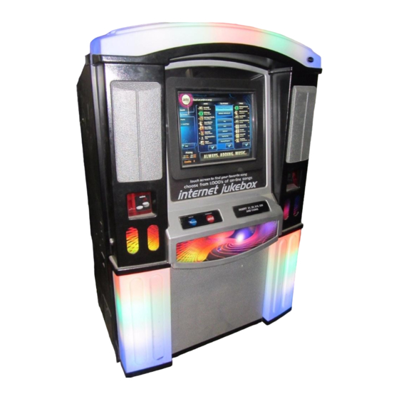
- Page 1 ® GrandSTAR Internet Jukebox 22022603 Volume 1 of 1 Rev. G...
- Page 3 GrandSTAR Internet Jukebox Safety Safety IMPORTANT SAFETY INFORMATION 1. Read these instructions. 10. Protect the power cord from being walked on or pinched, particularly at plugs, convenience receptacles, and the point where they exit from the jukebox. 2. Keep these instructions.
- Page 4 Safety GrandSTAR Internet Jukebox CAUTION! The lightning flash with arrowhead symbol, within an equilateral triangle is intended to alert the user to the presence of non- insulated “dangerous voltage” within the product’s enclosure that may be of sufficient magnitude to constitute a risk of electric shock to persons.
-
Page 5: Table Of Contents
Service Features: .........................1-2 Unpacking Instructions ......................1-3 Doors ............................1-3 Visual Inspection ........................1-3 Handy Case ..........................1-3 Warranty Registration Card ......................1-3 Major Components of the GrandSTAR ..................1-4 Core Computer ........................1-4 Touch-screen 19” LCD Monitor ....................1-4 System Power Supply ......................1-4 Transformer Assembly ......................1-4 Rowelink Controller ......................1-4 LED Controller ........................1-4... - Page 6 Contents GrandSTAR Internet Jukebox SECTION: 3 SOUND SYSTEM SETUP ..................3-1 Introduction ..........................3-1 Extension Speaker Operation ....................3-1 70-Volt Speakers ........................3-1 Low Impedance Speakers ....................3-2 Selecting Speaker Power ......................3-3 General Instructions ......................3-3 Selection Procedures ......................3-3 Extension Speakers Connected E1 to E7 ................
- Page 7 GrandSTAR Internet Jukebox Contents Introduction ..........................7-1 Power Supply Board .........................7-2 +9 V LED ..........................7-2 +12 V LED ..........................7-2 +24 V LED ..........................7-2 Rowelink Controller ........................7-2 5 VDC, 12 VDC, 24 VDC LEDs ....................7-2 IR RCV LED .........................7-2 KID RL TX LED ........................7-2 Core Computer RL RX LED ....................7-2...
- Page 8 Contents GrandSTAR Internet Jukebox Component Identification and Location (Internal View, Right Hand Side) ......8-20 Shell Assembly (Front View with Lower Door Removed) ............8-22 Bill Acceptor Assembly ......................8-24 Core Computer Assembly - Exploded View ................8-26 LED Controller Assembly ......................8-28 Transformer Assembly ......................
- Page 9 GrandSTAR Internet Jukebox Tables List of Tables Table 3-1 - Extension Speaker Worksheet Sheet 1 ..................3-3 Table 3-2 - Extension Speaker Worksheet Sheet 2 ..................3-4 Table 3-3 - Extension Speaker Worksheet Sheet 3 ..................3-5 Table 3-4 - Extension Speaker Worksheet Sheet 4 ..................3-6 Table 3-5 - Jukebox Speaker Power ......................
- Page 10 Tables GrandSTAR Internet Jukebox This page intentionally left blank viii 22022603...
- Page 11 Figure 6-1 – Calibrate Button ........................... 6-2 Figure 6-2 – Calibration Screen ........................6-2 Figure 6-3 – Filter Removal..........................6-3 Figure 7-1 – GrandSTAR Wiring Diagram (Sheet 1) ..................7-5 Figure 8-1 – Front View ............................ 8-4 Figure 8-2 – Rear View ............................ 8-6 Figure 8-3 –...
- Page 12 Figures GrandSTAR Internet Jukebox Figure 8-11 – Shell Assembly (Front View with Lower Door Removed) ............8-22 Figure 8-12 – Bill Acceptor Assembly ......................8-24 Figure 8-13 – Core Computer Assembly - Exploded View ................8-26 Figure 8-14 – LED Controller Assembly ......................8-28 Figure 8-15 –...
-
Page 13: Section: 1 Unpacking & System Description
- the AMI Entertainment ® network. This network is a digital platform that delivers music across the Internet to Rowe Jukeboxes anywhere. The GrandSTAR jukebox is an Internet-enabled jukebox that allows all the traditional functions of a jukebox backed by the power of the Internet. -
Page 14: Grandstar Jukebox Features
Unpacking & System Description GrandSTAR Internet Jukebox GrandSTAR Jukebox Features The major GrandSTAR features are: General Features: • Sturdy construction and reliable design • Conveniently located customer, operator, and service controls • All major components are modular and easy to replace, if needed •... -
Page 15: Unpacking Instructions
Damage claims are your responsibility. Do not return damaged merchandise until after your claim has been established. Once your claim has been established, merchandise may be returned to your Rowe distributor for repair. The invoice amount for repair charges can then be collected from the carrier. -
Page 16: Major Components Of The Grandstar
The system power supply produces +9 VDC, +12 VDC, +24 VDC, and contains a relay to switch the jukebox lights, touch-screen monitor, and the Bill Acceptor ON or OFF. It has an IEC 320 power inlet, two 6A circuit breakers, a 3A breaker (unused in GrandSTAR) and two 4A fuses. -
Page 17: Volume Control Unit
If an existing 100 foot cable is already in place, you can use the 3-wire or 4-wire (see Figure 3-6) alternate wiring. • The POWER button turns the GrandSTAR Jukebox lights, touch-screen monitor and Bill Acceptor ON or OFF. •... -
Page 18: Figure 1-1 - Major Components
Unpacking & System Description GrandSTAR Internet Jukebox TOUCH-SCREEN & 19” LCD MONITOR LCD POWER MID-FREQUENCY ADAPTER SPEAKER HIGH-FREQUENCY SPEAKER ROUTER ROUTER RESET SWITCH SYSTEM POWER 1000 WATT DIGITAL SUPPLY AMPLIFIER SURGE SUPPRESSOR & CONTROLLER ON/OFF SWITCH COIN INLET ATX RESET SWITCH... -
Page 19: Grandstar Specifications
GrandSTAR Internet Jukebox Unpacking & System Description GrandSTAR Specifications General Depth ......................... 25-1/2 in. Width ......................... 41-1/2 in. Height ........................ 63-1/2 in. Power Requirements ................120 VAC 60 Hz. 1200 watts 11.9 amps Pricing ....................See “Credit Pricing” in The “Network Setup and Jukebox Operation Manual” (P/N21822693) Bill Acceptor ...... - Page 20 Unpacking & System Description GrandSTAR Internet Jukebox This page intentionally left blank 22022603...
-
Page 21: Section: 2 Installing Hard Drive & Testing
GrandSTAR Internet Jukebox Installing Hard Drive & Testing Section: 2 Installing Hard Drive & Testing Installing the Hard Drive The system will not operate without a Hard Drive installed. These are sold separately and are available with several preloaded music genres - Country, Hard Rock, R&B/Soul, etc. -
Page 22: Figure 2-2 - Hard Drive Installed In Housing
Installing Hard Drive & Testing GrandSTAR Internet Jukebox 4. Place the hard drive in the housing (Note the hard drive connector's relationship to the hooks) and secure it by tightening the four spring-loaded screws as shown in Figure 2-2. POSITION DRIVE AS... -
Page 23: Figure 2-3 - Ide & Power Cable
GrandSTAR Internet Jukebox Installing Hard Drive & Testing 5. Carefully extend the IDE cable from inside the Core Computer and connect it to the hard drive. Locate a 4-pin power connector from the ATX Power Supply and connect it to the hard drive also. Refer to Figure 2-3. -
Page 24: Figure 2-4 - Hard Drive Installed
Installing Hard Drive & Testing GrandSTAR Internet Jukebox 6. Rotate the housing into position and hook it into the slots on the Core Computer cover. Slide the Hard Drive Clamp over the spring-loaded screw and secure the clamp in place by tightening the Thumbscrew. Carefully dress the Hard Drives IDE and Power Cable. -
Page 25: Testing The Unit
GrandSTAR Internet Jukebox Installing Hard Drive & Testing Testing the Unit Once the jukebox is powered on and the user interface is running (see Figure - Jukebox User Interface), try the following procedures before moving and installing the unit at the venue:... -
Page 26: Credit Test
Installing Hard Drive & Testing GrandSTAR Internet Jukebox Credit Test Insert a dollar bill into the Bill Acceptor and ensure that the increment in credits corresponds with the pricing scheme for the jukebox. See Bill Acceptor settings on page 5-5 for the factory settings of the Bill Acceptor. -
Page 27: Music Selection And Pricing
Setup, Jukebox Operation, Operator Setup Screens” for setup information. Connection Rules The first time you boot up the GrandSTAR with your hard drive, a 60-day licensing grace period will begin. If at the end of these 60 days your jukebox has not connected to the AMI Entertainment Network to validate its’... -
Page 28: Wireless Router Reception
GrandSTAR Internet Jukebox Wireless Router Reception The GrandSTAR jukebox is equipped with a Wireless Router to allow you to use the Merit™ game connection for song selection. The jukebox is shipped to you with the Wireless Router Antenna in the horizontal position. In some interference prone locations, the Antenna is more effective in the vertical position. -
Page 29: Figure 2-9 - Wireless Router Antenna In Vertical Position
GrandSTAR Internet Jukebox Installing Hard Drive & Testing To change the Antenna position: 1. Remove the plastic hole plug from the top of the Cabinet. 2. Loosen the four Router Mounting Bracket Screws, and slide the Bracket off the Screws. - Page 30 Installing Hard Drive & Testing GrandSTAR Internet Jukebox This page intentionally left blank 2-10 22022603...
-
Page 31: Section: 3 Sound System Setup
GrandSTAR Internet Jukebox Sound System Setup Section: 3 Sound System Setup Introduction See the included manual “Network Setup, Jukebox Operation, Operator Setup Screens” if you have any questions about setting up the Network or the jukebox for operation. Extension Speaker Operation To avoid a poor sound quality, care must be taken when adding extension speakers. -
Page 32: Low Impedance Speakers
Sound System Setup GrandSTAR Internet Jukebox Low Impedance Speakers Low impedance speakers (8 or 4 ohm) can be used when the connecting cable is less than 100 feet. 4-OHM SPEAKERS (PARALLEL CONNECTIONS) No more than one 4-ohm speaker should be connected to a speaker line. If several 4-ohm speakers are to be used, each speaker should have its’... -
Page 33: Selecting Speaker Power
GrandSTAR Internet Jukebox Sound System Setup Selecting Speaker Power General Instructions This section will lead you through the power and speaker selection process. This process consists of three major steps and several smaller steps. The major steps are: 1. Identifying the extension speakers and computing the speaker power for speakers connected E1 to E7, 70V speakers connected A1 to A2, and tapped speakers connected to E1 through E6. -
Page 34: 4-Ohm Speakers Connected To Transformer Taps E1 Through E6
Sound System Setup GrandSTAR Internet Jukebox Table 3-2 Extension Speaker Worksheet Sheet 2 4-Ohm Speakers Connected To Transformer Taps E1 through E6 Place the quantity of speakers in the blank under and multiply the quantity times the power consumption. Place your results in the blank under TOTAL 4-Ohm Speakers connected to Channel 1 transformer taps. -
Page 35: 8-Ohm Speakers Connected To Transformer Taps E1 Through E6
GrandSTAR Internet Jukebox Sound System Setup Table 3-3 Extension Speaker Worksheet Sheet 3 8-OHM Speakers Connected To Transformer Taps E1 through E6 Place the quantity of speakers in the blank under and multiply the quantity times the power consumption. Place your results in the blank under... -
Page 36: Combine Power Consumption Of All Speakers
Sound System Setup GrandSTAR Internet Jukebox Table 3-4 Extension Speaker Worksheet Sheet 4 Combine power consumption of all speakers: Channel 1 Channel 2 Connected E1 to E7 Sum of tapped, and 70 Volt A1, A2 must Tapped 4-ohm not exceed 125 watts Tapped 8-ohm per channel. -
Page 37: Amplifier Overload Check
GrandSTAR Internet Jukebox Sound System Setup Amplifier Overload Check Check that the amplifier is not overloaded by performing the following four steps: 1. Make sure that the extension speakers are connected to the audio output transformer proper terminals (E1 through E7, and A1, A2). -
Page 38: Figure 3-1 - Speaker Connections
Sound System Setup GrandSTAR Internet Jukebox Figure 3-1 - Speaker Connections 22022603... - Page 39 GrandSTAR Internet Jukebox Sound System Setup 22022603...
-
Page 40: Figure 3-2 - Audio Output Transformer Wiring Diagram (#40832115)
Sound System Setup GrandSTAR Internet Jukebox Figure 3-2 - Audio Output Transformer Wiring Diagram (#40832115) 3-10 22022603... -
Page 41: Speaker Synopsis
GrandSTAR Internet Jukebox Sound System Setup Speaker Synopsis 1000 Watts of RMS Power per Amplifier or 500 Watts per Channel. The generic speaker wiring diagrams cover 4 to 32 speakers. These speakers are expensive, providing a lot of sound in a localized area, which does not always optimize the room sound. -
Page 42: Figure 3-3 Diagrams 1 - 5 - External Speaker Connections With Jukebox Speakers Connected
Sound System Setup GrandSTAR Internet Jukebox Figure 3-3 Diagrams 1 - 5 - External Speaker Connections with Jukebox Speakers Connected 3-12 22022603... - Page 43 GrandSTAR Internet Jukebox Sound System Setup Figure 3-3 Diagram 2 - Ten Speakers with Jukebox Speakers Connected 22022603 3-13...
- Page 44 Sound System Setup GrandSTAR Internet Jukebox Figure 3-3 Diagram 3 - Sixteen Speakers with Jukebox Speakers Connected 3-14 22022603...
- Page 45 GrandSTAR Internet Jukebox Sound System Setup Figure 3-3 Diagram 4 - Twenty Eight Speakers with Jukebox Speakers Connected 22022603 3-15...
- Page 46 Sound System Setup GrandSTAR Internet Jukebox Figure 3-3 Diagram 5 - Low Voltage and 70 Volt Speakers with Jukebox Speakers Connected 3-16 22022603...
-
Page 47: Figure 3-4 Diagrams 1N - 3N - External Speaker Connections With Jukebox Speakers Not Connected
GrandSTAR Internet Jukebox Sound System Setup Figure 3-4 Diagrams 1N - 3N – External Speaker Connections with Jukebox Speakers NOT Connected 22022603 3-17... - Page 48 Sound System Setup GrandSTAR Internet Jukebox Figure 3-4 Diagram 2N - 8 Speakers with Jukebox Speakers NOT Connected 3-18 22022603...
- Page 49 GrandSTAR Internet Jukebox Sound System Setup Figure 3-4 Diagram 3N - 16 Speakers with Jukebox Speakers NOT Connected 22022603 3-19...
-
Page 50: Figure 3-5 - Volume Control Unit
Sound System Setup GrandSTAR Internet Jukebox Figure 3-5 - Volume Control Unit 3-20 22022603... -
Page 51: Figure 3-6 - Volume Connections Using Existing 3-Wire Or 4-Wire Cable
GrandSTAR Internet Jukebox Sound System Setup Figure 3-6 – Volume Connections Using Existing 3-Wire or 4-Wire Cable 22022603 3-21... - Page 52 Sound System Setup GrandSTAR Internet Jukebox This page intentionally left blank 3-22 22022603...
-
Page 53: Section: 4 Adding Microphones
Up to two microphones can be plugged into the 4 Channel Preamplifier and used for paging. Microphones’ can be Rowe custom design, CB or “Rowe CB”, low level balanced, low level unbalanced, or Rowe wireless. NOTE 1: A 26679501 Paging System is needed to use low-level balanced and unbalanced microphones. -
Page 54: Figure 4-2 - Paging Microphone Setup Screen
Step 2. To test the microphone the jukebox should be at the location with all extension speakers installed. Set the volume control on the Rowe custom microphone, or the Paging MIC Adapter, to maximum and do test pages with no music playing and with a song playing. If necessary change the levels by setting the "Microphone Volume During Paging", the "Audio Volume During Paging", and the... -
Page 55: Figure 4-3 - Vcu Setup Screen
GrandSTAR Internet Jukebox Adding Microphones • Touch Main Menu to save your changes and return to Hardware Setup screen. Repeat Step 2 and check the results. Step 4. If not in SERVICE mode Push the SERVICE button on the Rowelink Controller to enter the Main Menu, then Touch HARDWARE SETUP. - Page 56 Adding Microphones GrandSTAR Internet Jukebox This page intentionally left blank 22022603...
-
Page 57: Section: 5 Led Lighting And Bill Acceptor
Introduction LED Control Assembly (#40931103) The LED Control Assembly in the GrandSTAR jukebox supplies all the lighting in the jukebox. There are no fluorescent bulbs, starters, ballasts, or 12 V peanut lights. All lighting is supplied by the use of 29 ultra bright LEDs. -
Page 58: Flash Rate (Speed) Of The Leds
LED Lighting and Bill Acceptor GrandSTAR Internet Jukebox Flash Rate (Speed) of the LEDs The flash rate (speed) can be adjusted from very rapid to approximately every two seconds. To adjust the flash rate with the IR Remote, push SPEED, then push LIGHTS+ to make the flash rate faster, or push LIGHTS- to make the flash rate slower. -
Page 59: Setting Led Mode
GrandSTAR Internet Jukebox LED Lighting and Bill Acceptor Setting LED Mode Two LED flash modes are available and can be adjusted as follows using the program DIP switches. Program DIP Sw#6 controls the Mode Mode 1 is Sw#6 OFF “Juke” Standby = LEDs Flash “Juke”... -
Page 60: Adjusting Patter With The Ir Remote
LED Lighting and Bill Acceptor GrandSTAR Internet Jukebox Adjusting Pattern with the lR Remote: Push PATTERN, then push either LIGHTS+ or LIGHTS- (Cycles through Patterns 1, 2, and 3). Figure 5-2 – LED Control Assembly Figure 5-3 – Program DIP Switches... -
Page 61: Bill Acceptor Settings
LED Lighting and Bill Acceptor Bill Acceptor Settings The GrandStar uses either a Coinco® Vantage™ or a MEI® AE2611 Bill Acceptor. In order to function properly in the GrandStar, these Bill Acceptors must be configured as follows: Coinco Vantage Setup Figure 5-4 shows the location and orientation of the DIP Switches. -
Page 62: Figure 5-6 Removing The Lower Housing
Figure 5-7 shows the 5 LEDs and their meanings. Figure 5-7 Configuration Settings The ‘ON’ and ‘OFF’ settings shown are the Rowe default settings 5. Press the Service Mode Button and release to step through the Bill Acceptance options. When you have the bills enabled as desired, press the Service Mode Button and hold it until the Page LED begins to blink in a 2-flash pattern. -
Page 63: Mei Ae2611 Setup
GrandSTAR Internet Jukebox LED Lighting and Bill Acceptor 7. Continue these steps through the Page 3 and Page 4 options. When you have the settings as you want them, simply re-install the Lower Housing. The Inlet LEDs will flash 5 times confirming that your settings have been saved. - Page 64 LED Lighting and Bill Acceptor GrandSTAR Internet Jukebox This page intentionally left blank 22022603...
-
Page 65: Section: 6 Routine Service
GrandSTAR Internet Jukebox Routine Service Section: 6 Routine Service Introduction Routine and preventative maintenance is to be performed on your regularly scheduled periodic service call. This section discusses how to do preventive maintenance procedures. Changing music, collecting statistic figures, and changing other location-specific features can be done using the AMI Entertainment Secure Website via the Internet. -
Page 66: Preventive Maintenance
Touch-screen Calibration The following procedure describes how to calibrate the touch-screen: 1. Power on the GrandSTAR jukebox and allow it to complete the startup sequence. 2. Open the door of the jukebox. 3. Locate the “Calibrate” button on the Rowelink Controller. Refer to Figure 6-1. -
Page 67: Air Filter
Routine Service Air Filter Filtered cooling air is provided for the components inside the GrandSTAR via a fan mounted on the back of the jukebox. The speed of this fan is controlled by the Rowelink Controller – if the temperature is moderate, the fan runs at a low speed, but as the temperature inside the box rises, the fan is driven faster. - Page 68 Routine Service GrandSTAR Internet Jukebox This page intentionally left blank 22022603...
-
Page 69: Section: 7 Troubleshooting
Section: 7 Troubleshooting Introduction The GrandSTAR Jukebox incorporates several modules which plug in for rapid service. The most likely cause of jukebox problems is: 1. Continuous or intermittent open circuits in a harness. The cause can be broken or cut wires, a damaged terminal, or a bad terminal crimp. -
Page 70: Power Supply Board
Troubleshooting GrandSTAR Internet Jukebox Power Supply Board +9 V LED Should be on. Indicates +9 VDC is available at the Power Supply. +12 V LED Should be on. Indicates +12 VDC is available at the Power Supply. +24 V LED Should be on. -
Page 71: Channel Preamplifier
GrandSTAR Internet Jukebox Troubleshooting 4 Channel Preamplifier Power LED Should be on. Indicates when all 4 voltages are present (+5 V, +8.5 V, +15 V, -15 V). Status LED On Power Up (Power applied to the AV Controller) this LED flashes 3 times. -
Page 72: Sequence Of Operation
• Low-level hardware checks • Windows XP Embedded Operating System Loads • GrandSTAR Operating System Loads Step 3: The user interface (see Figure ) is viewed on the monitor. No music is in the queue, no selections are available and the amplifier is muted. -
Page 73: Figure 7-1 - Grandstar Wiring Diagram (Sheet 1)
TO 34039924 HARNESS SHEET 4 TO ROWELINK CONTROLLER P14 SHEET 2 34032614 TO LED CONTROLLER POWER SHEET 5 TO ROWELINK CONTROLLER P2 SHEET 2 FOR EQUIVALENT ENGINEERING DRAWING, SEE 21871076-Q7 REV B Figure 7-1 – GrandSTAR Wiring Diagram (Sheet 1) 22022603... - Page 74 SHEET 3 TO POWER SUPPLY ASSEMBLY P3 SHEET 1 TO PIN 15 COMPONENTS POWER TO POWER SUPPLY CONNECTOR SHEET 1 ASSEMBLY P2 SHEET 1 FOR EQUIVALENT ENGINEERING DRAWING, SEE 21871076-Q7 REV B Figure 7-1 – GrandSTAR Wiring Diagram (Sheet 2) 22022603...
- Page 75 Extremely Cool 34033402 1000(500x2) Watt RMS TO 34059105 70 V **B/W Audio HARNESS * R/Y **BR Digital Amplifier SHEET 1 34059105 **B/W **BR FOR EQUIVALENT ENGINEERING DRAWING, SEE 21871076-Q7 REV B Figure 7-1 – GrandSTAR Wiring Diagram (Sheet 3) 22022603...
- Page 76 R H ARNES 40830901 T T RANSFORME R A DAPTOR 34054604 HORN HARNES S S HEET DOOR SPEAKER HARNES HORN 40830901 RIGHT 40830806 FOR EQUIVALENT ENGINEERING DRAWING, SEE 21871076-Q7 REV B Figure 7-1 – GrandSTAR Wiring Diagram (Sheet 3A) 22022603...
- Page 77 TO 34039924 HARNESS SHEET 1 30934217 Green-Audio POWER TO 4 CH PREAMPLIFIER TO 34037927 SUPPLY 30934222 MAIN STEREO INPUT HARNESS SHEET 3 SHEET 1 FOR EQUIVALENT ENGINEERING DRAWING, SEE 21871076-Q7 REV B Figure 7-1 – GrandSTAR Wiring Diagram (Sheet 4) 22022603...
-
Page 78: Figure 5-2 - Led Control Assembly
SENSOR TO 4 CH PREAMPLIFIER AUX OUT CH1 - CH2 SHEET 3 34039924 120 VAC TO 34039924 HARNESS SHEET 1 FOR EQUIVALENT ENGINEERING DRAWING, SEE 21871076-Q7 REV B Figure 7-1 – GrandSTAR Wiring Diagram - Lighting (Sheet 5) 7-10 22022603... - Page 79 BLUE - 4 70035344 YELLOW - 8 70035347 GREEN - 4 70035345 WHITE - 15 70035340 WHITE - 19 70035340 FOR EQUIVALENT ENGINEERING DRAWING, SEE 21871076-Q7 REV B Figure 7-1 – GrandSTAR Wiring Diagram - LED Lighting (Sheet 5A) 22022603 7-11...
-
Page 80: Troubleshooting Charts
Troubleshooting GrandSTAR Internet Jukebox Troubleshooting Charts The best way to determine a problem is to isolate its’ cause. The following charts should help to narrow down which module is failing and whether it can be fixed or needs to be replaced. - Page 81 GrandSTAR Internet Jukebox Troubleshooting Trouble Symptom Probable Cause Jukebox will not operate when When plugged into a standard 1. The Power button was Powered ON. wall outlet, the LEDs fail to light. pressed on Volume Control Unit or IR Remote.
- Page 82 Troubleshooting GrandSTAR Internet Jukebox Trouble Symptom Probable Cause The bill acceptor does not work. The bill acceptor will not accept 1. The cash box is full. a bill. 2. The cash box was not correctly re-installed on the bill acceptor.
- Page 83 GrandSTAR Internet Jukebox Troubleshooting Trouble Symptom Probable Cause Router does not work. When the power supply is 1. The AC adapter is not connected to the router, nothing fully inserted in the AC happens. outlet in the power supply, or the DC adapter...
- Page 84 Troubleshooting GrandSTAR Internet Jukebox Trouble Symptom Probable Cause The “Music on Demand” feature The feature has never been 1. There is no Ethernet does not work. available in the location. cable connection between the router and the Core Computer. 2. The Ethernet cable is not...
-
Page 85: Section: 8 Parts Catalog
GrandSTAR Internet Jukebox Parts Catalog Section: 8 Parts Catalog Introduction ..................8-1 Catalog Description ..................8-3 Parts List Description ................8-3 Ordering Replacement Parts ..............8-3 Figure 8-1 – Front View........................8-4 Figure 8-2 – Rear View ........................8-6 Figure 8-3 – Top Door Assembly (External View) ............... 8-8 Figure 8-4 –... - Page 86 Parts Catalog GrandSTAR Internet Jukebox This page intentionally left blank 22022603...
-
Page 87: Introduction
Reference numbers are not used when items are listed for reference purposes only or when the item listed is an alternate part. • Rowe Part Number — This column lists the part number to use when ordering replacement parts or making inquiries. -
Page 88: Figure 8-1 - Front View
Parts Catalog GrandSTAR Internet Jukebox Figure 8-1 – Front View 22022603... -
Page 89: Jukebox Assembly (Front View)
Door Assembly – Top (Red) See Figure 8-3, Figure 8-4, Figure 8-5 ..Ref. 61184501 Lower Door Assembly (Gold) See Figure 8-6, Figure 8-7 (Used on Red GrandSTAR) ......Ref. 61184502 Lower Door Assembly (Silver) See Figure 8-6, Figure 8-7 (Used on Black GrandSTAR) ......Ref. -
Page 90: Figure 8-2 - Rear View
Parts Catalog GrandSTAR Internet Jukebox Figure 8-2 – Rear View 22022603... -
Page 91: Jukebox Assembly (Rear View)
Parts Catalog Jukebox Assembly (Rear View) Refer to Figure 8-2. Ref. Part No. Description 61184401 Jukebox Assembly (Black GrandSTAR) ............ Ref. 61184402 Jukebox Assembly (Red GrandSTAR)............Ref. 34089801 Bracket - Light Block ..................3 40942702 Frame - Filter ....................1 34053001 Pad - Filter (Not Shown) ................ -
Page 92: Figure 8-3 - Top Door Assembly (External View)
Parts Catalog GrandSTAR Internet Jukebox Figure 8-3 – Top Door Assembly (External View) 22022603... -
Page 93: Top Door Assembly (External View)
Panel-Graphics (Right) ................... 1 61183501 Top Door - Black/Silver ................... 1 61183502 Top Door - Red/Gold ..................1 61140203 Grill, Speaker-Top Door - Silver (Black GrandSTAR) ........2 61140201 Grill, Speaker-Top Door - Gold (Red GrandSTAR) ........2 34043502 Medallion ......................1 70135517 Palnut ...................... -
Page 94: Figure 8-4 - Top Door Assembly (Internal View)
Parts Catalog GrandSTAR Internet Jukebox Figure 8-4 – Top Door Assembly (Internal View) 8-10 22022603... -
Page 95: Top Door Assembly (Internal View)
Top Door Assembly (Internal View) Refer to Figure 8-4. Ref. Part No. Description 61183401 Door Assembly – Top (Black GrandSTAR) ..........Ref. 61183402 Door Assembly – Top (Red GrandSTAR) ..........Ref. 70093403 Cable Clamp - 1” ..................... 4 61167003 Touch Screen & Panel (See Figure 8-20) ............1 •... -
Page 96: Figure 8-5 - Top Door Assembly (Internal - Top And Side View)
Parts Catalog GrandSTAR Internet Jukebox Figure 8-5 – Top Door Assembly (Internal - Top and Side View) 8-12 22022603... -
Page 97: Top Door Assembly (Internal - Top And Side View)
Door Assembly – Top (Red GrandSTAR) ..........Ref. 22162801 Bracket - Crown LED (Side) ................2 34045102 Circuit Board Assembly - Crown, Pilaster LED BL, W (Black GrandSTAR) ..2 34045106 Circuit Board Assembly - Crown, Pilaster LED Y, R (Red GrandSTAR) ..2 34045103 Circuit Board Assembly - Crown, Pilaster LED R, G (Black GrandSTAR) .. -
Page 98: Lower Door Assembly (External View)
Parts Catalog GrandSTAR Internet Jukebox Figure 8-6 – Lower Door Assembly (External View) Lower Door Assembly (External View) Refer to Figure 8-6. Ref. Part No. Description 61184501 Lower Door Assembly - Gold (Red GS-1) ..........Ref. 61184502 Lower Door Assembly - Silver (Black GS-1) ..........Ref. -
Page 99: Lower Door Assembly (Internal View)
GrandSTAR Internet Jukebox Parts Catalog Figure 8-7 – Lower Door Assembly (Internal View) Lower Door Assembly (Internal View) Refer to Figure 8-7. Ref. Part No. Description 61184501 Lower Door Assembly - Gold (Red GS-1) ..........Ref. 61184502 Lower Door Assembly - Silver (Black GS-1) ..........Ref. -
Page 100: Figure 8-8 - Component Identification And Location (Internal View, Left Hand Side)
Parts Catalog GrandSTAR Internet Jukebox 7, 7A Figure 8-8 – Component Identification and Location (Internal View, Left Hand Side) 8-16 22022603... -
Page 101: Component Identification And Location (Internal View, Left Hand Side)
GrandSTAR Internet Jukebox Parts Catalog Component Identification and Location (Internal View, Left Hand Side) Refer to Figure 8-8. Part No. Description 40955703 Rowelink Controller Assembly (See Figure 8-19) .......... 1 34034602 Plate - Cover, Amplifier ................... 1 21759301 Cover - Cord Hole ................... 1 22145809 Power Supply System with Router Power (See Figure 8-16) ...... -
Page 102: Figure 8-9 - Pilaster Assembly (Left Hand Shown)
Parts Catalog GrandSTAR Internet Jukebox Figure 8-9 – Pilaster Assembly (Left Hand Shown) 8-18 22022603... -
Page 103: Pilaster Assembly (Left Hand Shown)
Refer to Figure 8-9. Part No. Description 61143202 Pilaster Assembly - LH - R, G, W, BL (Black GrandSTAR) ......Ref. 61143302 Pilaster Assembly - RH - R, G, W, BL (Black GrandSTAR) ....... Ref. 61143203 Pilaster Assembly - LH - Y, R, Y, R (Red GrandSTAR) ......Ref. -
Page 104: Figure 8-10 - Component Identification And Location (Internal View, Right Hand Side)
Parts Catalog GrandSTAR Internet Jukebox Figure 8-10 – Component Identification and Location (Internal View, Right Hand Side) 8-20 22022603... -
Page 105: Component Identification And Location (Internal View, Right Hand Side)
40832115 Output Transformer Assembly (See Figure 8-18) .......... 1 40931103 LED Assembly - Control, GrandSTAR (See Figure 8-14) ....... 1 61052707 Circuit Board Assembly - Crossover ............... 1 Note: For harness part numbers, refer to the Wiring Diagrams in Section 7. -
Page 106: Figure 8-11 - Shell Assembly (Front View With Lower Door Removed)
Parts Catalog GrandSTAR Internet Jukebox Figure 8-11 – Shell Assembly (Front View with Lower Door Removed) 8-22 22022603... -
Page 107: Shell Assembly (Front View With Lower Door Removed)
GrandSTAR Internet Jukebox Parts Catalog Shell Assembly (Front View with Lower Door Removed) Refer to Figure 8-11. Ref. Part No. Description 22142101 Plate - Switch Mounting .................. 1 40940801 Temperature Sensor ..................1 25060401 Switch - Momentary ..................1 30936601 Bracket - Hinge Guide .................. -
Page 108: Bill Acceptor Assembly
Parts Catalog GrandSTAR Internet Jukebox Bill Acceptor Assembly Refer to Figure 8-12 Ref. Part No. Description 40917012 Transport and Bracket Assembly ............... Ref. ●22135611 Coinco Bill Acceptor with 1100 Bill Stacker ............ 1 40917010 Transport and Bracket Assembly ............... Ref. - Page 109 GrandSTAR Internet Jukebox Parts Catalog This page intentionally left blank 22022603 8-25...
-
Page 110: Figure 8-13 - Core Computer Assembly - Exploded View
Parts Catalog GrandSTAR Internet Jukebox Figure 8-13 – Core Computer Assembly - Exploded View 8-26 22022603... -
Page 111: Core Computer Assembly - Exploded View
GrandSTAR Internet Jukebox Parts Catalog Core Computer Assembly - Exploded View Refer to Figure 8-13. Ref. Part No. Description 61184301 Computer and Bracket Assembly .............. Ref. All parts, except Item 13, can be ordered as assembly part no. 61176510 or 61176511. -
Page 112: Led Controller Assembly
Parts Catalog GrandSTAR Internet Jukebox LED Controller Assembly Refer to Figure 8-14. Ref. Part No. Description 40931103 LED Controller Assembly ................Ref. 40930903 Cover-LED Control ..................1 61142202 Circuit Board Assembly - LED Controller ............1 40922507 Power Supply-Universal .................. 1 40931002 Base-LED Control ................... -
Page 113: Transformer Assembly
GrandSTAR Internet Jukebox Parts Catalog Transformer Assembly Refer to Figure 8-15. Ref. Part No. Description 40917103 Transformer Assembly ................Ref. 22137601 Transformer Assembly Handle................ 1 34034503 Transformer Mounting Plate ................1 40737831 Power Transformer ..................1 Figure 8-15 – Power Transformer Assembly... -
Page 114: Power Supply Assembly
Parts Catalog GrandSTAR Internet Jukebox Power Supply Assembly Refer to Figure 8-16. Ref. Part No. Description 22145809 Power Supply Assembly ................Ref. 21375902 Outlet - Convenience ..................2 22118703 Power Inlet IEC 320 C-14 ................1 22145908 Chassis - Power Supply .................. 1 22141301 Standoff - #8-32 x 1.5 .................. -
Page 115: Channel Preamplifier
GrandSTAR Internet Jukebox Parts Catalog 4 Channel Preamplifier Refer to Figure 8-17. Ref. Part No. Description 40982601 4 Channel Preamplifier ................Ref. 40982701 Cover - Preamp ....................1 61195201 Circuit Board Assembly - 4 Channel Preamplifier ........... 1 80713008 #8-32 x 1/2 Sems Hex WHMS ................ 5 Figure 8-17 –... -
Page 116: Output Transformer Assembly
Parts Catalog GrandSTAR Internet Jukebox Output Transformer Assembly Refer to Figure 8-18. Ref. Part No. Description 40832115 Output Transformer Assembly ..............Ref 61133101 Chassis - Audio Output ................... 1 30426707 Binding Post Strip ................... 2 30426706 Binding Post Strip ................... 1 70233206 Bushing - Snap (Split) .................. -
Page 117: Rowelink Controller Assembly
GrandSTAR Internet Jukebox Parts Catalog Rowelink Controller Assembly Refer to Figure 8-1.9 Ref. Part No. Description 40955703 Rowelink Controller Assembly ..............Ref 40925908 Cover - Rowelink Controller ................1 61135706 Circuit Board Assembly - Rowelink Controller ..........1 40925802 Base - Rowelink Controller ................1 Figure 8-19 –... -
Page 118: 19" Touchscreen And Panel Assembly
Parts Catalog GrandSTAR Internet Jukebox 19” Touchsreen and Panel Assembly Refer to Figure 8-20 Ref. Part No. Description 61167003 19” Touchscreen and Panel Assembly ............Ref. 22160806 19” Flatscreen ....................1 40963701 Monitor Mounting Rear Bracket ..............1 34076002 Monitor Mounting Bracket ................2 70220351 Foamed Tape .................... -
Page 119: Accessory Equipment
GrandSTAR Internet Jukebox Parts Catalog Accessory Equipment Part. No. Description Function 26679501 Paging System with Hand-Held Paging System not affected by A.V.C. All plug-in Microphone unit, complete with microphone and 50 foot microphone cable. 26679502 Paging System with Hand-Held Paging System not affected by A.V.C. All plug-in Microphone unit.
Need help?
Do you have a question about the GrandSTAR and is the answer not in the manual?
Questions and answers