
Subscribe to Our Youtube Channel
Related Manuals for Rowe StarLink DLW-1


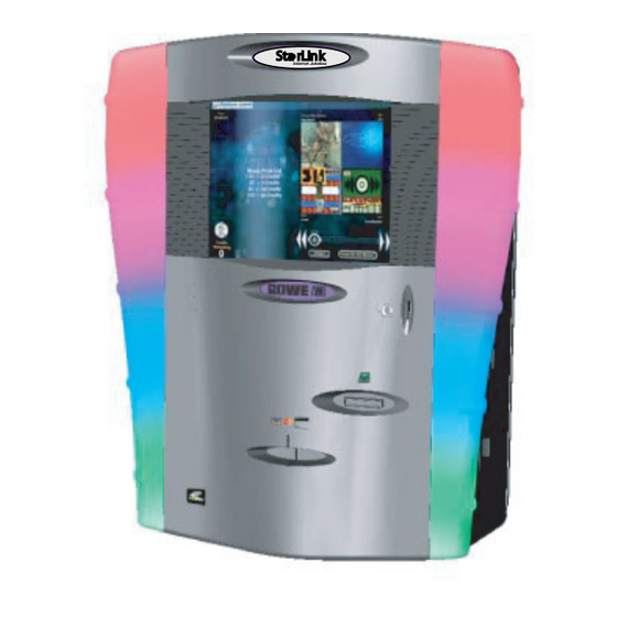
Summary of Contents for Rowe StarLink DLW-1
- Page 1 FIELD SERVICE MANUAL and PARTS CATALOG Sta rLink Sta rLink Internet Jukebox DLW-1 STUDIO SOUND 2 CHANNEL PREAMP VOLUME 1 of 1 Rev. H 21822662...
-
Page 2: Table Of Contents
TABLE OF CONTENTS SECTION 1 - UNPACKING AND SYSTEM DESCRIPTION Introduction ................................. 1-1 Features ................................1-2 General Features ............................1-2 Service Features ............................. 1-2 Unpacking Instructions ............................1-3 Exterior ................................1-3 Installation Instructions ........................... 1-3 Door ................................1-6 Visual Inspection ..............................1-6 Handy Case ................................. - Page 3 TABLE OF CONTENTS SECTION 3 - VENUE INSTALLATION (continued) Ethernet Cable Pin Out and Instructions ......................3-3 Sound System Setup ............................3-4 Extension Speaker Operation ......................... 3-4 70 Volt Speakers ............................3-4 Low Impedance Speakers ..........................3-4 4 Ohm Speakers ............................. 3-4 8 Ohm Speakers .............................
- Page 4 TABLE OF CONTENTS SECTION 5 - TROUBLESHOOTING (continued) Uninterruptable Power Supply ......................... 5-3 Green LED (on top of UPS near the UPS Power Switch) ................5-3 Building Wiring Fault LED ........................5-3 Computer Core Assembly ..........................5-3 +5 V LED ..............................5-3 TX LED ..............................
- Page 5 TABLE OF CONTENTS SECTION 7 - USING THE DLW-1 (continued) Operating the DLW-1 Jukebox - Short Sheet ....................7-4 Jukebox Music Station ............................ 7-4 To Select an Album ..........................7-4 To Select a Song ............................7-4 To Purchase an Album ..........................7-4 SECTION 8 - EXTRANET Introduction .................................
- Page 6 TABLE OF CONTENTS SECTION 9 - 2 CHANNEL SOUND SYSTEM ............... 9-1 Acoustical Compensation (Equalizer Tone Controls) ..................9-3 Equalizer Settings ............................9-3 Soft and Highly Absorbent Rooms ........................9-4 Average or Moderately Absorbent Rooms ....................... 9-5 Hard or Non-Absorbent Rooms ........................9-5 SECTION 10 - OPERATOR SCREENS ................
- Page 7 TABLE OF CONTENTS SECTION 11 - PARTS CATALOG ..................11-1 Introduction ..............................11-3 Catalog Description ..........................11-3 Parts List Description ..........................11-3 Ordering Replacement Parts ........................11-3 Main Door Assembly - External View - 17” Flat Screen .................. 11-4 Main Door Assembly - External View - 15” Flat Screen .................. 11-6 Main Door Assembly - Internal View - 15”...
-
Page 9: Important Safety Instructions
IMPORTANT SAFETY INSTRUCTIONS Read these instructions. 10) Protect the power cord from being walked on or pinched, particularly at plugs, convenience recep- Keep these instructions. tacles, and the point where they exit from the appara- tus. Heed all warnings. 11) Only use the attachments/accessories specified Follow all instructions. - Page 10 The lightning flash with arrowhead symbol, within an equilat- eral triangle is intended to alert the user to the presence of uninsulated “dangerous voltage” within the product’s enclo- sure that may be of sufficient magnitude to constitute a risk of electric shock to persons.
-
Page 11: Section 1 - Unpacking And System Description
Section 1: Unpacking & System Description Section 1: Unpacking & System Description INTRODUCTION The DLW-1 is part of a much larger system – the Ecast Interac- tive Entertainment Network. This network is a digital platform that delivers music, games, e-commerce, Internet access, films and other entertainment features to venues everywhere. -
Page 12: Features
DLW-1 Phonograph FEATURES The major DLW-1 features are: General Features: • Sturdy construction and reliable design • Conveniently located customer, operator, and service controls • All major components are modular and easy to replace, if needed • Computer controlled digital music •... -
Page 13: Unpacking Instructions
Damage claims are your responsibility. Do not return damaged merchandise until after your claim has been established. Once your claim has been established, merchandise may be returned to your Rowe distributor for repair. The invoice amount for repair charges can then be collected from the carrier. - Page 14 DLW-1 Phonograph INSTALLATION INSTRUCTIONS CAUTION Wallphono must be solidly fastened to structural members within the supporting wall. Wallphono weighs 165 pounds (75 kg); if it falls, it could cause damage or injury. CAUTION Supplied fasteners (1-1/2” lag screws) are for wood wall stud construction. For other types of construction, installer must provide and use appropriate fasteners.
- Page 15 Section 1: Unpacking & System Description 7.333 16.000 7.363 (186) (406) (187) 4.235 8.132 7.868 4.263 (108) (207) (200) (108) 17.750 (451) 33.064 (840) 66.564 (1691) .500 (13) BACK VIEW 33.500 (851) FLOOR FIGURE 1-1 21822662...
- Page 16 DLW-1 Phonograph HANG WALL PHONO ON BRACKET CAUTION Wallphono weighs 165 pounds (75 kg) and requires at least two people for lifting. To see Hanger Bracket alignment open Main Door. 1. As you lift Wallphono to Hanger Bracket, look through opened Door to be sure keyhole slots of the Wallphono Back Panel are aligned with spools of the Hanger Bracket.
- Page 17 Section 1: Unpacking & System Description MAJOR COMPONENTS OF THE DLW-1 Figure 1-3 shows the major components of the DLW-1 Phonograph. Take a minute to familiarize yourself with these components. CORE COMPUTER 22143802 The Core Computer is the heart of the system and has a removable hard drive and a single board computer. The hard drive is the only storage in the system and retains;...
- Page 18 DLW-1 Phonograph VOLUME CONTROL UNIT 34032903 (Studio Sound Model Only) This Rowelink module should be removed from bottom of phonograph and mounted remotely (behind bar, etc.). It displays and controls the volume of the amplifier channels and microphones, turns ON/OFF (power button) the phonograph lights, touchscreen monitor and Mars Bill Acceptor, rejects the selection playing, or adds a credit (same as IR remote credits).
-
Page 19: Major Components
Section 1: Unpacking & System Description Transformer Audio Output Transformer Core Computer Power Supply Assembly Rowelink Hub Assembly Extra Cool Audio Amplifier Assembly Audio/Visual Controller Assembly Volume Control Unit RESET/ATX Power Switch Touchscreen Flat Panel LCD Monitor 15"/17" Credit Card Reader Bill Acceptor and Stacker FIGURE 1-3 MAJOR COMPONENTS... -
Page 20: Touchscreen Monitor 17
DLW-1 Phonograph DLW-1 NETSTAR SPECIFICATIONS General Depth ............................26 1/2 in. Width ............................40 in. Height ............................63 in. Power Requirements ........................120 VAC 60 Hz. 1200 watts 11.9 amps Pricing ......................See Credit Pricing Screen, Section 9 Bill Acceptor ..............Mars Series 2000 w/700 Bill Stacker. Accepts $1, and $5 Coin Acceptor .................... - Page 21 Section 1: Unpacking & System Description LIGHTING Lamp Type Lamp Specs Fluorescent (2) 6 watt, 9 In. F6T5/CW Neon Custom FUSES AND CIRCUIT BREAKERS System Power Supply 120 VAC (Transformer Primary Only) ............Two 6 amp Circuit Breakers 24 VAC ...........................4 amp Fuse +12 VDC ..........................
- Page 22 DLW-1 Phonograph This page left intentionally blank 1-12 21822662...
- Page 23 3. Unlatch the two latches on the side of the Core Computer. Swing the hard drive assembly open. NOTE All hard drives will be shipped in a removable hard drive tray, designed to fit the Rowe DLW-1 CC. Check that the data and power cables are securely seated in the drive in the tray before installation.
- Page 24 DLW-1 Phonograph LINK PHONE LINE ETHERNET +5 V COM 4 MAG CARD READER CC ATX POWER SWITCH Figure 2-2 The following steps are a summary of the power-on and boot-up process. For a more detailed description please see the “Sequence of Operation” in Section 5. 1.
-
Page 25: Rowelink Controller
Section 2: Installing Hard Drive and Testing TESTING THE UNIT Once the jukebox is powered on and the user interface is running (see figure 2-5 Jukebox User Interface), try the following procedures before moving and installing the unit at the venue: PERIPHERALS Touch Screen: NOTE:... -
Page 26: Connecting Speakers
DLW-1 Phonograph CONNECTING SPEAKERS: Audio: Play a local music selection by following the procedure below. Browse through album covers on the local jukebox by pressing the arrow keys below the 4 album covers that appear on the right-hand side of the screen. To view the songs on an album, touch the album and the song list will appear to the left of the 4 album covers. -
Page 27: Section 3: Venue Installation
Section 3: Venue Installation Section 3: Venue Installation INTRODUCTION WARNING The first step of the DLW-1 installation is setting up the Network in the venue. The following procedures should only be followed once the Network is in place and has been tested by Ecast. Also, only install a jukebox that has a working and tested hard drive in the jukebox. -
Page 28: Installing The Jukebox
DLW-1 Phonograph INSTALLING THE JUKEBOX Step 1. Connect to the Network Do not connect to the network until it has been installed and tested by Ecast. The DLW-1 jukebox connects to the Internet via the router. A “straight through” Ethernet cable must be run between the jukebox and the router. -
Page 29: Section 3 - Venue Installation (Continued)
Section 3: Venue Installation ETHERNET CABLE PIN OUT AND INSTRUCTIONS Part of the jukebox installation process requires making a custom Ethernet cable, as the cable length will be unique to each venue. This cable will be run between the jukebox and router. This customization will save costly cable and result in a neater installation process. -
Page 30: Sound System Setup
DLW-1 Phonograph SOUND SYSTEM SETUP Extension Speaker Operation To avoid a poor sounding jukebox, care must be taken when adding extension speakers. Two requirements must be met: 1. Speakers must be wired so that the power consumed by the extension speakers do not exceed the amplifier power rating. -
Page 31: Selecting Speaker Power
Section 3: Venue Installation Table 3-1 Extension Speaker Worksheet Sheet 1 SELECTING SPEAKER POWER General Instructions This section will lead you through the power and speaker selection process. This process consists of four major steps and several smaller steps. The major steps are: 1. -
Page 32: Extension Speaker Worksheet
DLW-1 Phonograph Table 3-1. Extension Speaker Worksheet Sheet 2 4-OHM SPEAKERS CONNECTED TO TRANSFORMER TAPS Place the quantity of speakers in the blank under QTY and multiply the quantity times the power consumption (show stereo speakers as 2 speakers). Place your results in the blank under TOTAL. 4-Ohm Stereo Speakers connected to transformer taps Total Connections... - Page 33 Section 3: Venue Installation Table 3-1. Extension Speaker Worksheet Sheet 3 8-OHM SPEAKERS CONNECTED TO TRANSFORMER TAPS Place the quantity of speakers in the blank under QTY and multiply the quantity times the power consumption (show stereo speakers as 2 speakers). Place your results in the blank under TOTAL. 8-Ohm Stereo Speakers connected to transformer taps Total Connections...
- Page 34 DLW-1 Phonograph Table 3-1. Extension Speaker Worksheet Sheet 4 Combine consumptions of all speakers: Stereo Mono Connected to E1 - E7 ______ ______ Tapped 4-Ohm: ______ ______ Sum of tapped and A1, A2 Tapped 8-Ohm ______ ______ 70 Volt must not exceed 250 70-Volt A1, A2 ______...
- Page 35 Section 3: Venue Installation Table 3-2A. Amplifier Overload Check Check that the amplifier is not overloaded by performing the following four steps: 1. Make sure that the extension speakers are connected to the proper speaker taps. 2. Set the volume control to 63 (maximum volume) and make a selection. 3.
- Page 36 DLW-1 Phonograph AUDIO OUTPUT TRANSFORMER ASSEMBLY 32 V 24 V 16 V FROM 1000 WATT POWER AMPLIFIER FROM 1000 WATT POWER AMPLIFIER 16 V 24 V 32 V 3-10 21822662...
- Page 37 Section 3: Venue Installation THIS PAGE INTENTIONALLY LEFT BLANK 21822662 3-11...
- Page 38 DLW-1 Phonograph BR/W CHANNEL 1 OR 3 BL/W BL/W CHANNEL 2 OR 4 BR/W 40832108 TRANSFORMER WIRING DIAGRAM 3-12 21822662...
- Page 39 Section 3: Venue Installation THIS PAGE INTENTIONALLY LEFT BLANK 21822662 3-13...
-
Page 40: Speaker Synopsis
DLW-1 Phonograph SPEAKER SYNOPSIS 1000 WATTS OF RMS POWER PER AMPLIFIER OR 500 WATTS PER CHANNEL. The generic speaker wiring diagrams cover 4 to 32 speakers. Diagram 1 has a 4 speaker layout. If you only want the four speaker layout, then the maximum output of each speaker would have to be rated 4 ohms and capable of 300 watts. - Page 41 Section 3: Venue Installation 21822662 3-15...
- Page 42 DLW-1 Phonograph 3-16 21822662...
- Page 43 Section 3: Venue Installation 21822662 3-17...
- Page 44 DLW-1 Phonograph 3-18 21822662...
- Page 45 Section 3: Venue Installation 21822662 3-19...
- Page 46 DLW-1 Phonograph 3-20 21822662...
-
Page 47: Section 4: Routine Service
Section 4: Routine Service Section 4: Routine Service INTRODUCTION Routine and preventative maintenance is to be performed on your normal periodic service call. This section discusses how to collect money, perform the cash audit, and do preventive mainte- nance procedures. Changing music, collecting statistic figures, and changing other venue specific features can be done via the Extranet at the Operator’s office or at the venue. -
Page 48: Collecting Money
DLW-1 Phonograph COLLECTING MONEY The following describes how to remove cash from the jukebox and record the non-resetting cash value. Step 1: Turn the jukebox lock and allow the jukebox to open. Step 2: Remove the cashbox and empty out all coins, then remove all bills from stacker. Step 3: Push COLLECT switch on Rowelink Controller. -
Page 49: Preventive Maintenance
Section 4: Routine Service PREVENTIVE MAINTENANCE Preventive maintenance should be performed at regular intervals. At every visit, the exterior should be cleaned and the touch screen should be re-calibrated. Every 3-4 months, the interior should be cleaned. EXTERIOR Part Procedure Touch Screen Clean with household glass cleaner and paper towel or clean cloth. - Page 50 DLW-1 Phonograph This page intentionally left blank 21822662...
-
Page 51: Section 5: Troubleshooting
• A sequence of operation explanation, a Block Diagram (figure 5-1), and wiring diagram (figure 5-2) to help you isolate the problem to a harness or a module. The figures also show the Rowe part numbers of the harnesses and modules. -
Page 52: Dlw-1 Led's
DLW-1 Phonograph DLW-1 LED’S POWER SUPPLY BOARD +9 V LED Should be on. On when +9 VDC is available at the Power Supply. +12 V LED Should be on. On when +12 VDC is available at the Power Supply. +24 V LED Should be on. -
Page 53: Volume Control
Section 5: Troubleshooting VOLUME CONTROL (STUDIO SOUND ONLY) PERIOD LED (on the 10’s digit) Should be dimly flashing ** at a relatively fast rate. Flashes when Rowelink Master Commands are sent from the Computer Core via the ROWELINK CONTROLLER. PERIOD LED (on the 1’s digit) Should be dimly flashing ** at a relatively fast rate. -
Page 54: Sequence Of Operation
DLW-1 Phonograph SEQUENCE OF OPERATION Step 1: Power on the jukebox • With the System Power Supply power switch in the ON position, plug the AC power from the back of the jukebox into a standard, grounded wall outlet. The fluorescent and neon lamps will light, and the Volume Control Unit (Studio Sound Only) display will show dashes. - Page 55 Section 5: Troubleshooting Step 6: Selection is played • Computer sends a Rowelink message to the Audio/Video Controller (for Studio Sound) or the Rowelink Controller (for 2 Channel Preamp)to un-mute the amplifier. • Song is located on the local computer hard drive, and played. Use Volume Control Unit to adjust volume. 21822662...
- Page 56 DLW-1 Phonograph MDB BILL ACCEPTOR ROWELINK Relay Switched 120 VAC CREDIT PULSE Power Mars Series and ENABLE PULSE BILL 2000 Bill ACCEPTOR ROWELINK Acceptor IMONEX 2 Channel CREDIT PULSE COIN SWITCHES COIN ACCEPTOR (OPTIONAL) MARS 330/212 CREDIT PULSE NRI G-13 ELECTRONIC and +12 V COIN CONTROLS C120...
- Page 57 Section 5: Troubleshooting ETHERNET ROWELINK Router COM 2 ROWELINK (Located outside of Phonograph) Link Audio Left and Right Relay 22151901 switched MONITOR 17 inch SVGA 120 VAC Stereo COM 1 POWER ROWELINK TFT-LCD power SUPPLY Touchscreen Power SVGA Monitor VIDEO Relay Status 22143802...
- Page 58 DLW-1 Phonograph 34032901 Volume Control Unit ON/OFF CTRL Channel or Microphone MUTE NOT ROWELINK B ROWELINK A +9 VDC +9 V COMMON 34037908 RJ12 MIC1 MIC2 MIC3 MIC4 Volume 22135602 DOWN On-Microphone Off-Channel 120 VAC 34022310 CREDIT POWER REJECT MODE GROUND +5 VDC CREDIT/INTERRUPT...
- Page 59 Section 5: Troubleshooting MOUSE 22143802 MINI-DIN 6 CORE COMPUTER MAG CARD READER 34038902 34039201 PS2 KEYBOARD RXDd < PANASONIC TXDd > ZU-1890M103 +5 VDC +5 VDC MAGNETIC CARD READER .50 CONNECTOR MINI-DIN 6 ASSY RJ12 EHTERNET PHONE LINE COM4 EHTERNET RJ12 LEDS RJ45 JACK...
- Page 60 DLW-1 Phonograph TO COMPUTER CORE AUDIO LEFT AND RIGHT TO ROWELINK CONTROLLER RJ12 RJ12 ON/OFF CTRL MUTE NOT CONNNECTOR 40917401 ROWELINK B LEFT RIGHT ROWELINK A ROWELINK +9 VDC EXTREMELY +9 V COMMON STEREO MECHANISM COOL 22136410 AUDIO/VIDIO NON-INVERT CONTROLLER POWER RESET RESET...
- Page 61 Section 5: Troubleshooting UPPER LAMP LAMP BRACKET 120 V DOOR HARNESS GROUND 40898710 LOWER LAMP LAMP BRACKET GROUND 1 2 3 4 5 6 7 8 9 1 2 3 4 5 6 7 8 9 NEON LAMPS 5000 VAC 20 mA BALLAST SHIELDED NEON...
-
Page 62: Dlw-1 Block Diagram - 2 Channel Preamp
DLW-1 Phonograph Relay MDB Bill Switched Acceptor Rowelink Credit Pulse 120 VAC Mars Series (RS232) and Enable Power 2000 Bill Pulse Bill Acceptor Acceptor Credit Pulse Imonex 2 Channel Coin Switches Coin Acceptor (Optional) Credit Pulse Mars 330/212 Electronic and +12 V Nri G-13 Coin Coin Controls C120... - Page 63 Section 5: Troubleshooting Ethernet ROUTER Rowelink COM 2 (Located outside of Phonograph) Link Rowelink Relay Audio Left Switched 22160801 or 22151901 Monitor and Right 120 VAC 15 or 17 inch Power COM 1 Power SVGA TFT-LCD Supply Stereo Input Touchscreen Monitor SVGA Relay 22143802...
-
Page 64: Dlw-1 Wiring Diagram - 2 Channel Preamp
DLW-1 Phonograph 22135602 120 VAC 34022310 34037910 GROUND +5 VDC CREDIT/INTERRUPT ESCROW/SEND /ENABLE Mars AC2411-U7E Bill Acceptor TO POWER SUPPLY 1 2 3 4 5 6 7 8 910 1 2 3 4 5 6 1 2 3 DUAL ROW COUNTER BILL ACCEPTOR MDB ACCEPTOR... - Page 65 Section 5: Troubleshooting TO COMPUTER CORE AUDIO LEFT AND RIGHT TO CONTROL 22145604 PANEL VOLUME CONTROL LEFT RIGHT VOLUME 61138701 CONTROL TO ROWELINK 2 CHANNEL STEREO MECHANISM CONTROLLER PREAMP P3 AMP MUTE 21620706 POWER CONNNECTOR JUMPER MUTE RESET BL/W 1 2 3 O/B-1 34032605 OUTPUT...
- Page 66 DLW-1 Phonograph MOUSE 22143802 MINI-DIN 6 CORE COMPUTER MAG CARD READER 34038902 34039201 PS2 KEYBOARD RXDd < PANASONIC TXDd > ZU-1890M103 +5 VDC +5 VDC MAGNETIC CARD READER .50 CONNECTOR MINI-DIN 6 ASSY RJ12 EHTERNET PHONE LINE COM4 EHTERNET RJ12 LEDS RJ45 JACK TOUCHSCREEN...
- Page 67 Section 5: Troubleshooting UPPER LAMP LAMP BRACKET 120 V DOOR HARNESS GROUND 40898710 LOWER LAMP LAMP BRACKET GROUND 1 2 3 4 5 6 7 8 9 1 2 3 4 5 6 7 8 9 NEON LAMPS 5000 VAC 20 mA BALLAST SHIELDED NEON...
-
Page 68: Troubleshooting Charts
DLW-1 Phonograph TROUBLESHOOTING CHARTS The best way to isolate a problem is to determine its cause. The following charts should help to narrow down which module is failing and whether it can be fixed or needs to be replaced. Start with finding the “Trouble” column that relates the closest to the problem you are experiencing and then match it to the closest “Symptom”. - Page 69 Section 5: Troubleshooting Trouble Symptom Probable Cause Jukebox will not operate When plugged into a standard 1. The Power button was pressed on when powered ON wall outlet the florescent lights Volume Control Unit or IR Remote. fail to light 2.
- Page 70 DLW-1 Phonograph Trouble Symptom Probable Cause The bill acceptor does not The bill acceptor will not 1. The cash box is full work accept a bill 2. The cash box was not re-installed on bill acceptor correctly 3. There is a jammed bill in the device 4.
- Page 71 Section 5: Troubleshooting Trouble Symptom Probable Cause 3. The line was not installed in the pre-selected location 4. The line (jack) was not labeled by the technician Router does not work When the power button is 1. The AC power plug is not fully depressed nothing happens inserted in the receptacle on the back of the router...
- Page 72 DLW-1 Phonograph This page intentionally left blank 5-22 21822662...
-
Page 73: Section 6: Network
Section 6: Network Section 6: Network INTRODUCTION In order to bring the DLW-1 Network and the Internet to each venue, a separate phone line must be installed at each site. Depending on availability and the geographic location of the venue, the line will be a standard phone line providing dial-up Internet service, or digital cable, wireless broadband, or symmet- ric Digital Subscriber Line (DSL) providing faster Internet ser- vice. -
Page 74: Where To Install The Designated Line And Router
DLW-1 Phonograph WHERE TO INSTALL THE DESIGNATED LINE AND ROUTER First and foremost, Ecast wants to make the installation process for the Operator as easy and smooth as possible. We realize that the DLW-1 System requires another piece of equipment, the router, and more wired connections than previous Jukeboxes, but it doesn’t have to be more work than need be. -
Page 75: Installing The Designated Line
Section 6: Network INSTALLING THE DESIGNATED LINE DSL: If the venue is in an area where DSL is available, Ecast will order the installation of this technology. The time line for getting DSL installed in a venue is slightly longer than dial-up, but the technology is preferable as it provides a faster Internet connection. -
Page 76: Installing The Router
DLW-1 Phonograph INSTALLING THE ROUTER Introduction The DLW-1 Router provides two major functions for the DLW-1 System. It is the connecting hub for theDLW-1 Jukebox in the venue and delivers the Internet from the outside world. The router box is the smart-translation tool that dials into the designated phone line and delivers the Internet to the Units in the bar (see Figure 6-1). - Page 77 Section 6: Network The following steps describe how to install the router in the venue: Step 1: Select a Location Regardless of where the designated telephone jack was installed, the router box must be kept away from tampering, accidental shut off or from tech-savvy customers who could potentially steal Internet service from the venue (and operator).
-
Page 78: Standard Phone Cable Pin Out And Sources
DLW-1 Phonograph STANDARD PHONE CABLE PIN OUT & SOURCES A longer phone cable will be needed if the Router is placed at a greater distance than the provided cable. This cable has 2 twisted pairs with pin 1 to pin 4, pin 2 to pin 3, pin 3 to pin 2, and pin 4 to pin 1. It is available in different lengths, or parts to make your own custom length can be purchased at Radio Shack, Digi-Key, or other sources. -
Page 79: Section 7: Using The Dlw-1
Section 7: Using the DLW-1 Section 7: Using the DLW-1 INTRODUCTION The following is a reference guide for the Operator to navigate the user interface on the DLW-1 Jukebox. There are a couple reasons why it is important that the Operator feels comfortable with all of the user interface features. -
Page 80: Operating The Dlw-1 Jukebox
DLW-1 Phonograph OPERATING THE DLW-1 JUKEBOX Use this reference guide to navigate the DLW-1 Jukebox APPROACHING THE JUKEBOX Attract loop: This moving image file consists of advertisements and graphics and appears when no one has touched the system for a few minutes. Simply touch the screen to begin using the system. The attract loop will automatically disappear. Getting started: Touch any part of the screen to begin viewing album covers. -
Page 81: Using The System
Section 7: Using the DLW-1 USING THE SYSTEM Selecting Local Music: Browse through album covers on the local jukebox by pressing the arrow keys below the 4 album covers that appear on the right hand side of the screen. To view the songs on an album, touch the album and the song list will appear to the left of the 4 album covers. -
Page 82: Jukebox Music Station
DLW-1 Phonograph OPERATING THE JUKEBOX – SHORT SHEET Jukebox Music Station To select an Album — Two Ways: 1. Scroll through the groupings of 4 album covers using the scroll bar at the bottom of the screen. Touch the album and the song list will appear on the screen. 2. -
Page 83: Section 8: Extranet
Section 8: Extranet Section 8: Extranet INTRODUCTION The Extranet is an Internet that only a company’s employees and their business partners can access. This private Internet is ac- cessed by a given username and password. Only information that pertains to the user logged in can be viewed and accessed by that user. -
Page 84: General Questions For Internet Beginners
DLW-1 Phonograph GENERAL QUESTIONS FOR INTERNET BEGINNERS Clicking: To click, press and immediately release the left button on your mouse. Pull-down menus: Pull-down menus give you access to a list without taking up a lot of space. A pull-down menu is a horizontal, rectangular box with an arrow on the right pointing down. -
Page 85: General Questions For Everyone
Section 8: Extranet GENERAL QUESTIONS FOR EVERYONE How do I access the Extranet? Bring up any internet browser, for example: Netscape, Internet Explorer, or AOL. Type in the following address: www.ecastcentral.com My username and password: Your username identifies you to the DLW-1 Management System. Your password tells the system that the person logging in with your username is really you. -
Page 86: Revenue Reports
DLW-1 Phonograph REVENUE REPORTS By clicking on a venue name you can view details of the revenue generated and select options to generate reports for specific time periods. USAGE REPORTS By clicking on a venue name you can view top songs, albums, and games. Options include list length (top 10 or top 40) and time period. -
Page 87: Update Music
Section 8: Extranet UPDATE MUSIC Adding, deleting albums Use either the Auto Suggest, Music Advisor, or Manual Select/Manual Remove features described below. Auto Suggest In this section, Ecast recommends what albums to download to or remove from a particular location’s DLW-1 System based on the location’s profile;... -
Page 88: Manual Select/Remove
DLW-1 Phonograph Manual Select/Remove This section enables you to search for a specific album, artist, song, or genre, and then choose from the resulting list what albums you want to add or delete. To add music, click one of the venues listed on the Update Music home page, then click the “Manual Select” button in the “Add Music”... -
Page 89: Edit Profile
Section 8: Extranet EDIT PROFILE What Can I edit? You can change any profile within editable text area. To change, just highlight the old information by clicking on it, then type in the new data. If you want to edit the sections you can’t change yourself, email Ecast customerservice@ecastinc.com or call toll free (877) 451-1537 with your edit requests. - Page 90 DLW-1 Phonograph This page intentionally left blank 21822662...
-
Page 91: Section 9: 2 Channel Sound System
Section 9: 2 Channel Sound System Section 9: 2 Channel Sound System INTRODUCTION This section shows the single and dual volume control connec- tions and equalizer tone controls for highly, moderate, and non- absorbent rooms. - Page 92 DLW-1 Phonograph ORDER ROWE CABLE 20819908 Dual Remote Volume and Cancel Control 30632209 ORDER ROWE CABLE 20819907 Remote Volume and Cancel Control 30632201...
-
Page 93: Sound System
Section 9: 2 Channel Sound System SOUND SYSTEM Acoustical Compensation (Equalizer Tone Controls) The preamplifier contains seven tone controls on each channel to compensate for room acoustics in various locations. These controls are on the amplifier chassis. The sound level at which the phonograph will be operated and the room furnishings determine the settings of these controls. -
Page 94: Soft And Highly Absorbent Rooms
DLW-1 Phonograph If the Room or Speaker System Requires a Trade-Off The equalizer limits the volume of all of the audio frequencies. Therefore, to achieve the best sound for a specific room or set of speakers, you may find that most of the graphic equalizer controls need to be turned down. In this situation, the overall phonograph volume may not be adequate. -
Page 95: Average Or Moderately Absorbent Rooms
Section 9: 2 Channel Sound System Average or Moderately Absorbent Rooms These are the factory settings. 1. Turn all seven right channel and seven left channel graphic equalizer controls fully counterclockwise. 2. The graphic equalizer's controls should now be set as LEFT CHANNEL RIGHT CHANNEL MONO... - Page 96 DLW-1 Phonograph This Page Intentionally Left Blank...
-
Page 97: Section 10: Operator Screens
Section 10: Operator Screens Section 10: Operator Screens The service mode consists of 36 operator screens. Pressing the SERVICE switch on the switches circuit board enters the service mode and displays the first screen, the MAIN MENU operator screen. Touch the screen to navigate between screens, choose programming options, and enter data. -
Page 98: Service Mode Map
DLW-1 Phonograph SERVICE MODE MAP Main Menu System Auditing Collection - Touch button to display Collection screen. Pricing and Play Options Song Play Order • FIFO “First In First Out (Default). Songs play in order selected • Random. Songs play in random order. Credit Pricing •... - Page 99 Section 10: Operator Screens System Settings - View system settings Network Settings - view network settings System Diagnostics • Quick Diagnostic • Network Diagnostic • Application logs Update Controller - Touching the Force Update button initiates a full system update. Configuration Summary View summary of Last Collection, Credit Pricing, Play Song Order, Auto Play, Queue Recovery, and Credit Recovery.
-
Page 100: Main Menu
DLW-1 Phonograph MAIN MENU The service button inside the Netstar box will lead you to our Operator Screens. The MAIN MENU SCREEN is the main operator screen. All setup programming can be reached from here. Touch “quit” to exit the service mode and return to the MUSIC SELECTION SCREEN. -
Page 101: Collection
Section 10: Operator Screens COLLECTION This screen displays the current and previous col- lection and play totals. After collecting the money, touch “Collect NOW” to add current period totals to ALL periods, transfer totals from the Current Period into the Last Period, and clear the Current Period. The All Periods totals show lifetime unit totals. -
Page 102: Song Play Order
DLW-1 Phonograph SONG PLAY ORDER Sets the music play for FIFO “First-in First-out” or Random. The button will turn orange when touched to indicate an active choice. Touch "back" to return to the previous screen. PRICING OPTIONS Sets up pricing for selections. The button will turn orange when touched to indicate an active choice. -
Page 103: Add Free Credits
Section 10: Operator Screens ADD FREE CREDITS Adds a credit each time “Add Credit” is touched. Touch "back" to return to the previous screen. AUTOPLAY MODE Touch a button to set Autoplay OFF or ON. The button will turn orange when touched to indicate an active choice. -
Page 104: Clear Credit/Clear Queue
DLW-1 Phonograph CLEAR CREDITS/CLEAR QUEUE Touch an orange button to clear all credits or the song queue. Touch "back" to return to the previous screen. RECOVER CREDITS/RECOVER QUEUE This screen is used to access the recover screens. Touch "back" to return to the previous screen. 10-8 21822662... -
Page 105: Recover Queue
Section 10: Operator Screens RECOVER QUEUE Touch a button to select Queue Recovery OFF or ON. The button will turn orange when touched to indicate an active choice. To change the number of minutes, touch “Change Interval”. Use the keypad to enter the new value, then touch CHANGE. -
Page 106: Recover Credits
DLW-1 Phonograph RECOVER CREDITS Touch a button to select Credit Recovery OFF or ON. The button will turn orange when touched to indicate an active choice. To change the number of minutes, touch “Change Interval”. Use the keypad to enter the new value, then touch CHANGE. -
Page 107: Hardware/Diagnostics
Section 10: Operator Screens HARDWARE/DIAGNOSTICS This screen is used to access the hardware and diagnostic screens. Touch "back" to return to the previous screen. CALIBRATE TOUCHSCREEN When this screen appears, close the phonograph top door and follow directions on the screen to calibrate the touchscreen. -
Page 108: Rowelink Configuration
DLW-1 Phonograph FOR 2 CHANNEL PREAMP ONLY FOR STUDIO SOUND ONLY ROWELINK CONFIGURATION This screen is used to access other screens. “Back to Peripheral Setup” will return you to the Hardware/Diagnostics screen. “Quit” will end the Service Mode and return to the Music Selection screen. BACK BACK UNDO... -
Page 109: Pricing Setup
Section 10: Operator Screens BACK SAVE UNDO PRICING SETUP Settings match the configuration of the electronic coin mech and the Mars bill acceptor (25 = Quarter, 100 = Dollar, etc.). The settings are: Coin Bill 1 = 0 1 = 100 2 = 25 2 = 200 3 = 100... -
Page 110: Audio Volume Presets
The Audio Volume Presets outputs are adjustable to match the output level of the Audio/Video Controller to the specified input level of different Power Amplifiers. The 60% factory setting is for the Rowe 1000 watt Extremely Cool Audio Digital Power Amplifier. If it is set too high, the sound will be distorted at maximum volume or the music may disappear from one or both channels. -
Page 111: Audio Modes - Input Select
Section 10: Operator Screens BACK SAVE UNDO AUDIO MODES - INPUT SELECT This is the first of three screens. Each screen has four modes: Audio, Standby, Background, and Mi- crophone. Touch “Muting” or “Output Mode” to access the other two screens. For each mode the Audio/Video Controller can select its front-end input signal from the Sound Card, Stereo A, Stereo B, or Mono RCA jacks. -
Page 112: Audio Modes - Output Mode
DLW-1 Phonograph BACK SAVE UNDO AUDIO MODES - OUTPUT MODE The Core Computer sound card outputs a stereo signal that connects to the STEREO MECHA- NISM INPUT RCA jacks on the Audio/Video Controller. The Audio/Video Controller has cir- cuitry that combines the stereo signal to produce a mono signal. -
Page 113: Remote Control Setup - Parameters
Section 10: Operator Screens BACK SAVE UNDO BACK SAVE UNDO FOR 2 CHANNEL PREAMP ONLY FOR STUDIO SOUND ONLY REMOTE CONTROL SETUP - PARAMETERS This is the first of three screens. Touch “IR Settings” or “VCU Settings” to access those screens. Remote Credit enables/disables credits being given by the IR remote and the VCU (volume control unit). -
Page 114: Remote Control Setup - Ir Settings
DLW-1 Phonograph SAVE BACK UNDO BACK SAVE UNDO FOR STUDIO SOUND ONLY FOR 2 CHANNEL PREAMP ONLY REMOTE CONTROL SETUP - IR SETTINGS IR SETTINGS: Enables or disables Autoplay Override, Pause, Reject, and Input Select on the IR. Factory settings disable all except Reject. -
Page 115: Remote Control Setup - Vcu Settings
Section 10: Operator Screens SAVE BACK UNDO REMOTE CONTROL SETUP - VCU SETTINGS This screen enables and disables individual switches on VCU’s (Volume Control Unit’s). Up to 4 VCU’s can be connected to the phonograph. This allows different rooms to have their own volume control unit. -
Page 116: Microphone Setup - Setup
DLW-1 Phonograph SAVE BACK UNDO MICROPHONE SETUP - SETUP This is the first of two microphone screens. Touch “Routing” to access the other screen. The microphones TYPE are factory set to “Paging” indicated by the red buttons and should not be changed to NA. -
Page 117: System Settings
Section 10: Operator Screens SYSTEM SETTINGS A read-only screen showing the system settings and status. NETWORK SETTINGS A read-only screen the showing network settings and status. SYSTEM DIAGNOSTICS This screen is used to access the diagnostic screens. Touch "back" to return to the previous screen. 21822662 10-21... -
Page 118: Quick Diagnostics
DLW-1 Phonograph QUICK DIAGNOSTICS A read-only screen used for diagnostics. NETWORK DIAGNOSTICS A read-only screen used for diagnostics. APPLICATION LOGS A read-only screen used for diagnostics. Touch "back" to return to the previous screen. 10-22 21822662... -
Page 119: Update Controller
Section 10: Operator Screens UPDATE CONTROLLER CAUTION: Do not use the “Force Update” feature without prior approval from Customer Service. CONFIGURATION SUMMARY A read-only screen. MUSIC FILTER Categories with a check mark will not be played on this machine. Place or remove a check mark by touching the white box. -
Page 120: Spanish User Interface
DLW-1 Phonograph SPANISH USER INTERFACE 10-24 21822662... -
Page 121: Adding A Bgm (Background Music) Unit
Section 10: Operator Screens ADDING A BGM (BACKGROUND MUSIC) UNIT STUDIO SOUND ONLY Do not skip steps. All steps must be done to navigate properly through the menus. If you get lost, back through the menus by touching: back, the back arrow, or Back to Peripheral Setup. Step 1. -
Page 122: Adding Microphones
BACK, the BACK arrow, or Back to Peripheral Setup. Up to three microphones can be plugged into the Audio/Video Controller and used for paging. Microphones can be Rowe, low- level balanced, or low-level unbalanced. All microphones must have a momentary PUSH to TALK switch (see Figure xxx). - Page 123 Section 10: Operator Screens Step 6. When a microphone is keyed, the Audio/Video Controller can select its front-end input signal from the Sound Card, Stereo A, Stereo B, Mono, or Unchanged. The factory setting of Unchanged does not switch front- end inputs when a microphone is keyed.
- Page 124 DLW-1 Phonograph STUDIO SOUND ONLY 10-28 21822662...
-
Page 125: Separate Volume Control Of Speaker Zones
Section 10: Operator Screens SEPARATE VOLUME CONTROL of SPEAKER ZONES STUDIO SOUND ONLY Do not skip steps. All steps must be done to navigate properly through the menus. If you get lost, back through the menus by touching: back, the back arrow, or Back to Peripheral Setup. TWO MONO ZONES or FOUR MONO ZONES The Main/Phono Amplifier gets its input from Audio/Video Controller outputs Ch1 and Ch2 and supplies two mono zones. - Page 126 DLW-1 Phonograph ONE STEREO ZONE and TWO MONO ZONES This requires a second amplifier. The Main/Phono Amplifier gets its input from Audio/Video Controller outputs Ch1 and Ch2 and supplies a stereo zone. The second amplifier gets its input from Audio/Video Controller outputs Ch3 and Ch4 and supplies two mono zones.
-
Page 127: Keypad
Section 10: Operator Screens KEYPAD Operator Screen Programming may require numbers to be input on the various screens. When this is the case, a pop-up keypad will appear on the screen with a value in it from the space you touched. Touch C to clear the value, enter the value desired, and press OK. - Page 128 DLW-1 Phonograph This page left intentionally blank 10-32 21822662...
-
Page 129: Section 11: Parts Catalog
Section 11: Parts Catalog INTRODUCTION ............................11-3 Catalog Description ......................... 11-3 Parts List Description ........................11-3 Ordering Replacement Parts ......................11-3 MAIN DOOR ASSEMBLY (EXTERNAL VIEW) 17" FLAT SCREEN ............11-4 MAIN DOOR ASSEMBLY (EXTERNAL VIEW) 15" FLAT SCREEN ............11-6 MAIN DOOR ASSEMBLY (INTERNAL VIEW) 15"... - Page 130 This page intentionally left blank. 11-2 21822662...
-
Page 131: Catalog Description
Index numbers are not used when items are listed for reference purposes only or when the item listed is an alternate part. · Rowe Part Number — This column lists the part number to use when ordering replacement parts or making inquiries. ·... - Page 132 Figure 11-1. Main Door Assembly (External View) 7" FLAT SCREEN Starlink Starlink Internet Jukebox 11-4 21822662...
-
Page 133: Main Door Assembly (External View) 17" Flat Screen
Figure 11-1. Main Door Assembly (External View) 17" FLAT SCREEN Ref. Part No. Description 22152001 Main Door Assembly (Silver)................Ref. 22152002 Main Door Assembly (Black) ................Ref. 22148001 Center Door Panel (Silver/Grey) ................1 22148002 Center Door Panel (Black/Grey) ................1 22149202/03 Lower Logo Glass (02 Lavender background, 03 Red/Orange background) ... 1 22148102/01 Lens - Wing (Left) (01 Translucent White, 02 Translucent) ......... - Page 134 Figure 11-1A. Main Door Assembly (External View) 15" FLAT SCREEN Starlink Starlink Internet Jukebox 11-6 21822662...
- Page 135 Figure 11-1A. Main Door Assembly (External View) 15" FLAT SCREEN Ref. Part No. Description 22152003 Main Door Assembly (Silver)................Ref. 22152004 Main Door Assembly (Black) ................Ref. 22148001 Center Door Panel (Silver/Grey) ................1 22148002 Center Door Panel (Black/Grey) ................1 22149202/03 Lower Logo Glass (02 Lavender background, 03 Red/Orange background) ... 1 22148102/01 Lens - Wing (Left) (01 Translucent White, 02 Translucent) .........
- Page 136 Figure 11-2. Main Door Assembly (Internal View) 15" Flat Screen 17, 18, 19 15, 16 17" Flat Screen 11-8 21822662...
- Page 137 Figure 11-2. Main Door Assembly (Internal View) Ref. Part No. Description 22152001 Main Door Assembly (Silver/Grey) ..............Ref. 22152002 Main Door Assembly (Black/Grey) ..............Ref. 22149701 Security Bracket - Top ..................1 80443004 #8-32 x 1/4 Hex WRHMS ..................4 22151901 17"...
- Page 138 Figure 11-2. Main Door Assembly (Internal View) Continued from Page 10-9 Ref. Part No. Description 22153901 Bracket Assembly - Flatscreen Transformer ............1 80443006 #8-32 x 3/8 Hex WRHMS (SF) ................1 22148901 Hinge - Door ......................1 80443006 #8-32 x 3/8 Hex WRHMS ..................9 34041501 Bracket - Chute Mounting (Door) ................
- Page 139 This page intentionally left blank 11-11 21822662...
-
Page 140: Shell Assembly (Internal View) 1000 Watt Studio Sound
Figure 11-3. Shell Assembly (Internal View) 1000 Watt Studio Sound 11-12 21822662... - Page 141 Figure 11-3A. Shell Assembly (Internal View) 1000 Watt 2 Channel Preamp 11-13 21822662...
- Page 142 Figure 11-3B. Shell Assembly (Internal View) 1000 Watt Studio Sound and 1000 Watt 2 Channel Preamp Components in this view are common to the Studio Sound and 2 Channel Preamp 11-14 21822662...
- Page 143 Figure 11-3, 11-3A, and 11-3B. Shell Assembly (Internal View) 1000 Watt Studio Sound and 1000 Watt 2 Channel Preamp Ref. Part No. Description Shell Assembly Internal View .................... Ref. 22147401 Shell Assembly ........................1 22143802 Core Computer Assembly (See Figure 11-4) ................. 1 22146601 Computer Mounting Bracket (Left) ..................
- Page 144 Figure 11-3, 11-3A and 11-3B. Shell Assembly (Internal View) 1000 Watt Studio Sound and 1000 Watt 2 Channel Preamp Continued from Page 11-15 Ref. Part No. Description 21946301 Plate - Lockbar ...................... 1 22145801 Power Supply Assembly (See Figure 11-9) ............1 40737803 Power Transformer ....................
- Page 145 This page intentionally left blank 11-17 21822662...
- Page 146 Figure 11-4. Core Computer Assembly 11-18 21822662...
-
Page 147: Core Computer Assembly
Figure 11-4. Core Computer Assembly Ref. Part No. Description 22143802 Core Computer Assembly ................Ref. 22143901 Chassis - Core Computer ..................1 80443006 #8-32 x 3/8 Hex Wrhs (SF) ................. 28 80351608 #4-40 x 1/2 Rdhms ....................7 22144301 Bracket - Computer Card Mounting ..............1 22142202 Label - Wiring (RES/ATX PWR/USB) .............. - Page 148 Figure 11-5. I/O Sub-assembly - Left (Computer) Ref. Part No. Description 22145301 I/O Sub-assembly - Left (Computer) ..............Ref. 22144901 Bracket - Left I/O Board Mounting ................. 1 61137001 CBA - 10 Interface (Slot 2) ..................1 80443006 #8-32 x 3/8 Hex WRHMS (SF) ................2 11-20 21822662...
- Page 149 Figure 11-6. I/O Sub-assembly - Right (Computer) Ref. Part No. Description 22145401 I/O Sub-assembly - Right (Computer) ............. Ref. 22145001 Bracket - Right I/O Board Mounting ..............1 61137001 CBA - 10 Interface (Slot 1) ..................1 80443006 #8-32 x 3/8 Hex WRHMS (SF) ................3 11-21 21822662...
- Page 150 Figure 11-7. Intermediate Board Sub-assembly Ref. Part No. Description 22150601 Intermediate Board Sub-assembly ..............Ref. 22145101 Bracket - Board Mounting (Computer) ..............1 70500209 Spacer - Self-Retaining (#8 Nylon) ............... 4 34040201 CBA - Interconnect (Hard Dr/CC) ................. 1 80443008 #8-32 x 1/2 Hex WRHMS (SF) ................
-
Page 151: Computer Drive Door Assembly
Figure 11-8. Computer Drive Door Assembly Ref. Part No. Description 22144101 Computer Drive Door Assembly ..............Ref. 22144801 Bracket - Drive Bay Mounting ................2 xxxxxxx #6-32 Screw (Supplied With Hard Drive Bay) ............. 4 22144701 Hinge - Door ......................1 80443004 #8-32 x 1/4 Hex WRHMS (SF) ................ -
Page 152: Power Supply Assembly
Figure 11-9. Power Supply Assembly Ref. Part No. Description 22145801 Power Supply Assembly ..................Ref. 22145901 Chassis - Power Supply ..................1 80443006 #8-32 x 3/8 Hex WRHMS (SF) ................12 30785702 Switch - Rocker (DPST) ..................1 80713010 #8-32 x 5/8 Hex WRHMS (SEMS) ................. 2 22118701 Power Inlet IEC 320 C-14 .................. -
Page 153: A/V Controller - 4 Channel
Figure 11-10. A/V Controller - 4 Channel Ref. Part No. Description For 1000 Watt Studio Sound Only 40917401 A/V Controller - 4 Channel .................. Ref. 40920701 Base Assembly - Preamp ..................1 61128802 CBA - A/V Controller (4 Channel) ................1 70500209 Spacer - Self-Retaining .................. -
Page 154: Channel Preamp
Figure 11-11. 2 CHANNEL PREAMP Ref. Part No. Description FOR 1000 WATT 2 CHANNEL ONLY 61138701 2 Channel Preamp Assembly ..................Ref. 61138601 Preamp Cover ........................1 40928701 Preamp Base ........................1 NOT SHOWN: 21620706 Jumper Plug Assembly ......................1 11-26 21822662... -
Page 155: Output Transformer Assembly
Figure 11-12. Output Transformer Assembly Ref. Part No. Description 40832108 Output Transformer Assembly ..................Ref. 61133101 Chassis - Audio Output ......................1 40633503 Transformer - Output ......................2 30426701 Binding Post Strip ......................... 2 30426706 Binding Post Strip ......................... 1 80442306 #6-32 x 3/8 Thread Form ...................... -
Page 156: Rowelink Controller Assembly
Figure 11-13. Rowelink Controller Assembly Ref. Part No. Description 40926001 Rowelink Controller Assembly ................Ref. 40925801 Base - Rowelink Controller ..................1 61135701 CBA - Rowelink Controller ..................1 80713008 #8-32 x 5/16 Hex WRHMS (SEMS) ................ 8 80443008 #8-32 x 1/2 Hex WRHMS (SF) ................4 40925901 Cover - Rowelink Controller .................. -
Page 157: Hanger Bracket Assembly
Figure 11-14. Hanger Bracket Assembly Ref. Part No. Description 61114002 Hanger Bracket Assembly .................. Ref. 87843700 #10-32 Hex Keps Nut ..................... 4 34015401 Standoff - Hanger ....................4 61114102 Hanger - Weld Assembly ..................1 89973724 #10-32 x 1 1/2 Carriage Bolt ................... 4 11-29 21822662... - Page 158 ACCESSORY EQUIPMENT FOR 2 CHANNEL PREAMP ONLY Part No. Description Function 26704402 Phonograph paging system with Paging system not affected by A.V.C. All plug-in unit, hand held microphone complete with microphone and 50 foot microphone cable. 26694703 Amplifier Accessory Kit Provides assess to auxiliary inputs and outputs of the NOTE: This kit will work with all preamplifier.
Need help?
Do you have a question about the StarLink DLW-1 and is the answer not in the manual?
Questions and answers